
jawilson20
Well-Known Member
I have been brewing for about a year now and shortly after getting my first Cooper's Kit I stumbled upon Homebrewtalk and the inspiring DIY forum. So needless to say it wasn't long until I had set my eyes on Lonnie Mac's original Brutus 10 and said "I am gonna build that" without having the slightest clue as to how I actually would accomplish it.
*Reserved for final photo*
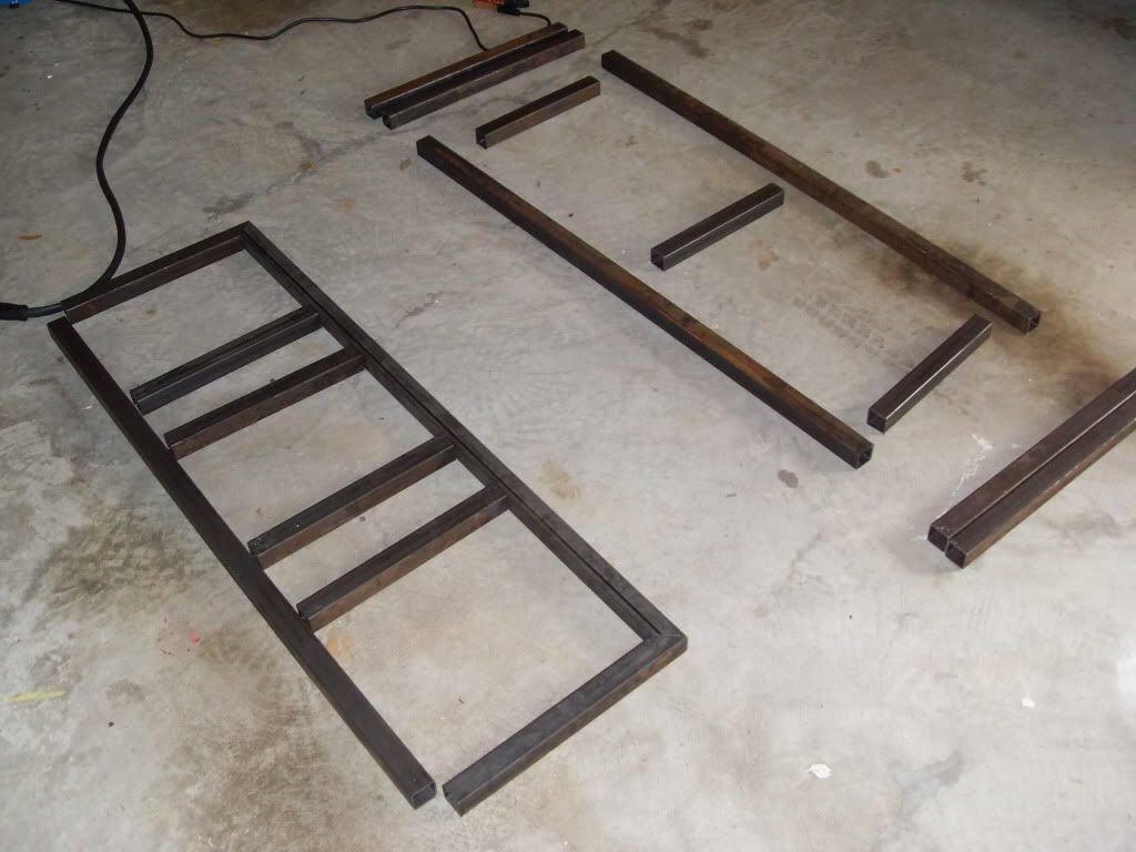
Accumulating the various parts and tools started months ago, but the actual build started on April 6, 2012. I went with 16 gauge 1.5" mild steel for the build and got it from Metal Supermarkets. I found their prices to by far be the most competitive in the Atlanta area. They were able to cut to my measurements for about $0.45 per cut - a bargain. The total cost with cuts was around $75. I also must say that after speaking with both of their Atlanta locations on the phone, I found the Doraville location to be much easier to deal with than the Marietta location.
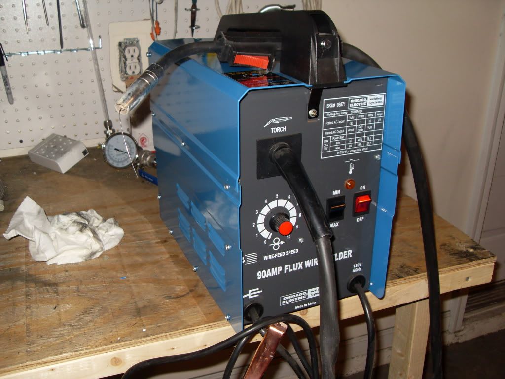
Per the input of one of countless threads I came across here I picked up Harbor Freight's Chicago Electric 90 Amp Flux Wire Welder for I think around $100. I just sold it tonight on Craigslist for $80. I would say I got my $20 out of it. For anyone considering learning to weld on the Brutus and choose to use the same welder, I will give you a piece of advice I wish I had when starting. Use the Min power setting and set the wire speed to around 8 or 9. After burning more than my fair share of holes in the stand when the wire feed was set at 1 and the power was on Max, I found salvation. All the previously created holes were easily filled on the faster feed setting.
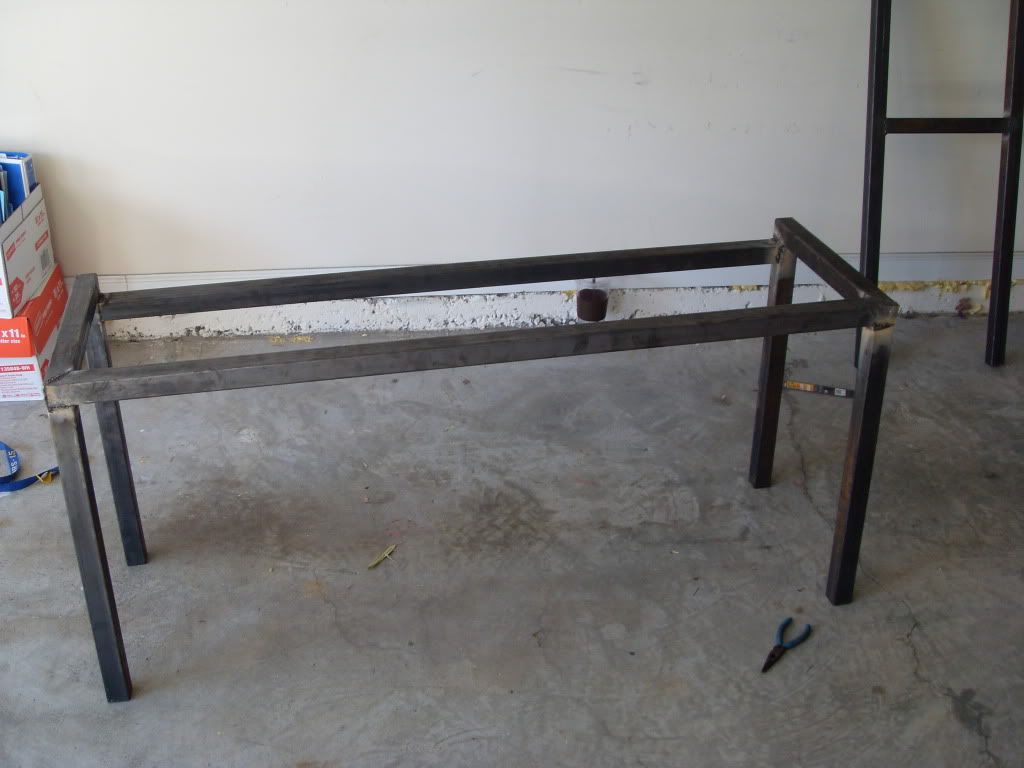
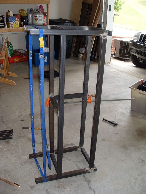
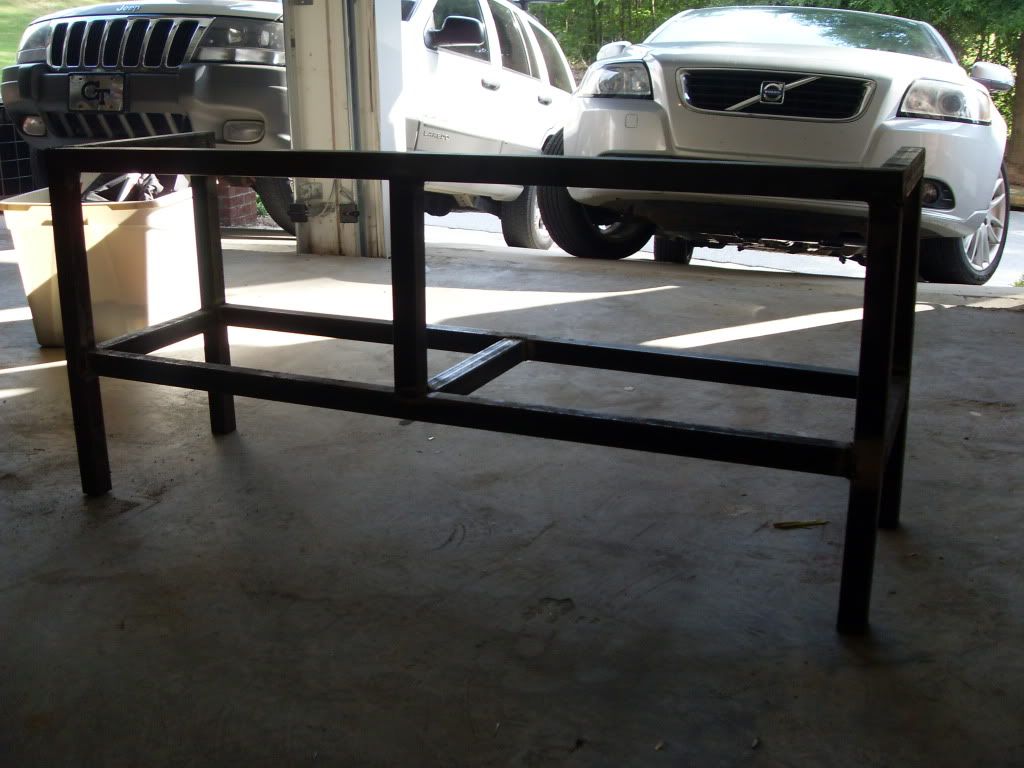
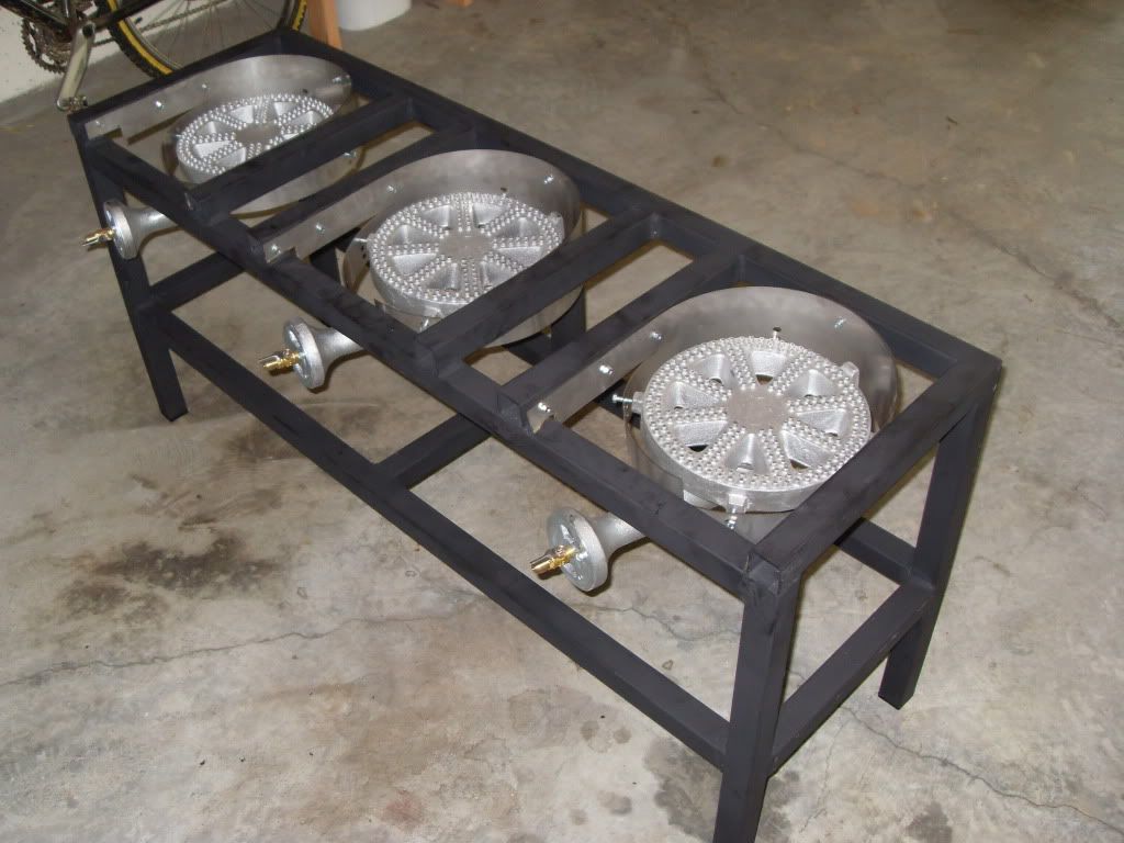
Countless hours spent over the first weekend welding the stand out and battling to keep it square.
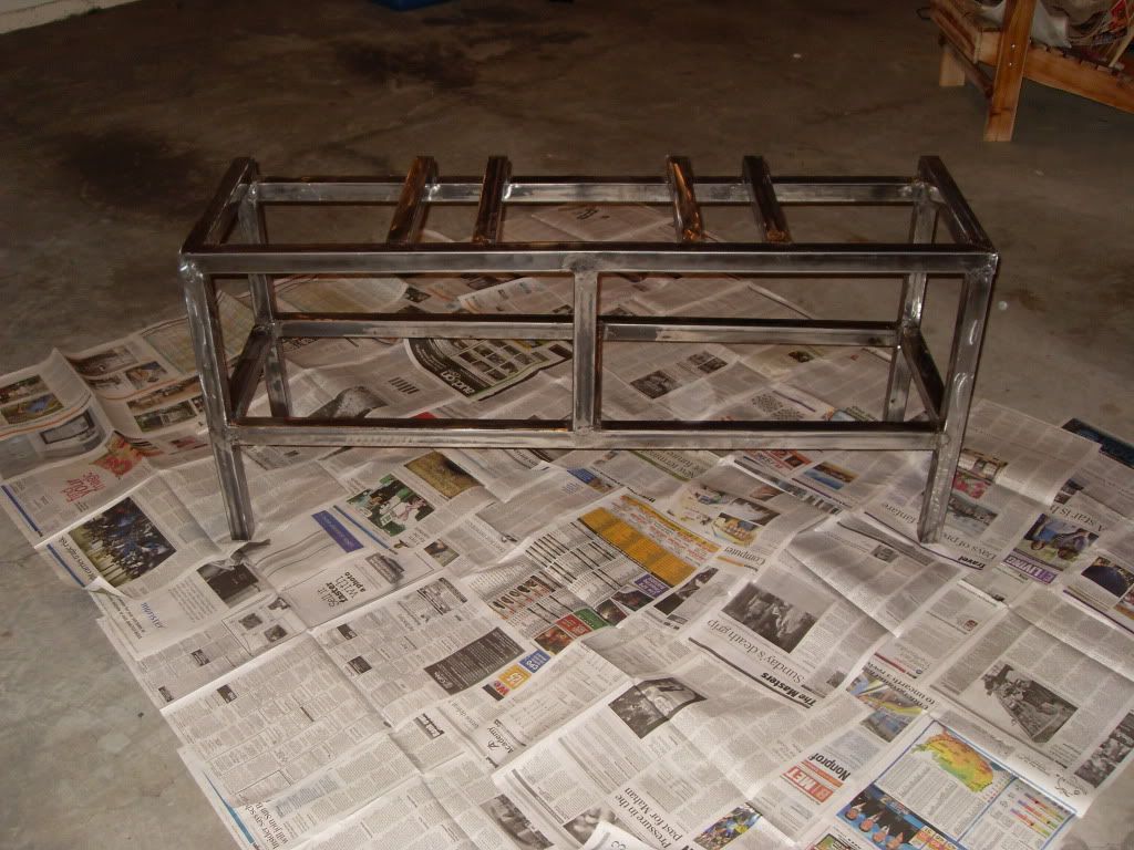
Now onto the fun part, grinding, grinding, grinding. I took a metal grinding disc to all the welds and later an 80 grit flap disc over the entire stand. I would put the over under of times that my garage smoke detector went off in this process at 10. Each of the 10 was equally annoying to my wife upstairs as when one detector goes off in the house, they all do.
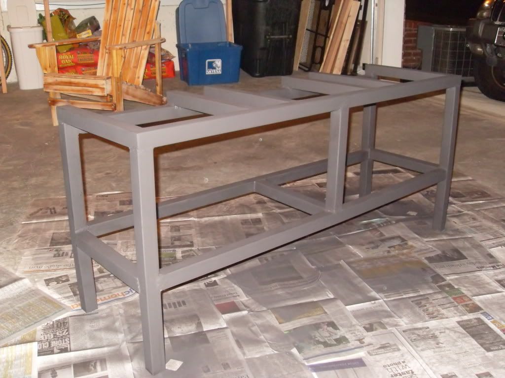
I opted for the Rustoleum Grill Paint from HD. The header paint colors and gloss did entice me, but at the end of the day the need to cure those paints prevented me from going down that road. Between the spray paint residue and the ground metal lets just say my garage was pretty dusty/dirty.
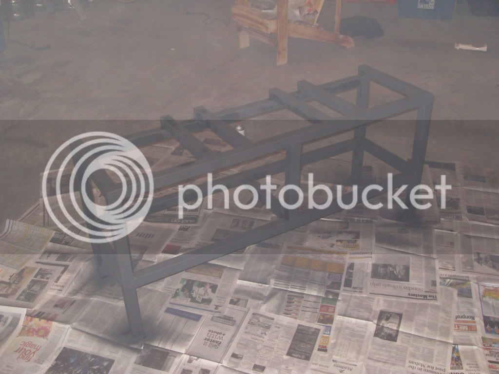
After opening the garage door to allow the fumes/excess paint to vent the stand began to look pretty good.
I picked up the Brewer's Hardware Banjo Burner Heat Shields to mount my burners as I really liked the design that allows venting from the rear. These are designed for a stand with 2" steel so I had to notch out the rear with a cut off disc on my angle grinder to fit on my 1.5" stand. I also opted to mount the burners to the stand with self tapping sheet metal screws. This was a bit of controversy as to whether or not these would hold on an earlier thread I stared on the topic, but I have got to say that I don't see these screws ever failing. The reason I went with the screws is because I was told that my welder was not capable of attaching these stainless mounts to my stand.
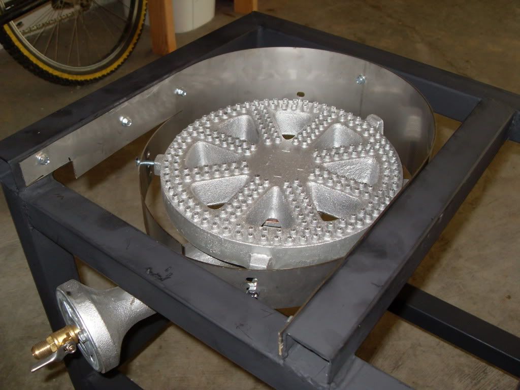
If anyone else is planning on using the Brewer's Hardware Mount you will need to pick up longer screws as the short screws that come with the Banjo Burners will not create a large enough diameter for the shield to wrap around.
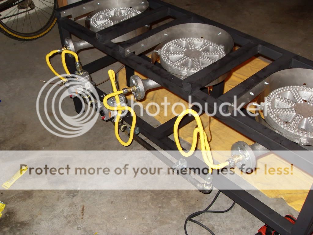
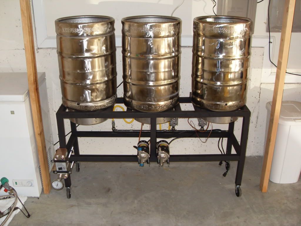
The plumbing and mounting of my valves and pilots was pretty straightforward. I chose to rely on the orifice valve (low pressure propane also picked up from Brewers Hardware) instead of plumbing in needle valves.
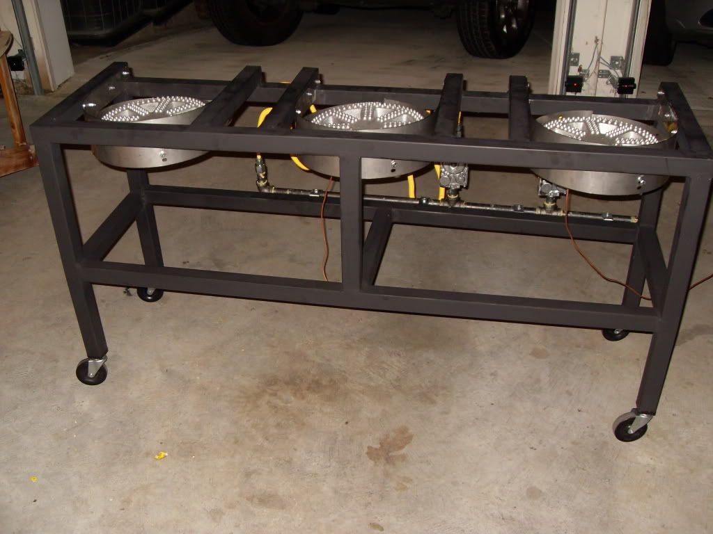
For casters I went with McMaster Carr threaded inserts and casters. I chose this over attempting to weld a nut to the inside of the leg as I didn't trust my welding skills to do that and could see the caster falling off in the middle of a brew day.
To mount my plate chiller and pumps I made plates out of a piece of flat iron I picked up from HD that I used to clamp the items to the stand. This was by far the simplest solution that will allow flexibility in the future and holds super strong with lock washers.
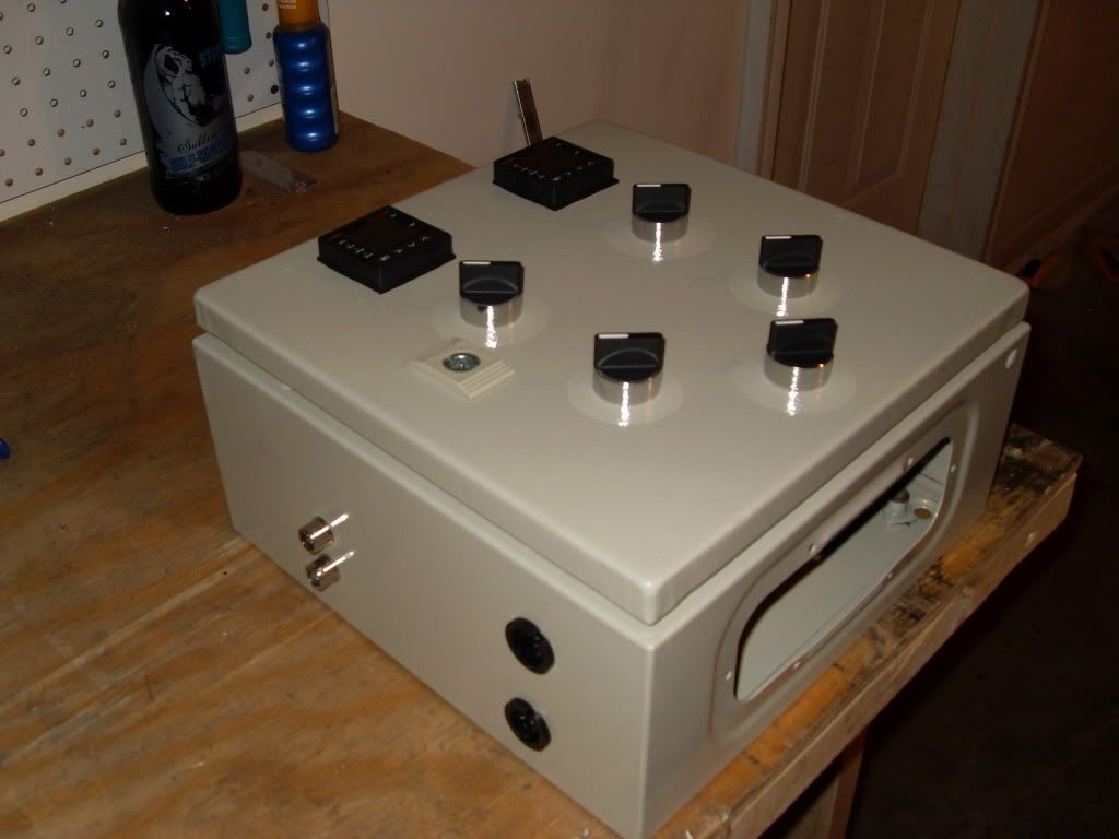
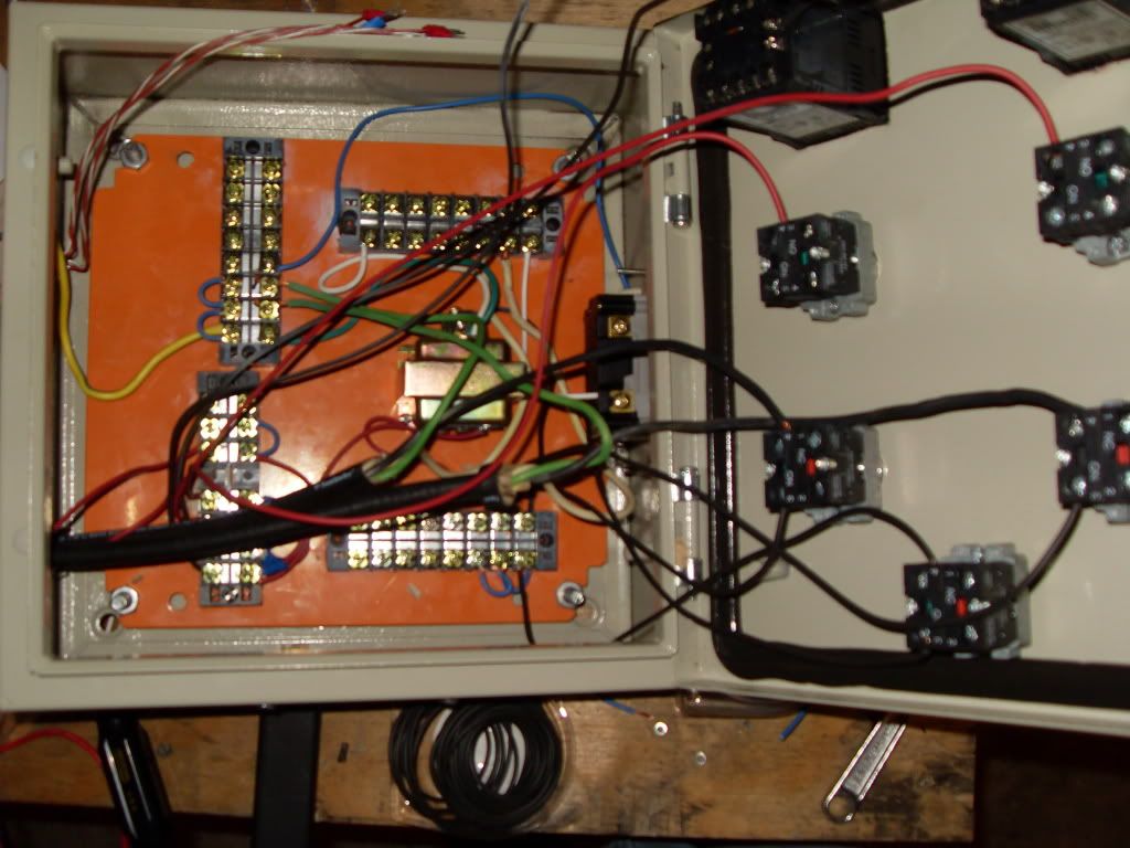
Next up was the most challenging part of the build... the control panel. I felt by far that documentation around control panel builds was the most lacking on HBT. I saw plenty of panels I wanted to replicate, but didn't know where to begin as there were no threads I found with detailed descriptions of the various components involved. For instance a terminal strip, I saw plenty of pictures and could tell what it did, but didn't have the first idea what it was called. Thanks to Collinsbrew's documentation and some great members of the forum I am almost there on the panel. I just need to figure out the setting on my PID.
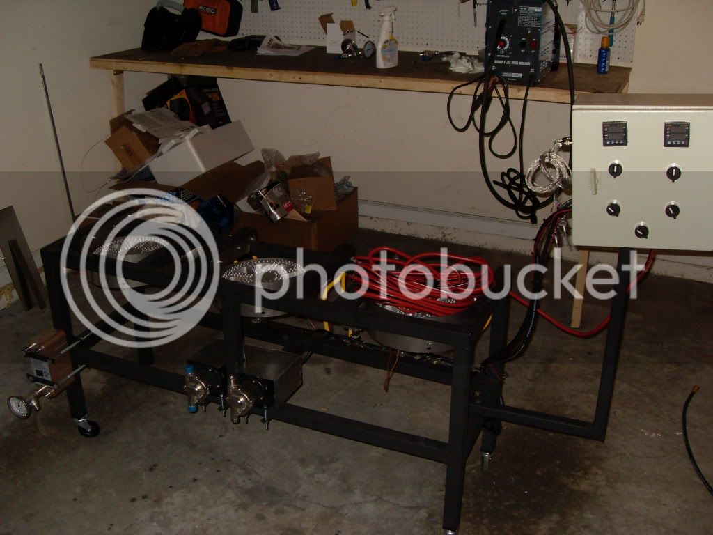
The control panel mount was very simple. I simply made an L and attached it to my stand with a bolt through the two pieces.
I am getting there and am most definitely on the downhill. The hours spent on this thing are way more than I ever imagined, but after 2.5 weeks I am think I can see the finish line.
Thanks to everyone for helping this idiot out!
*Reserved for final photo*
Accumulating the various parts and tools started months ago, but the actual build started on April 6, 2012. I went with 16 gauge 1.5" mild steel for the build and got it from Metal Supermarkets. I found their prices to by far be the most competitive in the Atlanta area. They were able to cut to my measurements for about $0.45 per cut - a bargain. The total cost with cuts was around $75. I also must say that after speaking with both of their Atlanta locations on the phone, I found the Doraville location to be much easier to deal with than the Marietta location.
Per the input of one of countless threads I came across here I picked up Harbor Freight's Chicago Electric 90 Amp Flux Wire Welder for I think around $100. I just sold it tonight on Craigslist for $80. I would say I got my $20 out of it. For anyone considering learning to weld on the Brutus and choose to use the same welder, I will give you a piece of advice I wish I had when starting. Use the Min power setting and set the wire speed to around 8 or 9. After burning more than my fair share of holes in the stand when the wire feed was set at 1 and the power was on Max, I found salvation. All the previously created holes were easily filled on the faster feed setting.
Countless hours spent over the first weekend welding the stand out and battling to keep it square.
Now onto the fun part, grinding, grinding, grinding. I took a metal grinding disc to all the welds and later an 80 grit flap disc over the entire stand. I would put the over under of times that my garage smoke detector went off in this process at 10. Each of the 10 was equally annoying to my wife upstairs as when one detector goes off in the house, they all do.
I opted for the Rustoleum Grill Paint from HD. The header paint colors and gloss did entice me, but at the end of the day the need to cure those paints prevented me from going down that road. Between the spray paint residue and the ground metal lets just say my garage was pretty dusty/dirty.
After opening the garage door to allow the fumes/excess paint to vent the stand began to look pretty good.
I picked up the Brewer's Hardware Banjo Burner Heat Shields to mount my burners as I really liked the design that allows venting from the rear. These are designed for a stand with 2" steel so I had to notch out the rear with a cut off disc on my angle grinder to fit on my 1.5" stand. I also opted to mount the burners to the stand with self tapping sheet metal screws. This was a bit of controversy as to whether or not these would hold on an earlier thread I stared on the topic, but I have got to say that I don't see these screws ever failing. The reason I went with the screws is because I was told that my welder was not capable of attaching these stainless mounts to my stand.
If anyone else is planning on using the Brewer's Hardware Mount you will need to pick up longer screws as the short screws that come with the Banjo Burners will not create a large enough diameter for the shield to wrap around.
The plumbing and mounting of my valves and pilots was pretty straightforward. I chose to rely on the orifice valve (low pressure propane also picked up from Brewers Hardware) instead of plumbing in needle valves.
For casters I went with McMaster Carr threaded inserts and casters. I chose this over attempting to weld a nut to the inside of the leg as I didn't trust my welding skills to do that and could see the caster falling off in the middle of a brew day.
To mount my plate chiller and pumps I made plates out of a piece of flat iron I picked up from HD that I used to clamp the items to the stand. This was by far the simplest solution that will allow flexibility in the future and holds super strong with lock washers.
Next up was the most challenging part of the build... the control panel. I felt by far that documentation around control panel builds was the most lacking on HBT. I saw plenty of panels I wanted to replicate, but didn't know where to begin as there were no threads I found with detailed descriptions of the various components involved. For instance a terminal strip, I saw plenty of pictures and could tell what it did, but didn't have the first idea what it was called. Thanks to Collinsbrew's documentation and some great members of the forum I am almost there on the panel. I just need to figure out the setting on my PID.
The control panel mount was very simple. I simply made an L and attached it to my stand with a bolt through the two pieces.
I am getting there and am most definitely on the downhill. The hours spent on this thing are way more than I ever imagined, but after 2.5 weeks I am think I can see the finish line.
Thanks to everyone for helping this idiot out!

