• Please visit and share your knowledge at our sister communities:
  • If you have not, please join our official Homebrewing Facebook Group!

    Homebrewing Facebook Group

Adapting existing system for automation

Homebrew Talk

Help Support Homebrew Talk:

This site may earn a commission from merchant affiliate links, including eBay, Amazon, and others.

EyeofdaHawk

Well-Known Member
Joined
Jul 30, 2017
Messages
56
Reaction score
20
Location
Canberra
Howdy peeps

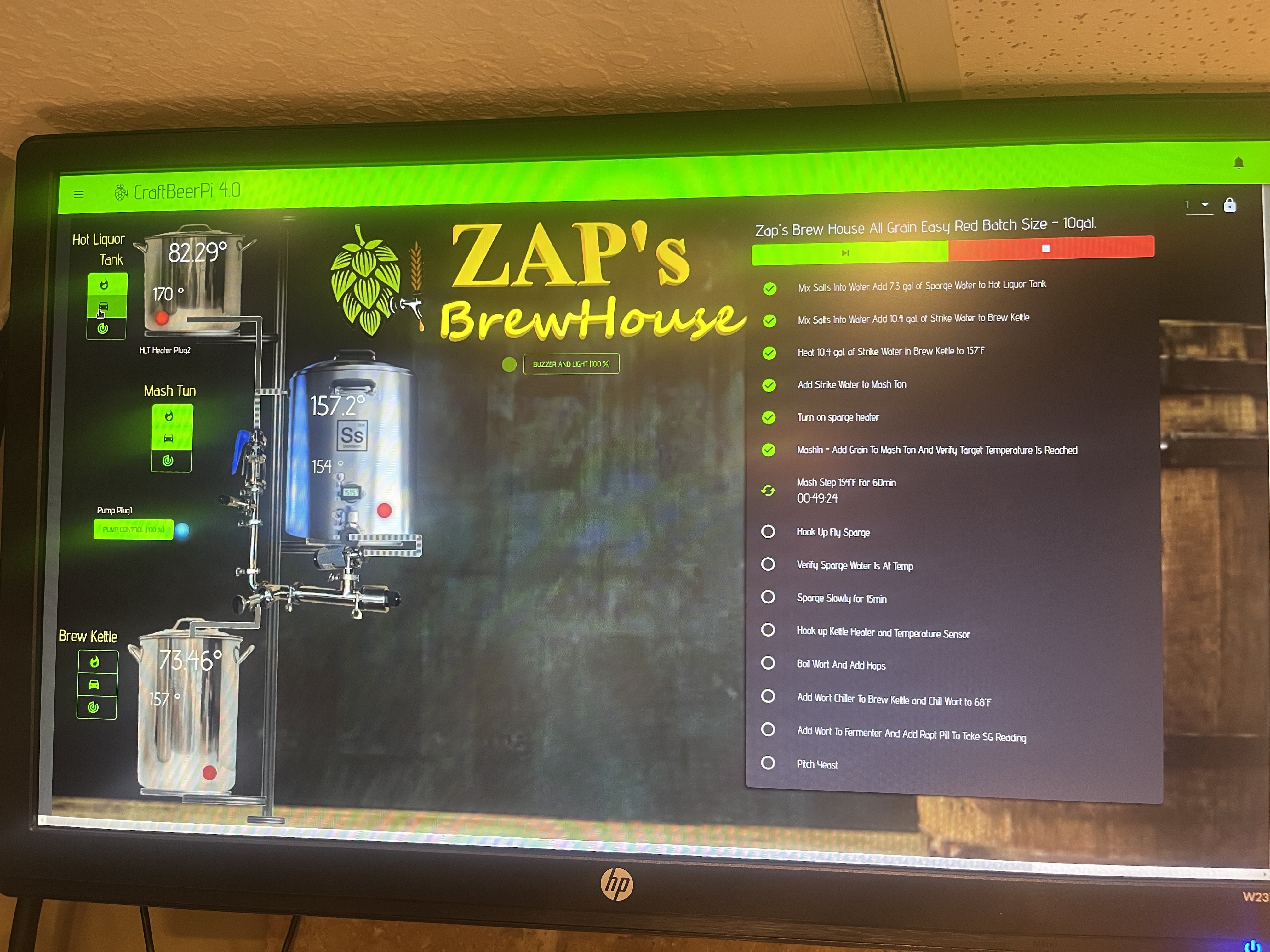
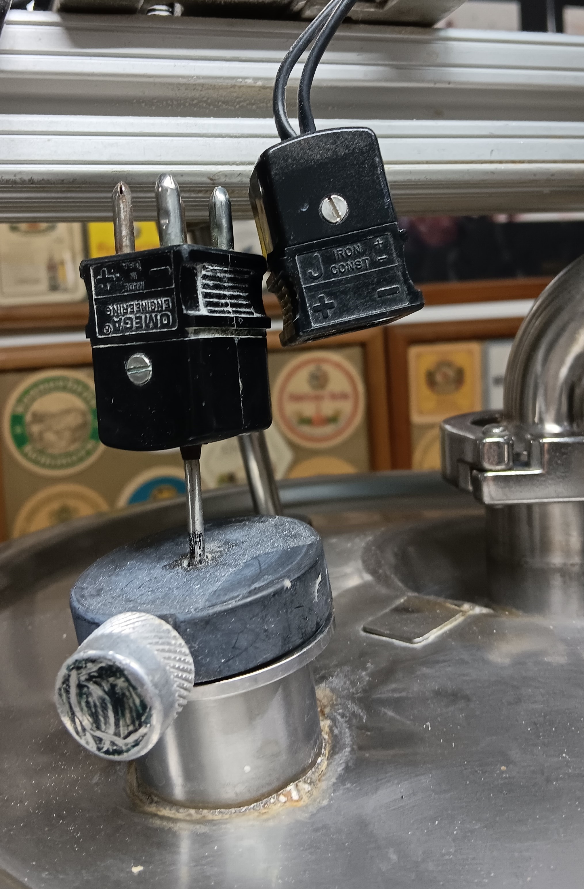
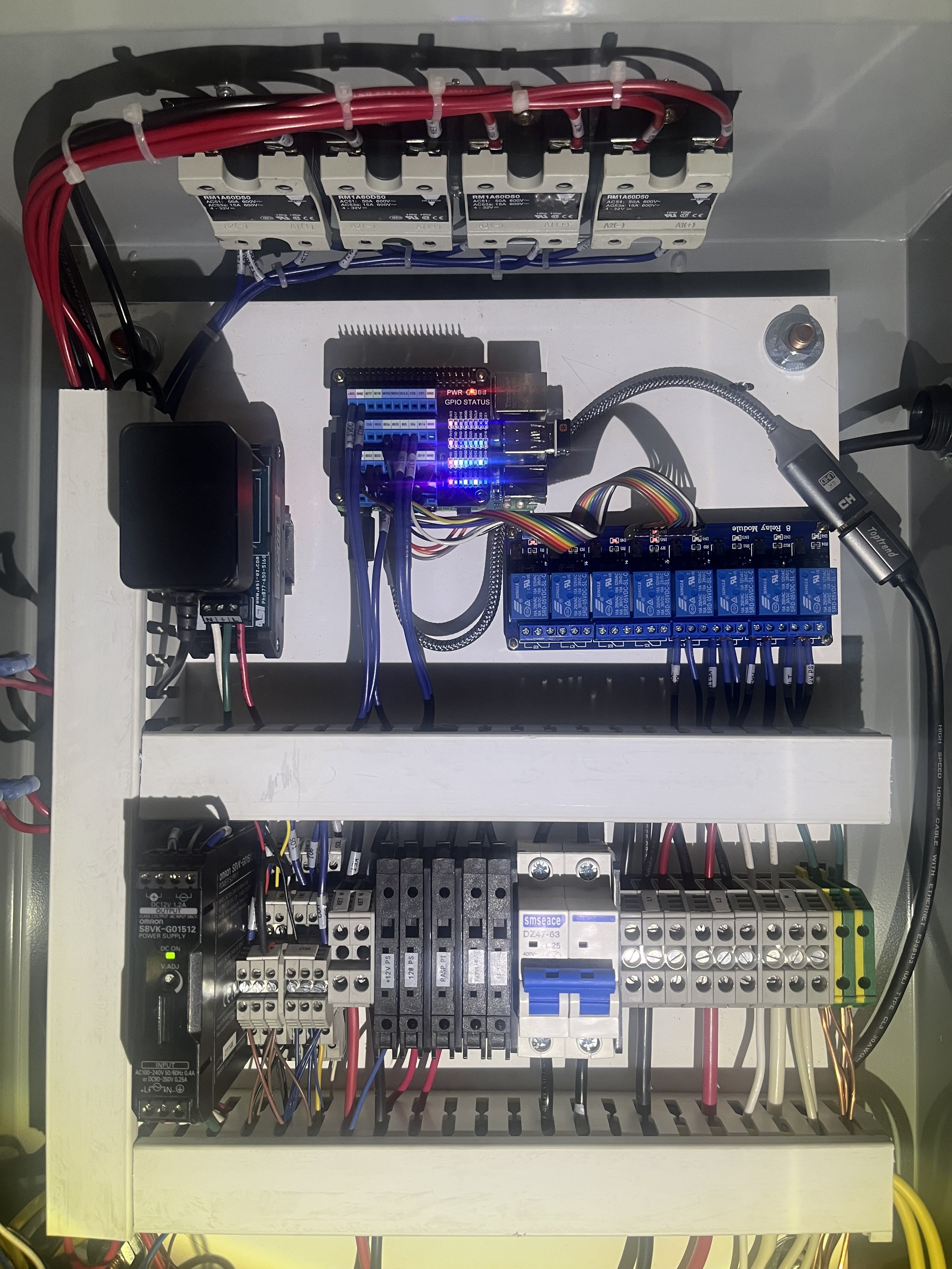
I'm keen to know if i can use adjust my existing system to add in automation (via Rasberry Pi - maybe craftbeerpi). I understand it would require essentially a new control board and that's no issue. What i wonder is can i use the existing SSR, the PIDs, etc. I plan on getting a bunch of these so i can remotely control the valves.

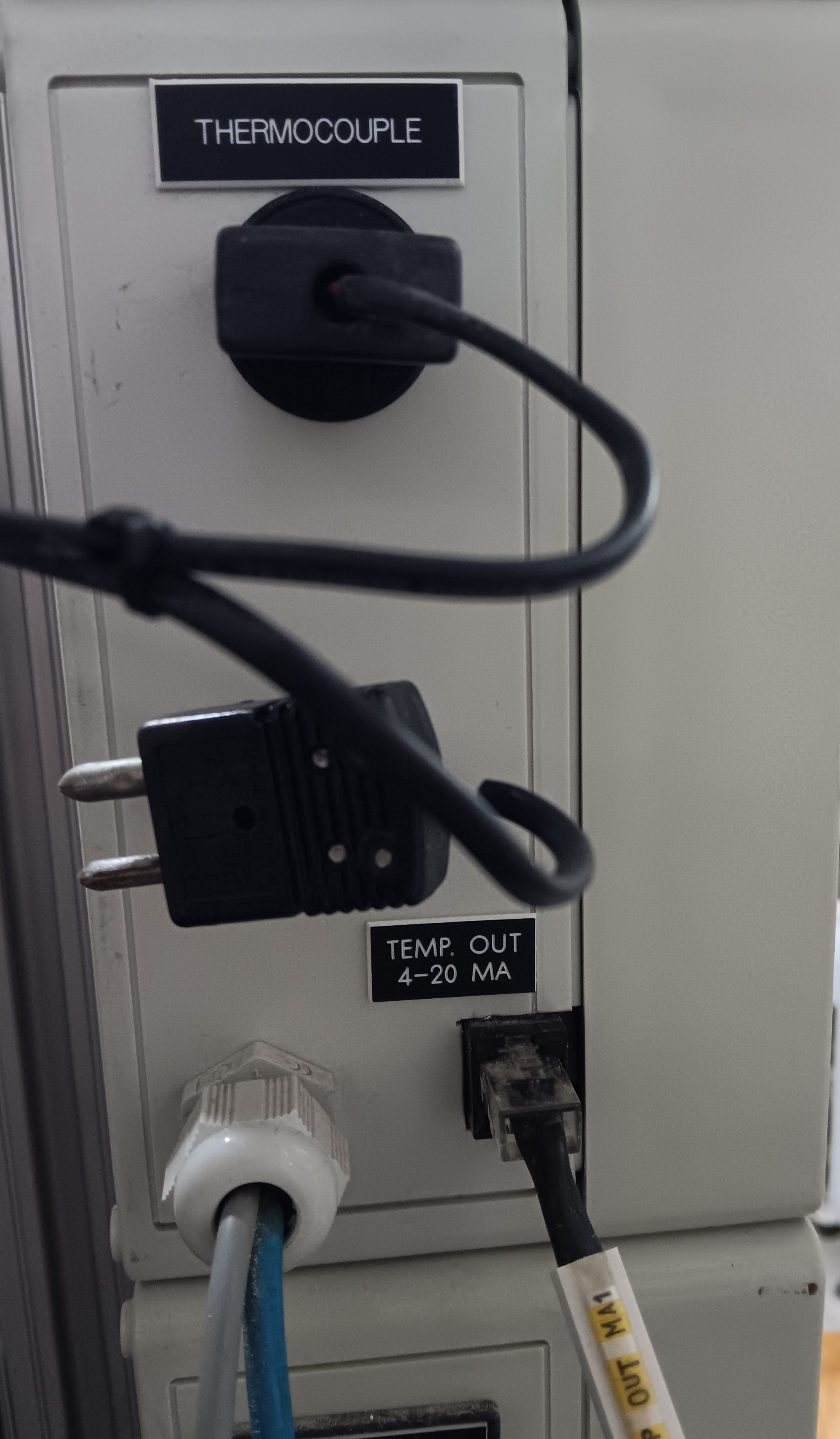
Main question is can i control the PIDs, and thus the power to the elements (2x 6kw - 240v), or would i need to bypass them? I also wonder if i could plug into the 'auto' side of the pumps.

Effectively i need a new project and this is one i've been mulling over for some time.

Cheers
Hawk
 
"These" are not found...
1751162506434.png
 
If you are trying to adapt your existing controller you would be bypassing the PIDs entirely. You would take the RTD signals into your controller via some form of amplifier Example one.

Or punt the existing temperature sensors and go to DS18b20 based ones which can be brought in digitally.

And from there you would take the signal wires going to the SSRs which fire the heating elements and plug those into the outputs on your controller. The rest of the power managment should be fine. You'd want to leave all the manual switches and contactors in place so that you have manual permissives, and shutdowns.
 
Thanks for your response.

Like the idea of reusing the SSRs, not too fussed about bypassing the PIDs, but it i would also like to use the existing temp (as well as more i'd add). Would be great if i can continue using the PIDs, but only as temp displays.

So for the temp sensing side, i'd need a rasberry pi controller, at least one DS18B20, or some other. Would i just connect the element controller into the relevant SSD?

And finally for motorized ball valves (i'll probably have like 9-10), would they also need a dedicated board or could they go straight into the rasberry PI?

This has been the most complicated bit for me, understanding the hardware requirements before i dive into the coding maze.

Thanks
Hawk
 
It's unlikely a motorized ball valve can be controlled directly from an RPi due to the voltage & current typically used - I'm seeing 12VDC and up as high as 120VAC, with currents as high as 1.2 amps. An RPi can't handle any of that directly so some type of interfacing would be required...

Cheers!
 
It's unlikely a motorized ball valve can be controlled directly from an RPi due to the voltage & current typically used - I'm seeing 12VDC and up as high as 120VAC, with currents as high as 1.2 amps. An RPi can't handle any of that directly so some type of interfacing would be required...

Cheers!
good to know.

You able to share interfaces that would work for this?
 
I think you'd be better off using power mosfets like this one https://www.adafruit.com/product/355 driving one of the many 9 to 12 volt DC motorized ball valves I've come across - which tend to specify around 5 watts max power draw (which would be nearly an half ampere at 12V). There should be circuit descriptions out there on how to switch an n-channel mosfet from a 3.3V control source (eg: Raspberry Pi GPIO pin) for that type of application...


Cheers!
 
Awesome thanks.

I'll try map all this out and would really appreciate your thoughts. I'm beginning to feel my system will be rather complicated, compared to most others (as i've really struggled to find the hardware mapping here). But i've got time to sort it out and love learning new things (currently learning Spanish - muy lentamente!)
 
Thanks for your response.

Like the idea of reusing the SSRs, not too fussed about bypassing the PIDs, but it i would also like to use the existing temp (as well as more i'd add). Would be great if i can continue using the PIDs, but only as temp displays.

So for the temp sensing side, i'd need a rasberry pi controller, at least one DS18B20, or some other. Would i just connect the element controller into the relevant SSD?

And finally for motorized ball valves (i'll probably have like 9-10), would they also need a dedicated board or could they go straight into the rasberry PI?

This has been the most complicated bit for me, understanding the hardware requirements before i dive into the coding maze.

Thanks
Hawk
"Like the idea of reusing the SSRs, not too fussed about bypassing the PIDs, but it i would also like to use the existing temp"
You may not have a PID with communication capabilities.
I use my PIDs as process thermometers during normal operation only. Every brewing station has a PID. The PIDs have a 4-20mA output and transmit the process temperature to the brewery controller for processing. During normal operation, the PID is in remote and all the heating is done by the controller with the same circuitry. During a controller failure, the PID can take over by switching to local mode. All the required circuitry will be connected to the PID to continue the process. Has worked great for me for over 30 years.

PID.jpg
 
Awesome thanks.

I'll try map all this out and would really appreciate your thoughts. I'm beginning to feel my system will be rather complicated, compared to most others (as i've really struggled to find the hardware mapping here). But i've got time to sort it out and love learning new things (currently learning Spanish - muy lentamente!)
The motor valves say 3 wire control. That may need more than one output from the controller.
Normally them have 3 states, closed, open left, open right. Even open both on some valves.
Most PID do not have communication link, so you may not hook them to the system.
 
I'm a fast learning, and i put my original electric brewery based controller together myself. I got a electrician to wire it up and check it though.

At this stage i'm limiting the scope of my investigation to hardware, including circuits. I want to make sure it remains consistent with any controlling software, including brucontrol, but that's next stage.

I've found also no support on what hardware is needed to actually get into the automation space, hence the questions.

But yes, i am very new to all this, hence the number of questions.
 
The motor valves say 3 wire control. That may need more than one output from the controller.
Normally them have 3 states, closed, open left, open right. Even open both on some valves.
Most PID do not have communication link, so you may not hook them to the system.
By controller do you mean the rasberry pi, or my existing system?

My current plan would be to wire the existing temp (not the additional ones) from my PIDs, in such a way they the PIDs can still indicate temp, to the rasberry pi controller circuit. I think i'll have to remove the PID connection to SSR wiring and get that into the rasberry pi circuit, as i am not confident on having it via a switch, although i could be convinced.
Why don't you want to buy an additional temperature probe for the controller and leave the PID's probe connected?
 
Raspberry PI, Craft Beer Pi was a solid way to go here, I am still learning Craft Beer Pi myself. My suggestion use a relay board to keep from overloading the PI. I don't have with the valves, but will be interested to see what you come up with.
 
Why don't you want to buy an additional temperature probe for the controller and leave the PID's probe connected?
Don't want to drill any/too many more holes into my SS vessels.

I've otherwise pulled together a bit of a parts list. So far concluded i'd need 3 x cheese boards, 3 relays (for the pumps, must be able to handle 20W), like 12 valve controllers (IN4001), and maybe 3 N-channel Power MOSFET things, plus 4x PT100 RTD and 2 more DS18B2V for the the temp probes.

I've got all this drawn up on paper, just not sure how to easily map it. Thinking of just snipping the relevant bits and drawing lines between them in word or power point. Issue is the circuit drawers don't have pre-drawn circuits for the PT100 RTDs, or relays.

Any suggestions on this would be appreciated.

Other roadblock i've found is i can only by 1 motorized ball valve at a time!
 
CraftBeerPi has temps available for display on the screen. There’s no reason to keep your old controllers for temp display. I would build a new panel and ditch the old PID controllers but use the SSR’s. PID control is very functional in the craftbeerpi program.
 

Attachments

  • IMG_0646.jpeg
    IMG_0646.jpeg
    1.8 MB
Don't want to drill any/too many more holes into my SS vessels.

I've otherwise pulled together a bit of a parts list. So far concluded i'd need 3 x cheese boards, 3 relays (for the pumps, must be able to handle 20W), like 12 valve controllers (IN4001), and maybe 3 N-channel Power MOSFET things, plus 4x PT100 RTD and 2 more DS18B2V for the the temp probes.

I've got all this drawn up on paper, just not sure how to easily map it. Thinking of just snipping the relevant bits and drawing lines between them in word or power point. Issue is the circuit drawers don't have pre-drawn circuits for the PT100 RTDs, or relays.

Any suggestions on this would be appreciated.

Other roadblock i've found is i can only by 1 motorized ball valve at a time!
"Don't want to drill any/too many more holes into my SS vessels." I may have a solution for you. Replace the current temp sensor with a dual-element sensor. You connect one to your PID and one to your controller. I have dual-element temp sensors on all important brewing stations as backup in case of failure.
My dual sensors are thermocouples. RTDs are available in different configurations, too.
 

Attachments

  • 20250709_180025.jpg
    20250709_180025.jpg
    1 MB
  • 20250709_181821.jpg
    20250709_181821.jpg
    912.6 KB
CraftBeerPi has temps available for display on the screen. There’s no reason to keep your old controllers for temp display. I would build a new panel and ditch the old PID controllers but use the SSR’s. PID control is very functional in the craftbeerpi program.
" There’s no reason to keep your old controllers for temp display." For redundancy, it's a great idea. In case of automation failure, he switches back to PID control. All or most of the old components may work with the automation, too. Redesigning the circuit gives him both options.
 
I suppose that would be an option for redundancy but I was under the impression that he just wanted the old temp controls for display only. I’ve had few problems with my setup. If I have a thermocouple not reading right I have spares ready to swap out. It only takes a minute to readdress the input. I double check temps with a mechanical thermometer in my mash tun. I like to try and think ahead and have what I need if things do fail though.
 
Thanks for all the suggestions. I'm going to try smash out a circuit design this weekend. If i could keep my existing controller functional that would be great. I only got it like 1 year ago!
 
Ok, so i'll swallow my pride here. This **** be hard.

Seriously struggling to get needed components to go into autodesk. Yep, might be a hurdle too high.

However, i am not done yet. Question is, now that i have more or less worked out the specs, is there anywhere/one i talk to get it designed/built?

Understand it probably won't be free, but thinking that is my only avenue. I really want this output, just short of taking a month long lesson in autocad probably won't get there on my own.

Hawk
 
Maybe I missed something in the thread but why are you going to build circuits with bread boards and components to run your valves? There are relay modules that interface with the RPi IO hat board. You should be able to run your valves and SSR’s with them. The module I use has 10amp relays. Here’s a pic of my controller maybe it will shed some light light on your setup.
 

Attachments

  • IMG_0731.jpeg
    IMG_0731.jpeg
    2 MB
Maybe I missed something in the thread but why are you going to build circuits with bread boards and components to run your valves? There are relay modules that interface with the RPi IO hat board. You should be able to run your valves and SSR’s with them. The module I use has 10amp relays. Here’s a pic of my controller maybe it will shed some light light on your setup.
Congratulations on your clean-looking panel.
 
Maybe I missed something in the thread but why are you going to build circuits with bread boards and components to run your valves? There are relay modules that interface with the RPi IO hat board. You should be able to run your valves and SSR’s with them. The module I use has 10amp relays. Here’s a pic of my controller maybe it will shed some light light on your setup.
I wanted to make it fully automatically controllable. Like be able to watch and control it all from my office. Would need all those extra bits for the valves, pumps, temp probes. Ergo the need of somewhere to mount them all.
 
I wanted to make it fully automatically controllable. Like be able to watch and control it all from my office. Would need all those extra bits for the valves, pumps, temp probes. Ergo the need of somewhere to mount them all.
"Like be able to watch and control it all from my office." Great. Will you be able to control your brewing system also at the equipment location or only from your office?
 
The CraftBeerPi program is capable of being accessed by remote computers through a web address if you’re on the same network. You can run the system at the equipment and from your office computer or even your phone if set up that way. Just something to keep in mind for your design. Good luck with your project!
 
The CraftBeerPi program is capable of being accessed by remote computers through a web address if you’re on the same network. You can run the system at the equipment and from your office computer or even your phone if set up that way. Just something to keep in mind for your design. Good luck with your project!
And , if you add zerotier One to the rpi and you phone/tablet you can control from anyware.
 
Ok, so i'm continuing with this project, but plz.... excuse me for the simplicity of the initial diagram. I know it is missing a lot, but i'm just trying to sort out the initial requirements. This would be my temp wiring. The PT-100's would take the cables from the existing PIDs and put that into the RPi, the DS18b20 would be new temp probes (which i already have) which go directly into there, and then into the RPi.

I understand a lot of other wiring would be required, but this is just a start. Couple of initial questions. I figure i'm going to run out of space on the RPi, as i still need pump and valve control. So figure i'd need a central board. No idea how this works presently, can anyone point me in that direction.

As for the RPi, what power would that need? I figure my pumps would need their own power source, as they are all 240V and the RPi would just be a simple on/off and so not need that much power. Any suggestions on that front? Looks like the Latching Mini Relay FeatherWing may work as the relay, but not sure how to get that to the RPi. Also guessing i'd need 3 as i have 3 pumps.

So know i'm way out of my depth, but hoping i can get some help from the brains trust.

Hawk

1752574369830.png
 
modulo-adaptador-lcd-a-i2c-pcf8574.jpg
For the outputs you may use a relay board as ZapperMike shows in the picture.
The pt100 interfaces are SPI, so they need 3 wires plus a CS por each one.
The relays could be connected to port expanders. I use i2c LCD interface to drive an 8 relay board.
They are cheap and easy to find. They are PCF8574 in deed.
DS18B20 don’t need a pin for each one. The data line will read as many as 8 or 10. Depends of the wire length. They work better as a bus and not a wire for each one from de controller.
 
Last edited:
Back
Top