• Please visit and share your knowledge at our sister communities:
  • If you have not, please join our official Homebrewing Facebook Group!

    Homebrewing Facebook Group

AC gycol chiller build Q...

Homebrew Talk

Help Support Homebrew Talk:

This site may earn a commission from merchant affiliate links, including eBay, Amazon, and others.
Those help a whole lot. The way this is wired when the 'controller' decides that it wants cooling it energizes the blue wire. Thus the high level test involves taking off the blue wire, attaching a voltmeter between the pin you took it from (on the board) and neutral (or ground) and adjusting the controller (temperature set point) to a value well lower than the room temperature. Before disconnecting the blue wire find the overload and make sure it is closed (reads 0 ohms across its terminals).

Lowering the thermostat setting should cause the thermostat to close and the controller to put voltage on the blade to which the blue wire connects. If this does not happen then the controller or transformer is defective. About all you can do from there is check the transformer.

If the controller does put voltage on the blue wire pin then it is working properly and you can proceed to check the cap. There are two sections: 5 and 25 uFd. Remove the wires from the cap before testing it but be sure to make notes or take pictures to allow you to get the wires back onto the right terminals. This is critical. If the cap passes then move on to check the compressor winding resistances. Check between the ends (at the capacitor) between the blue wire and the black wire and between the blue wire and the red wire. You should get a reading of a few ohms for each. The blue/red reading should be higher than the blue/black reading. A reading of OL or infinity for both would suggest the overload is open in which case you should double check that.
 
Thank you so much!! Sorry my bd today so didnt get to it...so does C mean compressor? Will do this tomorrow when I get home...
I will mention one of the black wires on cap came off...not sure exactly which spot it goes back in...there are two terminals that it can go...it goes to a black round thing up top...thermostat?


Those help a whole lot. The way this is wired when the 'controller' decides that it wants cooling it energizes the blue wire. Thus the high level test involves taking off the blue wire, attaching a voltmeter between the pin you took it from (on the board) and neutral (or ground) and adjusting the controller (temperature set point) to a value well lower than the room temperature. Before disconnecting the blue wire find the overload and make sure it is closed (reads 0 ohms across its terminals).

Lowering the thermostat setting should cause the thermostat to close and the controller to put voltage on the blade to which the blue wire connects. If this does not happen then the controller or transformer is defective. About all you can do from there is check the transformer.

If the controller does put voltage on the blue wire pin then it is working properly and you can proceed to check the cap. There are two sections: 5 and 25 uFd. Remove the wires from the cap before testing it but be sure to make notes or take pictures to allow you to get the wires back onto the right terminals. This is critical. If the cap passes then move on to check the compressor winding resistances. Check between the ends (at the capacitor) between the blue wire and the black wire and between the blue wire and the red wire. You should get a reading of a few ohms for each. The blue/red reading should be higher than the blue/black reading. A reading of OL or infinity for both would suggest the overload is open in which case you should double check that.
 
Well happy birthday!

'C' stands for "Common". Both the compressor and capacitor have terminals marked this way. In the compressor the two windings (S - start and R - run) are connected together at one end and that connection goes to the common terminal. The free ends go to, respectively, the R and S terminals. In the capacitor can one terminal from each of the two individual capacitors in the can are connected together and to the common terminal. The other sides of the capacitors go to, respectively, the FAN and HERM terminals.

There are, apparently, three black wires going to the capacitor. Two are from a start assist which appears to be under the transformer in the photo. The two wires from that go to the capacitor C terminal and the other to the capacitor HERM terminal. The third black wire comes from the R (run) winding on the compressor. It also connects to the C terminal on the capacitor. This is the one that goes to the "black round thing up top" which I am assuming is the thing to which the red, black and blue wires all run together, the thing with S, C and R molded into the top, the left of two cylinders on top of the compressor. That's not the thermostat. That's where the wires enter the compressor through a glass hermetic seal.

In summary, there are 3 terminals on the capacitor. One is labeled "FAN" and should have a single wire of color "TM", whatever that means - it appears to be yellow in the photo. The second is labeled "C" and should have a white wire running from it to the fan motor, a black wire running to the R terminal on top of the compressor and another black wire running to the circuit board start assist. The third terminal is labeled "HERM" and should have a single red wire running from it to the S terminal on the top of the compressor.
 
Thank you SO MUCH for all this...
I did want to say the loose wire I found goes to the black round thing in the wiring pic... at the left hand side, there are two of them and they both go to the Cap...I "think" i put it back but am not sure... will look more in detail this afternoon and do some troubleshooting...

again thank you so much for all this!!

Well happy birthday!

'C' stands for "Common". Both the compressor and capacitor have terminals marked this way. In the compressor the two windings (S - start and R - run) are connected together at one end and that connection goes to the common terminal. The free ends go to, respectively, the R and S terminals. In the capacitor can one terminal from each of the two individual capacitors in the can are connected together and to the common terminal. The other sides of the capacitors go to, respectively, the FAN and HERM terminals.

There are, apparently, three black wires going to the capacitor. Two are from a start assist which appears to be under the transformer in the photo. The two wires from that go to the capacitor C terminal and the other to the capacitor HERM terminal. The third black wire comes from the R (run) winding on the compressor. It also connects to the C terminal on the capacitor. This is the one that goes to the "black round thing up top" which I am assuming is the thing to which the red, black and blue wires all run together, the thing with S, C and R molded into the top, the left of two cylinders on top of the compressor. That's not the thermostat. That's where the wires enter the compressor through a glass hermetic seal.

In summary, there are 3 terminals on the capacitor. One is labeled "FAN" and should have a single wire of color "TM", whatever that means - it appears to be yellow in the photo. The second is labeled "C" and should have a white wire running from it to the fan motor, a black wire running to the R terminal on top of the compressor and another black wire running to the circuit board start assist. The third terminal is labeled "HERM" and should have a single red wire running from it to the S terminal on the top of the compressor.
 
OK so Blue wire is hot, check.
Blue red is 5 ohms blue black is 1.8 ohms
Cap i have not checked yet... there are 3 terminals on it... which ones do i test with my fluke?

ok one side was 4.9 micro F and the other was open... so i guess thats the bad part.... ?

Those help a whole lot. The way this is wired when the 'controller' decides that it wants cooling it energizes the blue wire. Thus the high level test involves taking off the blue wire, attaching a voltmeter between the pin you took it from (on the board) and neutral (or ground) and adjusting the controller (temperature set point) to a value well lower than the room temperature. Before disconnecting the blue wire find the overload and make sure it is closed (reads 0 ohms across its terminals).

Lowering the thermostat setting should cause the thermostat to close and the controller to put voltage on the blade to which the blue wire connects. If this does not happen then the controller or transformer is defective. About all you can do from there is check the transformer.

If the controller does put voltage on the blue wire pin then it is working properly and you can proceed to check the cap. There are two sections: 5 and 25 uFd. Remove the wires from the cap before testing it but be sure to make notes or take pictures to allow you to get the wires back onto the right terminals. This is critical. If the cap passes then move on to check the compressor winding resistances. Check between the ends (at the capacitor) between the blue wire and the black wire and between the blue wire and the red wire. You should get a reading of a few ohms for each. The blue/red reading should be higher than the blue/black reading. A reading of OL or infinity for both would suggest the overload is open in which case you should double check that.
 
Last edited:

Attachments

  • capacitor.jpg
    capacitor.jpg
    240.1 KB
Last edited by a moderator:
Yes, you should measure close to 5 uFd between pins C and Fan and close to 25 between pins C and HERM. If you measure open between C and HERM the cap is bad. There is only one thing that bothers me a little here. Is this not a fairly new unit? A cap should last about 5 years. I just had one fail on my heat pump but it has been here st least as long as I have (about 5 years).

Yes, that's the right size cap and I can vouch for the brand. I just installed one of those and it has run for 3 whole hours so we know they last at least that long.

And the compressor winding resistances look good.
 
Yes I barely used it...but it has sat for a few years unused...
When I ran my test it maybe ran 30 min then I stopped once bath got down to 35 or so about a month ago...
Then I built platform and put it and cooler in it and plugged it in...and didnt work...it looks perfectly fine but I guess being open on comp side not..


Yes, you should measure close to 5 uFd between pins C and Fan and close to 25 between pins C and HERM. If you measure open between C and HERM the cap is bad. There is only one thing that bothers me a little here. Is this not a fairly new unit? A cap should last about 5 years. I just had one fail on my heat pump but it has been here st least as long as I have (about 5 years).

Yes, that's the right size cap and I can vouch for the brand. I just installed one of those and it has run for 3 whole hours so we know they last at least that long.

And the compressor winding resistances look good.
 
In all this i forgot the most important question... is there a way to bypass the E control? the BCS is just a basic controller, turning on and off the power to the AC unit itself... like plugging and unplugging it from wall... every time i power it up it goes back to basic idle state... is there a way to bypass this>? if not i may have to not worry about the cap...to keep the temp in the bath a constant temp like 30 degrees etc...

Yes, you should measure close to 5 uFd between pins C and Fan and close to 25 between pins C and HERM. If you measure open between C and HERM the cap is bad. There is only one thing that bothers me a little here. Is this not a fairly new unit? A cap should last about 5 years. I just had one fail on my heat pump but it has been here st least as long as I have (about 5 years).

Yes, that's the right size cap and I can vouch for the brand. I just installed one of those and it has run for 3 whole hours so we know they last at least that long.

And the compressor winding resistances look good.
 
All you have to do to make the compressor run is disconnect the blue wire from the circuit board and apply 120 VAC to it. This should be through a relay rated for the compressor load current which relay is operated by the BCS. If the BCS has internal relays that can handle the compressor load the extra relay isn't necessary. Doing thus takes the A/C unit's internal thermostat out of the picture.

You will still need the 25 uFd capacitor. That's what spins the magnetic field inside the compressor motor. Without it the compressor will not run. Just hum and get hot.
 
So basically I am hot wiring the Comp and the fan correct? The rest of it isnt needed since I want the BCS via a SSR to control the on off of the AC to set the temp correct?

All you have to do to make the compressor run is disconnect the blue wire from the circuit board and apply 120 VAC to it. This should be through a relay rated for the compressor load current which relay is operated by the BCS. If the BCS has internal relays that can handle the compressor load the extra relay isn't necessary. Doing thus takes the A/C unit's internal thermostat out of the picture.

You will still need the 25 uFd capacitor. That's what spins the magnetic field inside the compressor motor. Without it the compressor will not run. Just hum and get hot.
 
If you connect the blue wire to 120 through an SSR controlled by the BCS then you are "hot wiring" just the compressor. The fan will not run when the blue wire is hot unless the unit'd internal controller has told it to. Presumably you would just turn the internal controller off under this arrangement. All control then goes to the BCS.

Now it occurs to me that there is a problem with this. If, for example, there is a brief power interruption obviously the compressor will stop. As soon as the power comes back on the BCS will command it back on right away. This is not a good thing. Starting a compressor right after it stops is very hard on it as it is starting against full or nearly full head pressure. This may have been what failed your cap. The internal controller will not let that happen. It will wait a minute or two after compressor shutdown before it will allow the compressor to be started again. You need to provide this protection to your compressor. I did a little reading on the BCS to the point where I see that it has some ladder diagram control capability. If you can put a timer in there that won't allow compressor startup for two minutes after it has been shut down for whatever reason then put that in there and Bob's your uncle. If you can't do that then I recommend connecting the line side of the SSR not to the line but to the PCB terminal to which the blue wire normally attaches. Set the internal control to as low as it will go so that the internal controller is always asking for compressor except when there has been a recent power interruption but the SSR won't pass the 120 to the compressor unless the BCS is also asking for cooling. This will protect you from power outages and from unplugging the main power source and replugging it but it won't protect against short cycling from the BCS itself. You should really investigate means of doing that from within the BCS.
 
yes there is a control capability in the BCS that wont short cycle the compressor. So silly Q, how do i connect? if i just go to blue wire only comp runs, wouldnt i want the fan to run also?

If you connect the blue wire to 120 through an SSR controlled by the BCS then you are "hot wiring" just the compressor. The fan will not run when the blue wire is hot unless the unit'd internal controller has told it to. Presumably you would just turn the internal controller off under this arrangement. All control then goes to the BCS.

Now it occurs to me that there is a problem with this. If, for example, there is a brief power interruption obviously the compressor will stop. As soon as the power comes back on the BCS will command it back on right away. This is not a good thing. Starting a compressor right after it stops is very hard on it as it is starting against full or nearly full head pressure. This may have been what failed your cap. The internal controller will not let that happen. It will wait a minute or two after compressor shutdown before it will allow the compressor to be started again. You need to provide this protection to your compressor. I did a little reading on the BCS to the point where I see that it has some ladder diagram control capability. If you can put a timer in there that won't allow compressor startup for two minutes after it has been shut down for whatever reason then put that in there and Bob's your uncle. If you can't do that then I recommend connecting the line side of the SSR not to the line but to the PCB terminal to which the blue wire normally attaches. Set the internal control to as low as it will go so that the internal controller is always asking for compressor except when there has been a recent power interruption but the SSR won't pass the 120 to the compressor unless the BCS is also asking for cooling. This will protect you from power outages and from unplugging the main power source and replugging it but it won't protect against short cycling from the BCS itself. You should really investigate means of doing that from within the BCS.
 
In the connection I am proposing the the fan will always be running because the original internal thermostat is never satisfied. Note that comments about the door have been removed. Those pertain to another post - not this one. There is no door here AFAIK.
 
Last edited:
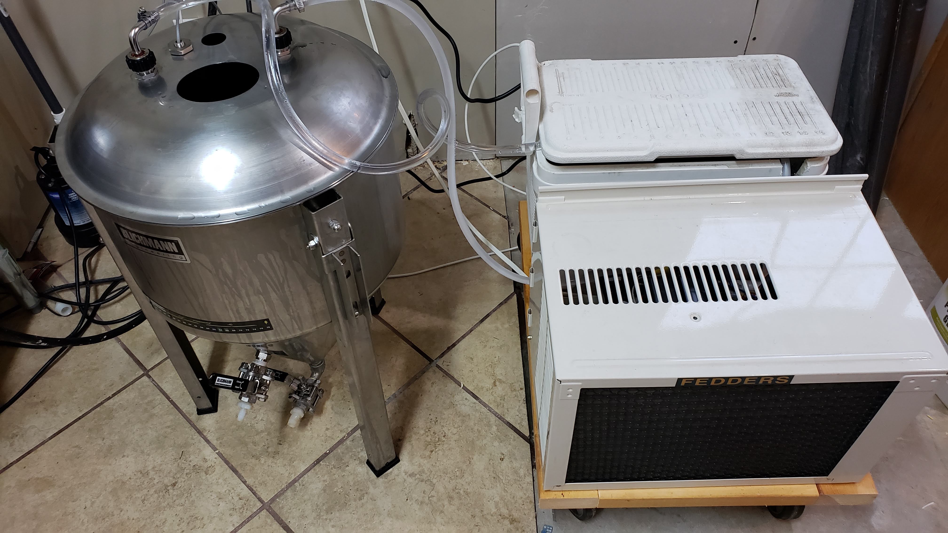
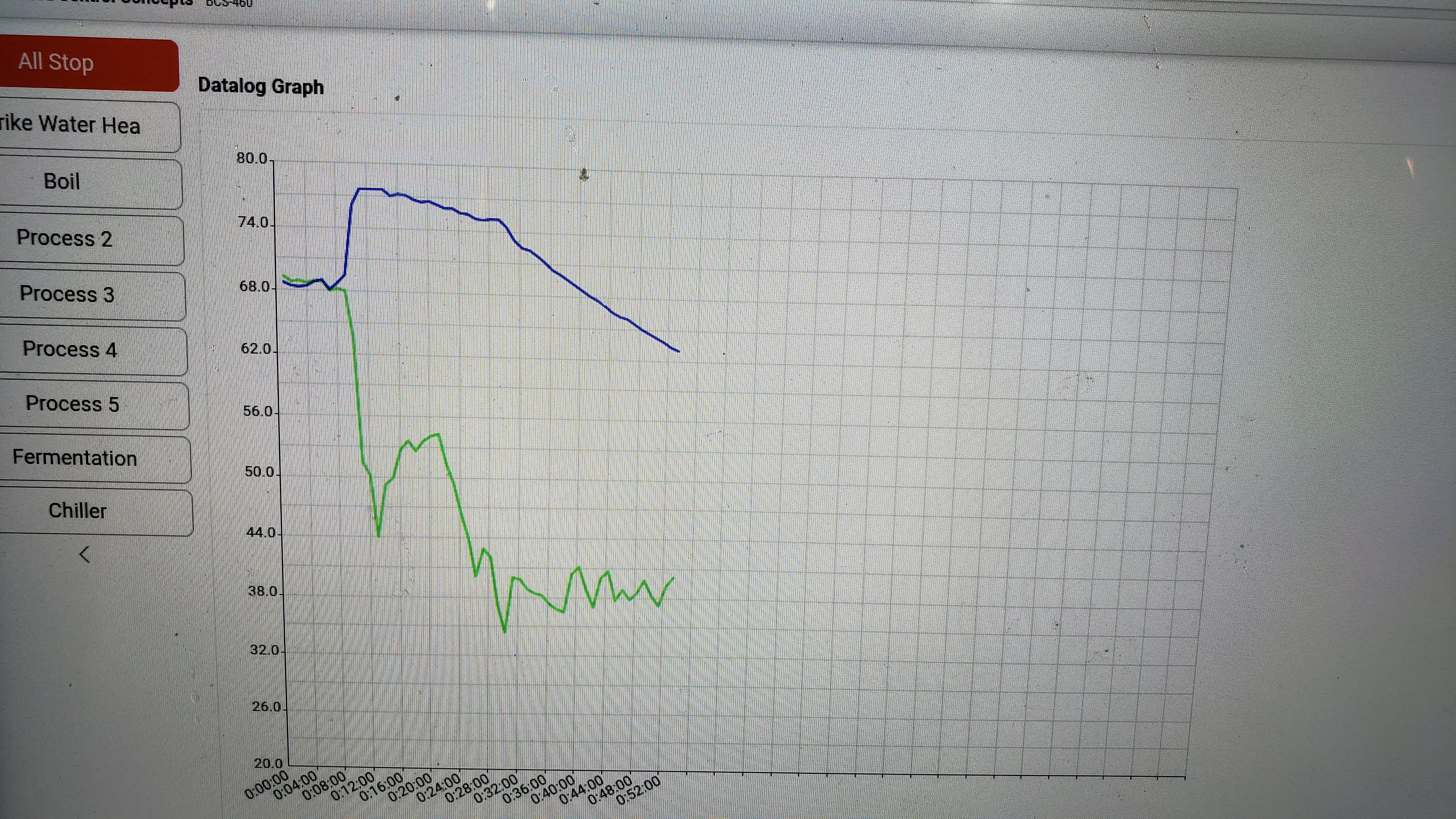
Still waiting on the last temp probe, I used the one from the kettle to test it out though. Worked ok, pump needs to be bigger... barely any flow through the coil... but it cooled down pretty well. It kept wanting to restart a lot until both started to get cold, then they cycling went way down.... got the kettle down to about 44 before i called it a night...

I was surprised how accurate those little strips are on the kettle, it was always very close to what the temp probe inside said, within 1 -2 degrees...

20181010_175856.jpg
20181010_175906.jpg
 
A professional cylindroconical is coaxial with insulation between the inner and outer walls. Is this fermenter built that way? If not you will get a big improvement in chiller performance by wrapping it in insulation. You want to be cooling the beer - not the room air.
 
A professional cylindroconical is coaxial with insulation between the inner and outer walls. Is this fermenter built that way? If not you will get a big improvement in chiller performance by wrapping it in insulation. You want to be cooling the beer - not the room air.

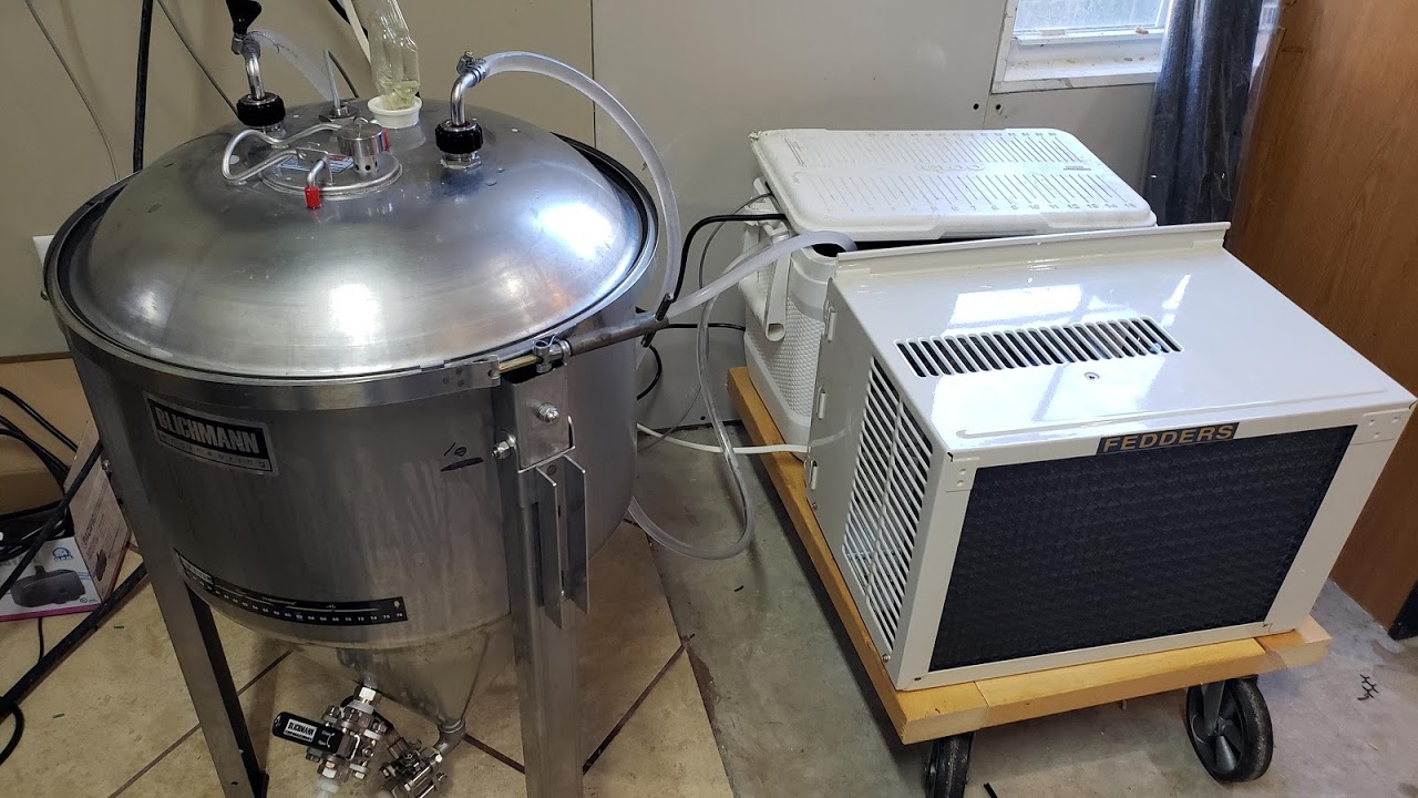
Its a blichman conical, not insulated, and yes I will wrap it in insulation when I am actually fermenting in it... at 44 degrees there was some condensation on the outside of it... i just need a little bigger pump i think... other than that it worked great.

the cycling was way slower when the temp in the F came around 50 degrees... maybe once every 10 min?

thank you for all your help! I couldnt have wired it without your knowledge!
 
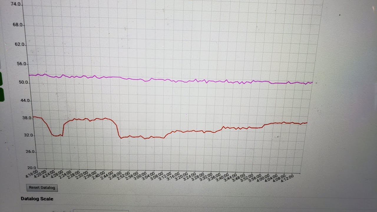
Finally used for the first time yesterday. Brewed a Czech Pilsner... sitting at 52 degrees waiting for starter to finish... so far works great. I did wrap an old comforter about it to keep it cooler...but it kept 52 no prob...
20181021_164900.jpg
20181021_133644.jpg
20181021_164900.jpg
20181021_133644.jpg
 
Back
Top