• Please visit and share your knowledge at our sister communities:
  • If you have not, please join our official Homebrewing Facebook Group!

    Homebrewing Facebook Group

A Brewpi Remix Build

Homebrew Talk

Help Support Homebrew Talk:

This site may earn a commission from merchant affiliate links, including eBay, Amazon, and others.
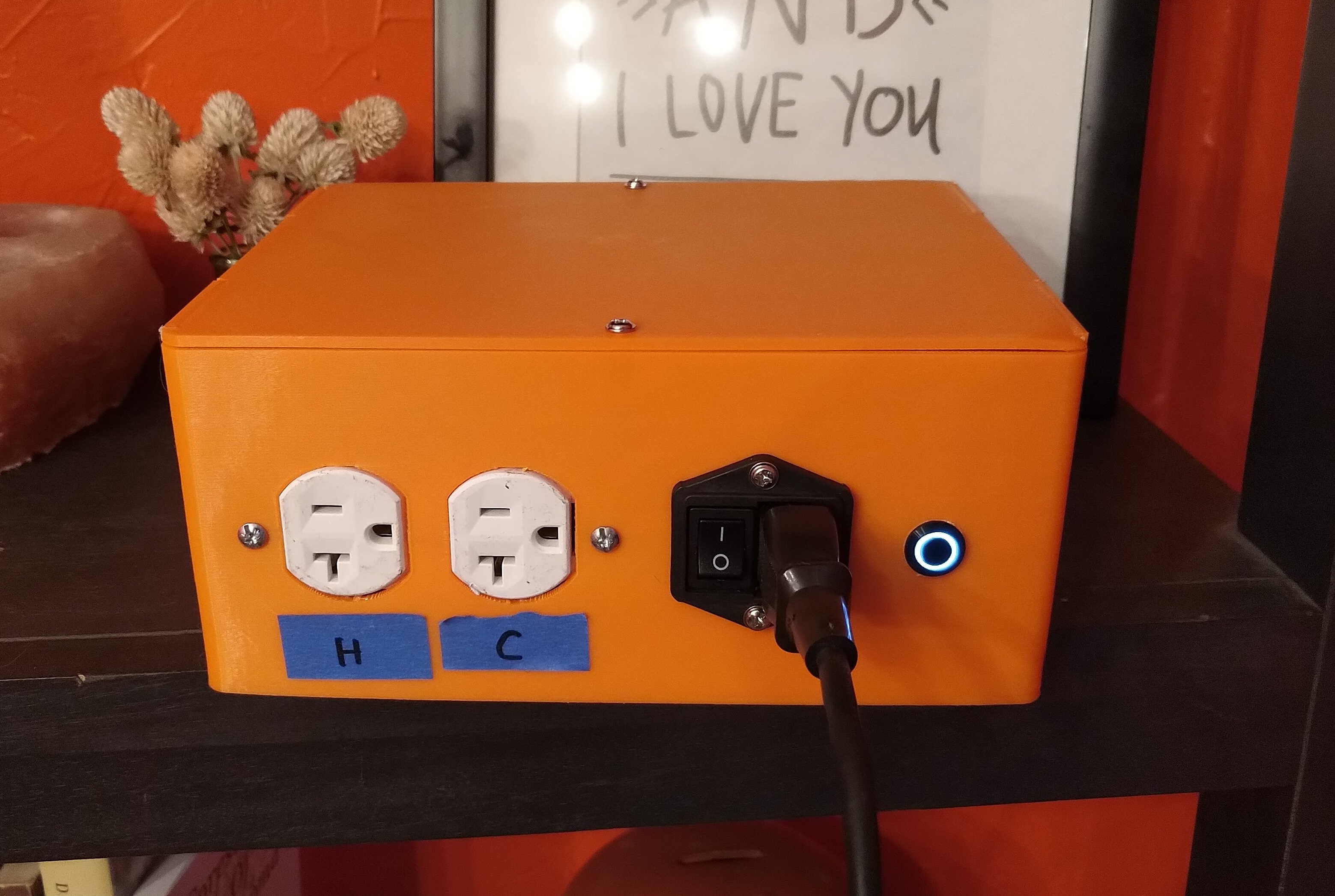
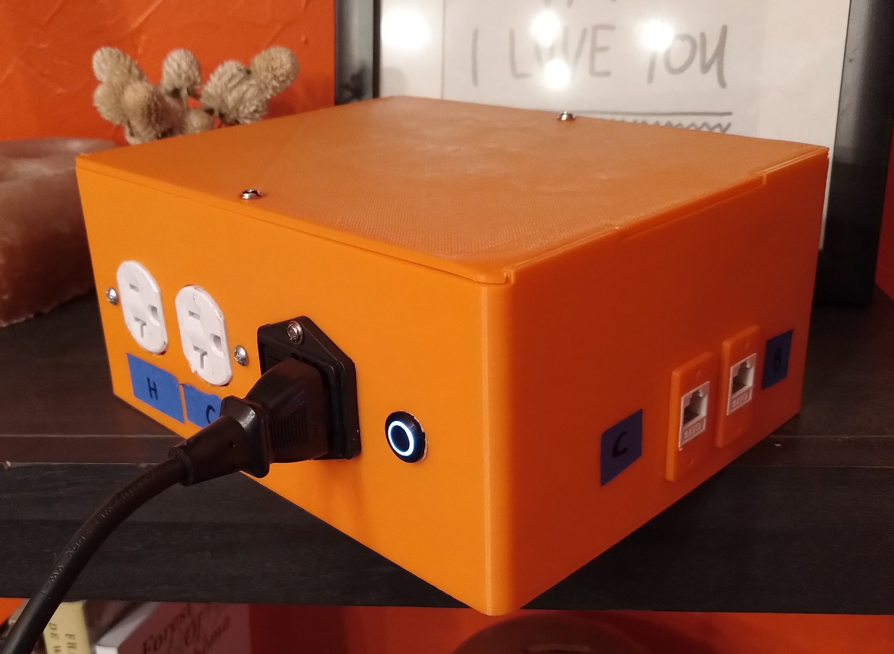
I think I finally got it ready for it's first batch of beer. Finally got a lighted momentary switch for shutdown, and wired the LED to GPIO22 and a ground, and added gpio=22=op,dh to the config.txt file. I'll probably go back in and modify the enclosure design to include Heat and Cool labels for the outlet, as well as Chamber and Beer for the RJ45 jacks, but I'm not going to print it and move everything just for that.

IMG_20201217_170248.jpg


IMG_20201217_170257.jpg


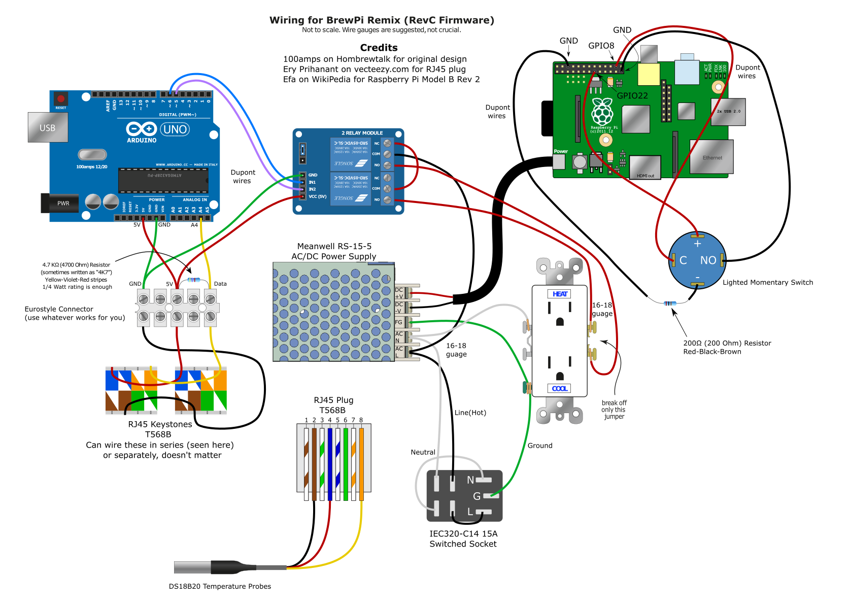
I reached out to @100amps to find out how he made such pretty diagrams for the wiring (Adobe Illustrator for those that are wondering), and he was kind enough to share his latest one, which I then modified using Inkscape to show my own build.
Okie-BrewPI-Remix.png
 
That looks great!

I need to figure out how to design in my supports. That seems to come out much better.

The pushbutton for the Pi is a gamechanger.
 
That looks great!

I need to figure out how to design in my supports. That seems to come out much better.

The pushbutton for the Pi is a gamechanger.

Thanks! This was my first time designing in supports and it was actually pretty easy. This video was helpful for me,
He uses Solidworks, and I use Fusion360, but the concept is the same.

Basically I offset from the bottom of the hole .2mm (or whatever your layer height will be), then extrude to .2mm below the top of the hole, with a 1mm on each side of the support extrusion for easier removal.
 
Is it possible to embed text labels on the surface for those connectors & ports?
Like "Heat" and "Cool" (or at least "H" and "C") above the duplex sockets?

Cheers!
 
Is it possible to embed text labels on the surface for those connectors & ports?
It is - I was trying not to pile on because right now he's looking at those pieces of tape and eventually it will get to him enough to re-make it. :p

The problem is: I'll bet he's got a > 1 day print there. If I were to guess, it's only about $5 in material, but tying up your printer for another day for an H and C is an emotional decision he needs to make. :D
 
Yeah, you need to do something about those H and C labels. The designer in me is screaming. I suggest looking for some red painters tape for the H label. :cool:
 
For the RJ45 jacks it says you can wire them in series like you did. That's actually parallel. But that's nitpicking.
 
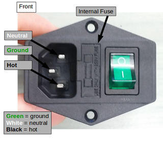
An enhancement I recommend is using a fused IEC power inlet. Say 8-10 amp fuse. But make sure it's one that has legitimate safety certifications. CSA/UL or whatever. The only way to ensure those certs are legit is to buy it from a responsible supplier. (Mouser, Digikey, etc.)

iec.png
 
Is it possible to embed text labels on the surface for those connectors & ports?
Like "Heat" and "Cool" (or at least "H" and "C") above the duplex sockets?

I think the blue painters tape gives it a certian je ne sais quoi ;)

But yeah, it is possible. I'll be modifying the design today to add that in, but probably won't actually print a new enclosure until I need to. I probably should have thought about that before I printed the first one, but I was focused more on getting everything to fit in a box that was small enough to print on my 3d printer, and honestly didn't even think about it at the time.

The problem is: I'll bet he's got a > 1 day print there. If I were to guess, it's only about $5 in material, but tying up your printer for another day for an H and C is an emotional decision he needs to make. :D

Hahaha, exactly. Also after that, taking everything apart and putting it in a new box.

One other option I have is engraving that info on the existing box with a laser cutter/engraver. I have a membership at the local makerspace here in Tulsa called the Fab Lab, and they have a pretty slick laser cutter, so I'll probably go that route.


For the RJ45 jacks it says you can wire them in series like you did. That's actually parallel. But that's nitpicking.

Ah, gotcha. I'll fix it, might throw someone off.

An enhancement I recommend is using a fused IEC power inlet. Say 8-10 amp fuse. But make sure it's one that has legitimate safety certifications. CSA/UL or whatever. The only way to ensure those certs are legit is to buy it from a responsible supplier. (Mouser, Digikey, etc.)
I did get the inlet from DigiKey, but I did not get a fused one. I'll look into adding a fuse to the AC circuit
 
An enhancement I recommend is using a fused IEC power inlet. Say 8-10 amp fuse. But make sure it's one that has legitimate safety certifications. CSA/UL or whatever. The only way to ensure those certs are legit is to buy it from a responsible supplier. (Mouser, Digikey, etc.)
Such as these.
1608593440205.png

Of course, these are $19.25 and Chinese ones can be had for $1.50. :) @day_trippr has often noted the switches on the cheaper ones burning out.
 
Ah, but remember, the bulkheads we all were using were sold as "10 Amp" but sported 6A or even 5A switch modules.
The Holy Grail (post #19) looks strong. I need to get mine installed, just been too busy...

Cheers!
 
I saw a fused IEC inlet (10A) on Digikey.com for like $1.50. I consider the switch optional. I leave mine running or just pull the plug. It's still probably engineered in China, but Digikey almost certainly do their due diligence wrt safety certs.

Of course shipping is on top of that.
 
Lotsa options. For me, the fused is less important than the switch. Pretty sure that relay is going to be my "fuse" before the fuse is. :)
 
Relays do make decent fuses. Sure they smell like burnt plastic, but it's because they're 'cloud based' which means they communicate with your smoke detector to provide you with a convenient wireless notification that your controller may be near some tolerance limit. The word 'fuse' was, in fact, derived from relay contacts permanently fusing together, ensuring an optimal low impedance connection. 😎
 
Last edited:
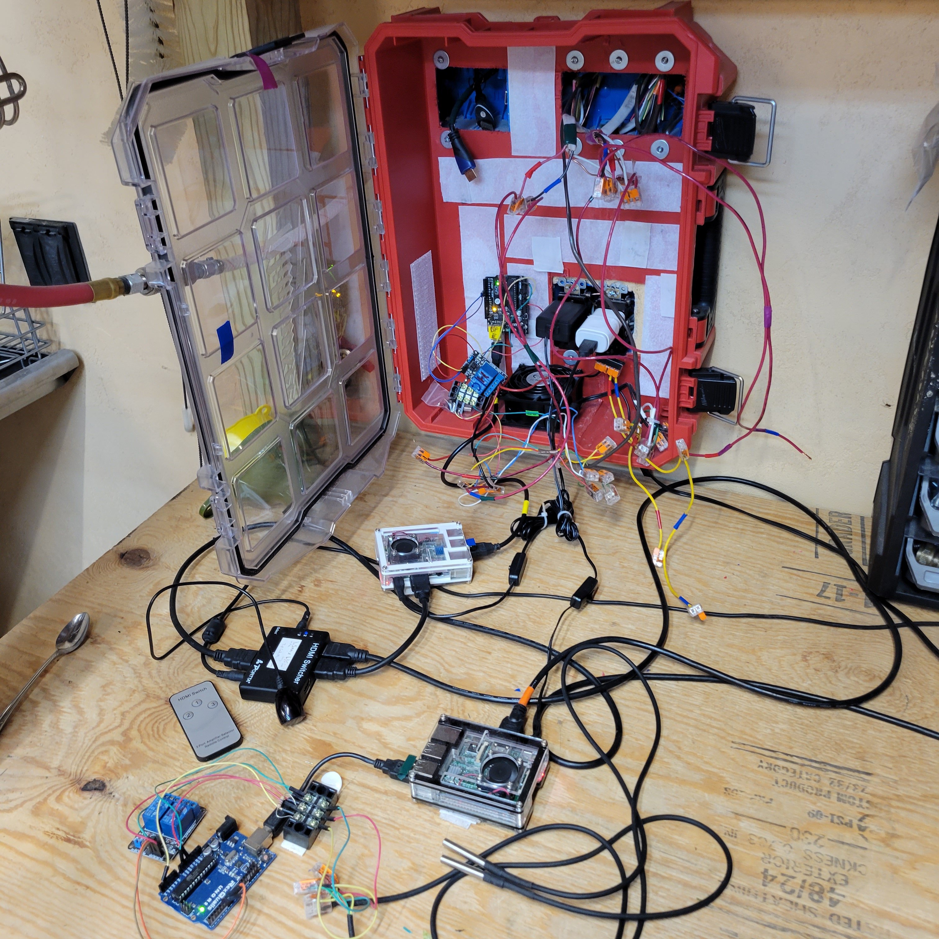
The Milwaukee packout box will someday house 2 smaller boxes that you men have posted here. As an HVAC Tech and a Master Plumber also, I am embarrassed to show you my "Build" LOL
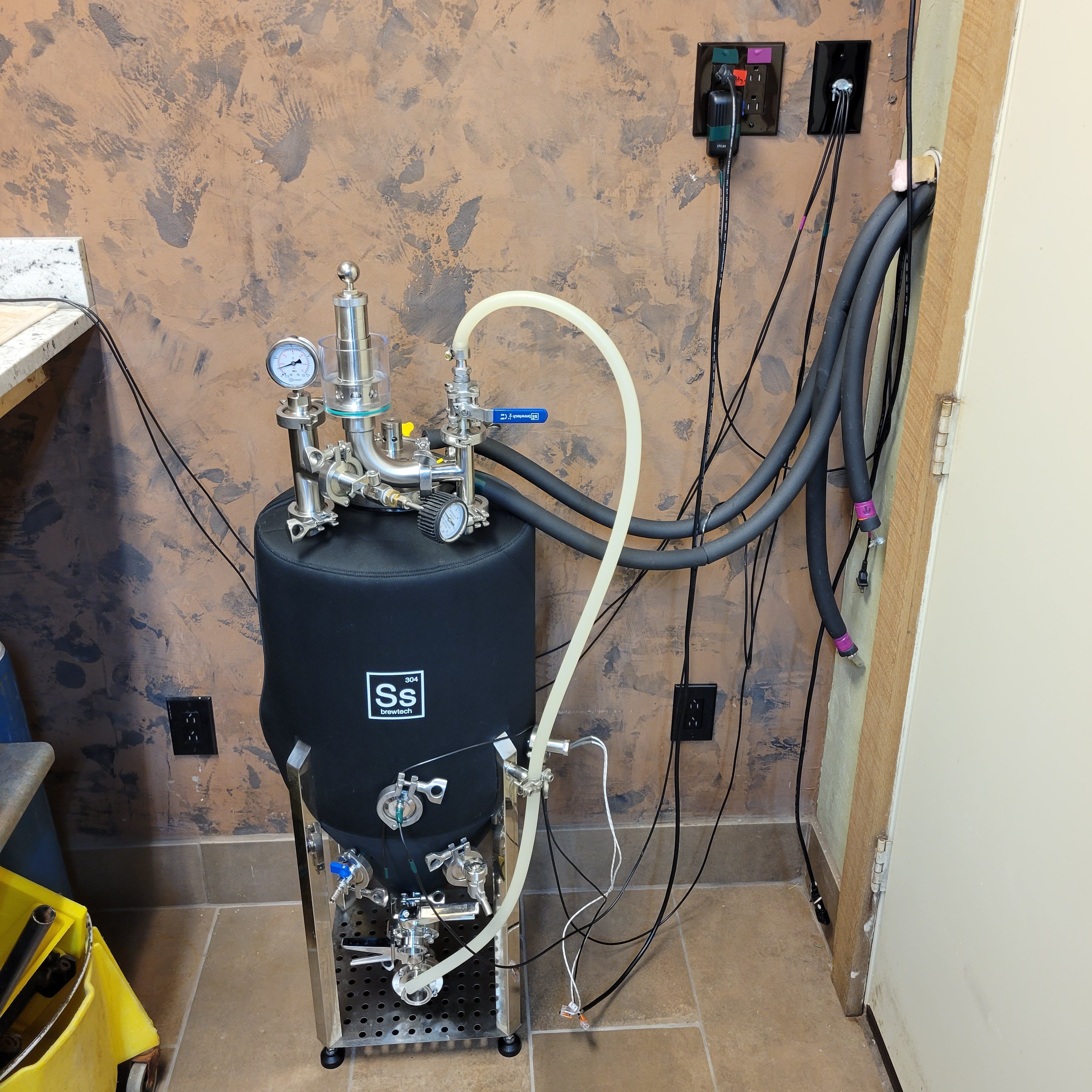
The 1/2 Bbl Unitank is about 20 feet away from this desk, and I ran all the control temperature probe wires and AC power through the walls, around my walk-in-cooler (HVAC... had to have one)
It works! I just need @LBussy help me figure out WTH is going on with the second BPRemix not working
Hopefully I will post my "hack" without a 3D printer (just dremmel, and pipe wrenches... LOL)
The right side has a 300 watt, 110 VAC, heater rod ($17) that I added an additional Triclamp bulkhead onto the tank (works fantastic!)
The Cooling is from a 55 gallon barrel of chilled water inside the cooler, next to the Unitank
If anyone is interested in this tank re-build, just send a message and I will give you all the Where, and How-to
 
No, I am referring to the switched AC bulkhead, as shown in the OP's illustration and outlined here:

View attachment 708978

Sadly, these are consistently mis-represented as "10 AMP" bulkheads even while the switch modules have "6A" molded into their shells...

Cheers!
Where is Dad's Pencil Sharpener in the box?
I am trying to figure out how to mount all my Szit in a nice work-box, and where to buy the boxes, power supply, and support "legs" to run screws into.
 
Back
Top