Chugger Pump Modular Waterproof GFCI Box

Homebrew Talk - Beer, Wine, Mead, & Cider Brewing Discussion Forum

Help Support Homebrew Talk - Beer, Wine, Mead, & Cider Brewing Discussion Forum:

This site may earn a commission from merchant affiliate links, including eBay, Amazon, and others.

SixthGear

Active Member
Joined
Apr 28, 2012
Messages
36
Reaction score
11
Location
Columbus
Hey all,

I just recently decided to upgrade my all grain setup with the addition of a plate chiller and chugger pump. BrewHardware had a great kit/setup for sale that took a little customization for my configuration, but was probably the best bang for the buck out there. Since I saw a few partial guides to setting up a pump and chiller like this, I figured I'd do the full DIY here.

So, step 1 is to source all the parts you need to make the switch box:
8k5jMrPl.jpg


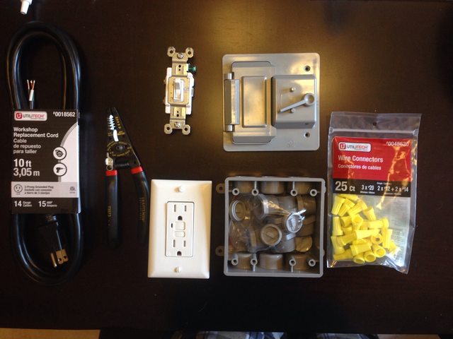
I chose to use a 14ga workshop replacement cord, generic light switch, weatherproof switch and plug cover, GFCI outlet, and a 7 port 2-gang box. I thought I would need wire twists, but it turns out you don't so ignore those. Cost was probably around $30-40 for all the parts, with the GFCI socket being the most expensive ($18 at my local lowes).

User day_tripper has a great wiring guide in this post:
https://www.homebrewtalk.com/f11/march-pump-wiring-switch-outlet-310309/#post3859204
1pYqmLg.jpg


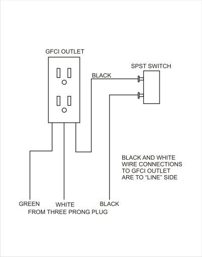
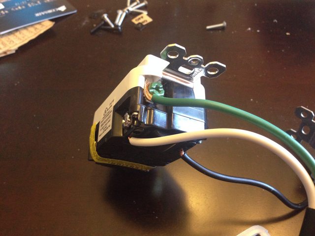
First step is to wire the switch and outlet together:
58LkOpyl.jpg


Then take a good few inches off the end of your workshop replacement cord to expose the three wires (green, white, black). Strip 1/4-1/2" from the end of each of the colored wires. Thread this through your gang box through one of the ports. This is important as all the wiring will be done in the box now.
4e0k84Dl.jpg


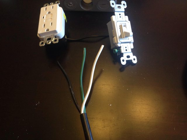
As in the above diagram, green to ground, white to white. Not shown is black to switch.
11sByiBl.jpg


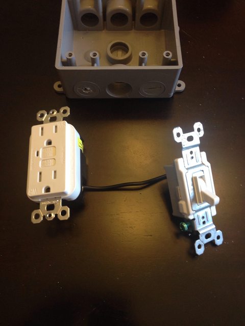
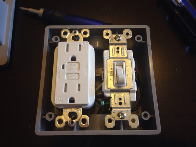
Screw the switch and GFCI outlet ports down in your box:
80vMCSBl.jpg


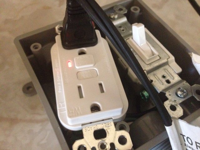
Before bolting everything else together, do a quick test to make sure that everything is working. I plugged in my fermentation heater to do a quick test to make sure everything worked. The switch should turn all power off to the outlets, and then also pressing the test button on the outlet should pop the "reset" button and turn on the indicator light.
wVywms2l.jpg


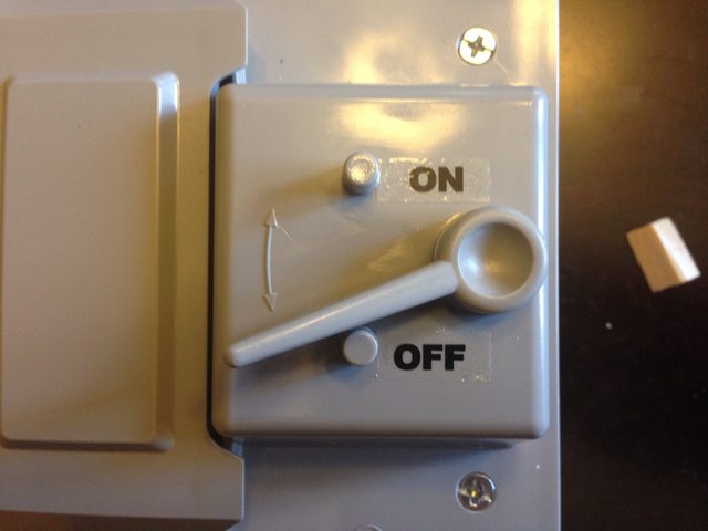
Screw your cover down, making sure the seals are compressed and the outlet is centered in the hole so the cover seals properly. Make sure you take note of what position the switch is in, and what position on and off are.
Jbx2Xkbl.jpg


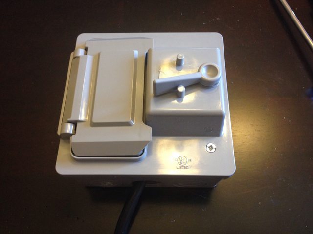
The cover even came with some nice on/off stickers:
ZcLv547l.jpg


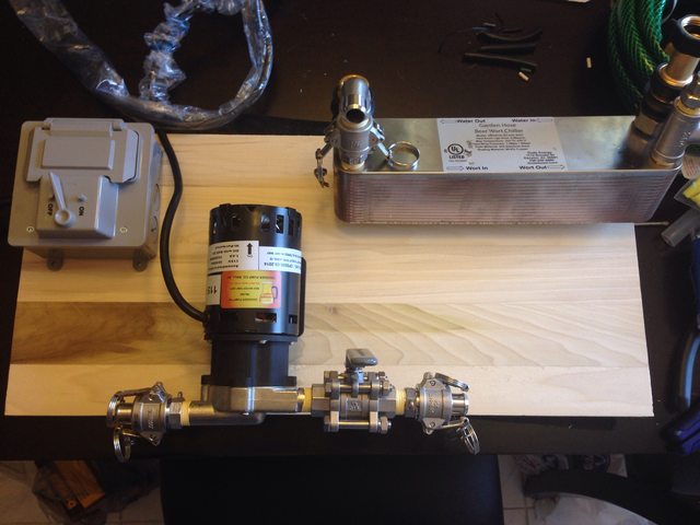
Mount to your brew station/stand/portable setup/etc:
Ek5Vi8Hl.jpg


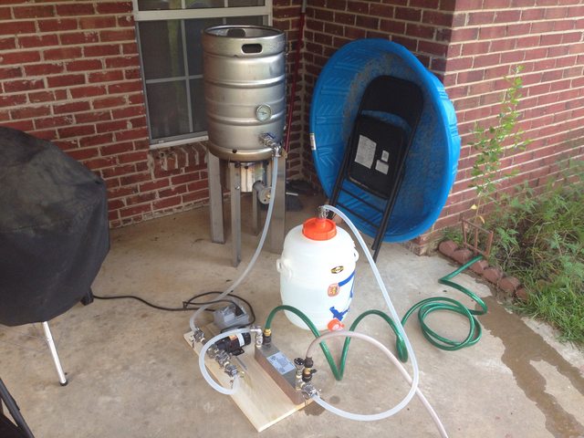
Plug everything in and test for leaks/etc:
FiDj9Mul.jpg


Congrats, you now have a portable GFCI switchbox for your pump setup. Typically outdoor sockets should be GFCI, but this way you can plug into anywhere and know you wont zap yourself if there is a leak.

I'll be ordering a HDPE board to mount this on eventually, as the wood would take a bunch of polyurenthane to seal and prevent water damage. HDPE is easier to maintain in the long run, but more expensive up front.

Hope you enjoyed, and please note I'm not a certified electrician...so do this at your own risk. :mug:
 
Nice diagram. I've been wanting to make one of these but I'm gonna be running 2 pumps. Would I have to make a second box? I wanna be able to control each pump indepentantly without having both of them run at the same time and wanna swith for each pump. My electrical skills suck so I have no idea how to make one box that controls 2 pumps.

It's it possible to have just one gfi, 2 switches and say one swith controls the top outlet and the other switch controls the bottom, sorry for the stupidity but like I said my worst dyi is electricial...lol
 
This is a great idea.
I was thinking if you wanted to keep the Outlet cover closed during operation, you can wire the pump right on to the load side of the GFCI outlet.
That way all electrical connections are covered.
 
Nice diagram. I've been wanting to make one of these but I'm gonna be running 2 pumps. Would I have to make a second box? I wanna be able to control each pump indepentantly without having both of them run at the same time and wanna swith for each pump. My electrical skills suck so I have no idea how to make one box that controls 2 pumps.

It's it possible to have just one gfi, 2 switches and say one swith controls the top outlet and the other switch controls the bottom, sorry for the stupidity but like I said my worst dyi is electricial...lol

GFCI outlets are not quite like a normal outlet in being able to separate the sockets/poles. With a normal plug, you can break the tab that connects them and have the top socket operate separate from a bottom socket. For example, I did this with my two STC-1000's. One socket is for the heater, one socket is for the freezer to run off of.

The only way I can see you being able to have two pumps operate on a GFCI circuit is:

Code:
                             plug w/wire to switch 1 -> pump 1
Wall Power -> GFCI socket -<
                             plug w/wire to switch 2 -> pump 2

This in theory should keep the whole circuit GFCI protected and enable you to power two pumps independently. Someone please correct me if I'm wrong.
 
This is a great idea.
I was thinking if you wanted to keep the Outlet cover closed during operation, you can wire the pump right on to the load side of the GFCI outlet.
That way all electrical connections are covered.

Thanks! My chugger pump came with a three prong cord, so I didn't feel like mangling the end by hard wiring it. I went with a water and tamper resistant GFCI outlet, so I think even if water gets splashed on it, I'll be ok. I mainly wanted a water resistant housing to wire everything in that was also modular and left all components stock. I did something similar with my Keezer where I can go back to completely stock if needed.
 
I went with a water and tamper resistant GFCI outlet, so I think even if water gets splashed on it, I'll be ok. I mainly wanted a water resistant housing to wire everything in that was also modular and left all components stock.

Note that the WR on that receptacle is for Weather Resistant, not Water Resistant. The design requirements for a Weather Resistant receptacle call for materials improvements - not splash resistance. They include corrosion resistant metal parts and UV and temperature resistant plastics.

The manual for that Pass & Seymour receptacle specifically states:
Receptacles still require a weatherproof cover in wet or damp locations.

You should be using a cover that is designed to be splash resistant while in use. Especially when the receptacle is mounted facing up alongside the water connections of your pump.
 
Note that the WR on that receptacle is for Weather Resistant, not Water Resistant. The design requirements for a Weather Resistant receptacle call for materials improvements - not splash resistance. They include corrosion resistant metal parts and UV and temperature resistant plastics.

The manual for that Pass & Seymour receptacle specifically states:


You should be using a cover that is designed to be splash resistant while in use. Especially when the receptacle is mounted facing up alongside the water connections of your pump.

Good eye. I can't believe I misread that when I was purchasing the outlet. I think I'll have to re-think my placement of where I mount the box.
 
Does it matter that I got a 15 amp 14 gauge cord with a 20 amp switch and 20 amp gfci?

Or do I need to get the 15 amp switch and gfci?
 
To expand a bit, folks here sometimes say things like "it will work just fine" when there's still something questionable about the design as it relates to code compliance or potential safety issues. What you have described as far as a 15 amp cord with these 20 amp components really is OK across the board. The reason it's OK is that the pump won't be overloading the lowest rated component, the cord. The switch and receptacle are rated to handle more but that doesn't cause any more current to pass through the circuit.

If you were to plug it into a source receptacle protected by a 20 amp breaker or fuse, AND use this box to control more than 15 amps of loads (like a pump with a heater), then you would want to upgrade the cord to a 20 amp cord. No need to downgrade the switch and receptacle, but potential to need to upgrade the cord in those circumstances.

What I said above applies to this specific set of circumstances. Anyone doing something that's similar but uses different components needs to understand that their situation may have different requirements to be OK.
 
Thanks for posting this again, you made this very simple for a non electrical savvy person like myself..lol

20140703_144521.jpg
 
Thanks for the build and inspiration for my GFCI box! I'll be posting my new brew stand build soon.
 
One trick thing you can do is mount the outlet box to your board sideways, then run a 2 foot length of PVC pipe vertical and mount your switch box to that so you don't have to keep bending over to operate it. It also allows you to use "in use" waterproof covers for the outlets.
 
ImageUploadedByHome Brew1406915728.548292.jpg
I thought about using pipe on mine but used a 2x4 instead.


Sent from my iPhone using Home Brew
 
I just built this today. The gang box cover with the switch would not reach my light switch (which is the same switch in the OP). DId anyone else have a problem with this fitting their switch? Perhaps I just got a bad cover, but I ended up taking it back and getting a drop cover. Since mine will be mounted high enough to be away from any incidental liquid spills, I'm confident that will be just what I need.
 
This is perfect, I just did a brew last night with my pump and plate chiller for the first time and this is exactly what I need. Thanks for sharing.
 
Here is my version of the same basic idea. My March pump is mounted on the burner stand and I also wanted to be able to switch my sump pump. So I ended up with two switched outlets and a total of seven that are not switched counting the hard wired outlet strip under the switches.

There are some mis-matched parts used but all of the electrical hardware, with the exception of the switch cover, are from my spare parts bin. Much of it is previously used.

My "handcart".;

tmp_2014-09-19 08.00.39-1671913565.jpg
 
I'll be ordering a HDPE board to mount this on eventually, as the wood would take a bunch of polyurenthane to seal and prevent water damage. HDPE is easier to maintain in the long run, but more expensive up front.

Probably a little late for this, but Sam's Club has decent sized cutting boards for a reasonable price. I never have priced HDPE as a raw material, but a cutting board may be a cheaper alternative.
 
Bumping this since it's a great instructional thread for someone like me who doesn't know how easy electrical wiring Coe s to people. I will say I had to read the instructions on my GFCI outlet because it comes in a tripped condition and I had to reset it with something plugged in.

Test fit everything with the cover on too. It's easier to build it when you see how everything will work with the cover on. I had to flip my switches after I tested it for functionality.
 
Nice diagram. I've been wanting to make one of these but I'm gonna be running 2 pumps. Would I have to make a second box? I wanna be able to control each pump indepentantly without having both of them run at the same time and wanna swith for each pump. My electrical skills suck so I have no idea how to make one box that controls 2 pumps.

It's it possible to have just one gfi, 2 switches and say one swith controls the top outlet and the other switch controls the bottom, sorry for the stupidity but like I said my worst dyi is electricial...lol

I'm wondering if you ever did this. I'm in the same situation where I'd like my pumps on separate switched outlets.

GFCI outlets are not quite like a normal outlet in being able to separate the sockets/poles. With a normal plug, you can break the tab that connects them and have the top socket operate separate from a bottom socket. For example, I did this with my two STC-1000's. One socket is for the heater, one socket is for the freezer to run off of.

The only way I can see you being able to have two pumps operate on a GFCI circuit is:

Code:
                             plug w/wire to switch 1 -> pump 1
Wall Power -> GFCI socket -<
                             plug w/wire to switch 2 -> pump 2

This in theory should keep the whole circuit GFCI protected and enable you to power two pumps independently. Someone please correct me if I'm wrong.

Any updates or pictures would be great.
 
@Taquina what you're looking for is here. https://www.homebrewtalk.com/showthread.php?t=598063 This might help you.

For the photos, just look at a brand new outlet. On the side you'll see the tab he is talking about. It's just like wiring a half hot but in this case you'd have two switches (one wired to each side of the outlet) and the outlet with both pumps plugged in. Flip the switch controlling the top half of the outlet turns on one pump. Flip the second switch controlling the second outlet and you turn on pump two. You'd probably also need to wire both sides to get power from the Wall Power source because you're breaking the tabs off sending power to both sides. I think the link at the start of my post would be easier but if you don't want to cut off the pump plugs I'd wire up the outlets one at a time and test for power using a volt meter.
 
Back
Top