CraftBeerPi - Raspberry Pi Software

Homebrew Talk - Beer, Wine, Mead, & Cider Brewing Discussion Forum

Help Support Homebrew Talk - Beer, Wine, Mead, & Cider Brewing Discussion Forum:

This site may earn a commission from merchant affiliate links, including eBay, Amazon, and others.
You can easily control the speed of a 12/24V DC pump from a microcontroller output that can drive a high frequency PWM output. All you need is a FET transistor. Use the microcontroller's pin to drive the gate of the FET. I do this with an Arduino. Disclaimer, I haven't done this on a Pi and I have no idea if the craftbeerpi SW will support high frequency PWM outputs.

There Pi only has one PWM capable output, and I don't know how high in frequency it can go. There are PWM output add on boards though.
 
There Pi only has one PWM capable output, and I don't know how high in frequency it can go. There are PWM output add on boards though.

This is a canard. If you use pigpio (for example) you can have very fast PWM on any GPIO pin.

http://abyz.co.uk/rpi/pigpio/
 
This is a canard. If you use pigpio (for example) you can have very fast PWM on any GPIO pin.

http://abyz.co.uk/rpi/pigpio/

Oh, interesting. Strange how the Raspberry Pi specs and tutorials all insist there is only one PWM output.

OTOH, how much CPU resource does running a couple of high-speed PWM pins use at say 1 to 5 kHz cycle times, which is what the DC pumps need (AIUI)?
 
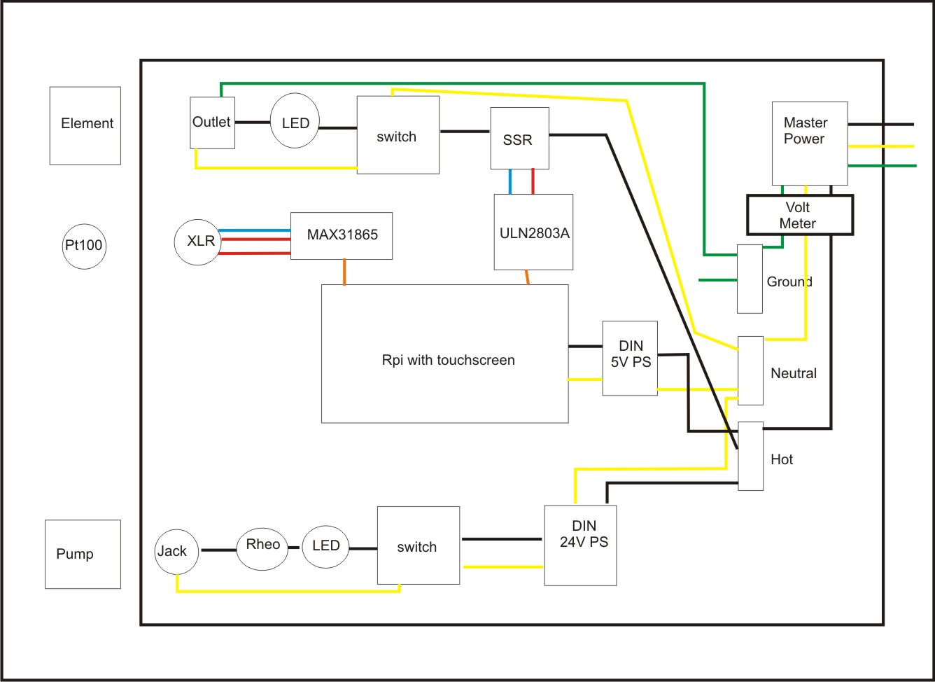
So after much reading and planning, I think I've come up with a controller that will meet my needs. I'm looking to make a 120v BIAB controller for 3 gallon batches. I intend to control the pump flow manually which is why there is a rheostat in the design. There will be a small DIN rail for the two power supplies, and I will ground that to the ground bus. The chassis will also be grounded to the bus. Can someone comment on my schematic? Feel free to propose alternatives... I'm still a noob, albeit with some mechanical aptitude.

controller2.jpg
 
Oh, interesting. Strange how the Raspberry Pi specs and tutorials all insist there is only one PWM output.

OTOH, how much CPU resource does running a couple of high-speed PWM pins use at say 1 to 5 kHz cycle times, which is what the DC pumps need (AIUI)?

Indeed there is only one hardware PWM channel, but clever design means you can have lots of software PWM channels.

CPU load is minimal.
 
So after much reading and planning, I think I've come up with a controller that will meet my needs. I'm looking to make a 120v BIAB controller for 3 gallon batches. I intend to control the pump flow manually which is why there is a rheostat in the design. There will be a small DIN rail for the two power supplies, and I will ground that to the ground bus. The chassis will also be grounded to the bus. Can someone comment on my schematic? Feel free to propose alternatives... I'm still a noob, albeit with some mechanical aptitude.

Don't put your LEDs in series with your load. They should be in parallel with their own neutral for AC or GND for DC.

The outputs of your DC power supplies should be tied to your chassis ground. You should change those from yellow to green for clarification as well.
 
Don't put your LEDs in series with your load. They should be in parallel with their own neutral for AC or GND for DC.

The outputs of your DC power supplies should be tied to your chassis ground. You should change those from yellow to green for clarification as well.

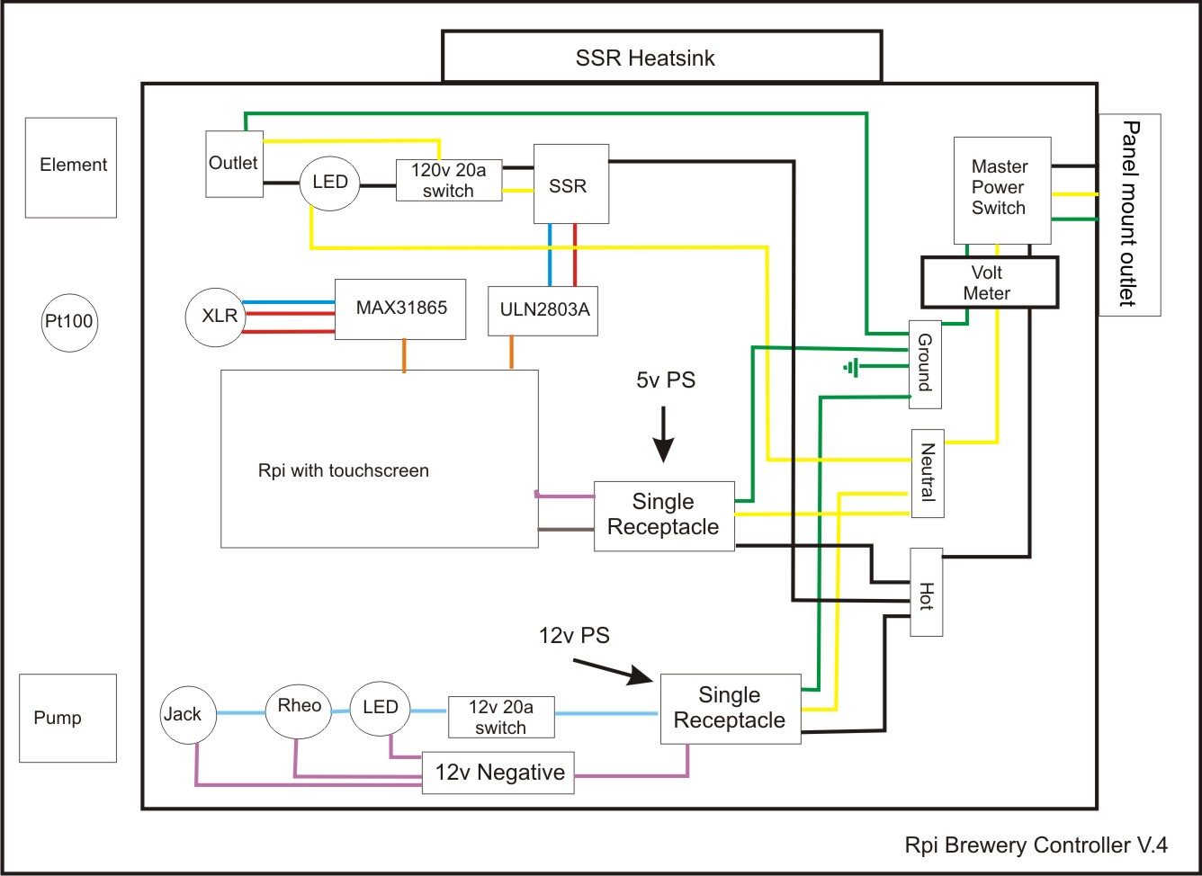
Thanks for the guidance. I think I've come up with something a little cleaner. I have rerouted the neutrals on the LEDs. I've also switched to single receptacles that the two power supplies can be plugged in to. My thoughts are to energize the panel in three phases, master which turns on the Pi, element, and pump. Hopefully this will limit the total inrush current. Does this make sense? I'm also considering some sort of alarm actuated by the RPi. I've attached a revised diagram for those who are interested.

I think that my total amperage will be just around 12 amps if I've counted everything correctly. Element 9.2 Pi 2.4 pump 0.6

I'm still not certain though if I need the negative pathway through the LED and rheostat, of if I can go from the power supply to the jack on the negative side, and wire the LED and rheo in serial on the positive side.

controller4.jpg
 
Perhaps I'm missing the obvious, but where is the "invert GPIO" option in CBP3?????
 
Thanks for the guidance. I think I've come up with something a little cleaner. I have rerouted the neutrals on the LEDs. I've also switched to single receptacles that the two power supplies can be plugged in to. My thoughts are to energize the panel in three phases, master which turns on the Pi, element, and pump. Hopefully this will limit the total inrush current. Does this make sense? I'm also considering some sort of alarm actuated by the RPi. I've attached a revised diagram for those who are interested.

I think that my total amperage will be just around 12 amps if I've counted everything correctly. Element 9.2 Pi 2.4 pump 0.6

I'm still not certain though if I need the negative pathway through the LED and rheostat, of if I can go from the power supply to the jack on the negative side, and wire the LED and rheo in serial on the positive side.

You did not fix the 2 things I mentioned. You should take a look at other wiring diagrams on here to see how to hook up the LEDs.
 
Because I'm scared silly of tinkering with electricity I'm going to go down the USB Plug (Gembird) route

I'm going to use my 15Gal SS Brewtech kettle & false bottom to create a sorta Grainfather, only kickassier.

Just wondering if someone wants to point out some idiocy in the parts list:

Recirc
  • 12v solar pump with 12v adapter €19
  • Something to connect the pump to the 1/2" t piece used for the temo control after the mash tun ball valve €5(?)
  • Female to male hose barb €5(?)
  • Bulkhead for hose return
  • Tubing
  • Ball valve after pump
  • One way valve for after ball valve
Subtotal €40-€50

Temp Sensor
I'm placing it after the ball valve in the kettle so I'll need:
  • 1 x DS18B20 Digital Temperature Sensor G1/2" Thread Probe €10,31
  • 1 x Role of Sealing Tape €2,15
  • 1 x Gembird USB Power Adapter €44,99
  • 1 x T Piece ~€5 in local DIY store
Subtotal ~€62

Raspberry
Subtotal: €57,50


*****************************
Total: ~€170
*****************************

The only downside is I won't get the use of the full 3500W of my induction hob, only 2500W. That should be enough for the mash and I'll just go manual for heating the strike water and boiling. Alternatively, I could have everything set up in the morning and ssh into the cbp and start heating the water an hour before I get home.

Comments, critique, suggestions and abuse all welcome :D
 
Last edited by a moderator:
I think I have this figured out now, or rather I hope I do. I've moved the LEDs so that they're wired more appropriately. My intent was to have the 12v and 5v outlets host wall warts, but I suppose I could use a doorbell transformer for the 12v. I don't know any other way to get the 5v output for the RPi. I could probably control the pump with this speed control?

Another question... If I put in a positive bus on the low voltage side, could I install a case fan?

I've attached the detail drawings of the two redesigned portions.

Element 1.jpg


pump1.jpg
 
Last edited by a moderator:
I think I have this figured out now, or rather I hope I do. I've moved the LEDs so that they're wired more appropriately. My intent was to have the 12v and 5v outlets host wall warts, but I suppose I could use a doorbell transformer for the 12v. I don't know any other way to get the 5v output for the RPi. I could probably control the pump with this speed control?

Another question... If I put in a positive bus on the low voltage side, could I install a case fan?

I've attached the detail drawings of the two redesigned portions.

The LEDs look better now, but you should still tie the negative output of your DC power supplies to chassis ground.

Transformers only work with AC current. You need a DC supply for a DC pump. You would need to add a bridge rectifier as well as capacitors behind the transformer to convert it from AC to DC. Your better off using a 12V DC power supply instead of messing with that, given that you are new to electronics.

You can easily add a 12V DC fan in parallel to your other loads of your 12V DC power supply. Not sure what you mean by adding a positive bus, you already have one. That's how your pump is powered.

The speed controller you linked should work. Most DC pumps are only an amp or 2.
 
Last edited by a moderator:
Transformers only work with AC current. You need a DC supply for a DC pump. You would need to add a bridge rectifier as well as capacitors behind the transformer to convert it from AC to DC. Your better off using a 12V DC power supply instead of messing with that, given that you are new to electronics.

You can easily add a 12V DC fan in parallel to your other loads of your 12V DC power supply. Not sure what you mean by adding a positive bus, you already have one. That's how your pump is powered.

The speed controller you linked should work. Most DC pumps are only an amp or 2.

If he uses the terragady board (maybe the official CraftBeerPi board as well?) for breaking out the Pi outputs, that also includes a 12v-5v voltage regulator, so that the Pi will be powered off the same 12v. A simple 12v switch mode supply with may 5-7A output current will happily run the pumps and the Pi.

Note that the Pi can be sensitive to power supply issues, so using a well designed PSU is a good idea.
 
The LEDs look better now, but you should still tie the negative output of your DC power supplies to chassis ground.

I'm not sure what you mean exactly. I intend to use standard wall warts plugged into the two receptacles. That should make them grounded, as the receptacles are grounded, no?
 
If he uses the terragady board (maybe the official CraftBeerPi board as well?) for breaking out the Pi outputs, that also includes a 12v-5v voltage regulator, so that the Pi will be powered off the same 12v. A simple 12v switch mode supply with may 5-7A output current will happily run the pumps and the Pi.

Note that the Pi can be sensitive to power supply issues, so using a well designed PSU is a good idea.

Correct about the official board. It has a Buck module and will happily power the Pi and send 12v to the outputs.
 
I'm not sure what you mean exactly. I intend to use standard wall warts plugged into the two receptacles. That should make them grounded, as the receptacles are grounded, no?

Most of them have isolated outputs, meaning that the negative side is floating and not connected to ground. Floating grounds can cause problems, and can be difficult to diagnose.
 
Most of them have isolated outputs, meaning that the negative side is floating and not connected to ground. Floating grounds can cause problems, and can be difficult to diagnose.

Ah, gotcha. So if I run a line back from my 12v negative to my 120v ground I should be OK?
 
OK, so I cleaned things up a bit by removing the 12v circuit. I will control the pump manually via the ball valve. I still have to figure out how to control the Pi, perhaps something like this 5v power supply?

Anyhow, here's the new version:

120v Control2.jpg
 
OK, so I cleaned things up a bit by removing the 12v circuit. I will control the pump manually via the ball valve. I still have to figure out how to control the Pi, perhaps something like this 5v power supply?

Anyhow, here's the new version:

The new revision of CBPi has pump control built in.
 
So how would I wire that up then? My pump is going to be one of the 12v/24v solar water pumps, rather than a March pump.

Pretty sure you just wire just as it's shown on the CBPi diagram at their site, the controller takes care of the rest. You'll just need a DC-DC SSR
 
So how would I wire that up then? My pump is going to be one of the 12v/24v solar water pumps, rather than a March pump.


There are a few different ways to accomplish this. If you can solder your own components onto a board I can walk you through how to build one, if you're looking for just fast and easy the official board and a 12v power supply will do it depending on the amperage draw of the pump. If the pump pulls to many amps you can either use a switching circuit with a mosfet or a dc-dc solid state relay. If you want help pm me and I'll do my best to walk you through it.

http://www.electronics-tutorials.ws/transistor/tran_7.html

http://m.ebay.com/itm/Universal-12V...a821a381ffff246b%7Ciid%3A1&varId=460322536102

https://www.powr.io/plugins/form-builder/view/8315797?mode=page
 
Hi all - I'm a functional computer illiterate so bear with me. I just downloaded CBP 3.0 but I can't figure out how to make it so that 2.2 does not start when you go to the web address. I understand how to disable auto start for 2.2 but can't get 3.0 to auto start. Any ideas?
 
Hi all - I'm a functional computer illiterate so bear with me. I just downloaded CBP 3.0 but I can't figure out how to make it so that 2.2 does not start when you go to the web address. I understand how to disable auto start for 2.2 but can't get 3.0 to auto start. Any ideas?

Quoting another user from the Facebook group...

Question said:
hi all - just installed 3.0 into my hosehead. How do I set it to autostart instead of it starting in 2.2?

Answer said:
Easiest way.

Run run.py and do "Remove Autostart" then " Add autostart"

I did
Before install of 3
sudo update-rc.d -f craftbeerpiboot remove
sudo mv craftbeerpiboot craftbeerpiboot2
Then editors craftbeerpiboot2 to give it a different daemon name etc. now I can still start and stop craftbeerpiboot2 if I need for testing.

Then installed 3.
 
easiest way is to do fresh install like if you use noobs you have recovery partition where you can go back to "factory image" and install CBPi from scratch with needed libraries.
 
Hey Guys and Gals looking for some help. I recently blew my PID controllers in a very long story.

What I currently have:

1x240V circuit input

1x240v output (for 5500w element)
2x120v outputs (one for pump and one for 120v recirculating element)

I have (2) 240v contactors (120v coils) for the elements

The PIDs I had were the auberins EZ Boils [because of the humidity in the room from the boil it shorted out my contactors and PIDs making them no longer functional.

I bought new contactors but instead of buying new PIDs I have a raspberry pi and an arduino mega sitting at the house and figured I could replace the PIDs with either one of them or both if it comes to it. I already have (2) MAX31865s at the house, (2) PT100 3 wire temps sensors, and (2) SSRs.

My questions is how can I make this all work together? Anyone have wiring diagrams, source code, etc that I could use to make this work?
 
Not sure, but if it's too humid for PIDs, i don't think a raspberry pi or arduino board will fair any better
 
^That^ is true. I've designed literally hundreds of PCBs over 44 years and every one of them shipped/ships with specifications that clearly spell out "Non-Condensing" wrt allowable operating humidity...

Cheers!
 
Trying to do a fresh install of 3.0. Got thru the install and try to start from install screen but it tells me to start from chromium. When I put in my ip address:5000, it says it cant access it. When I do a reboot the CBP logo flashes full screen for a second, then goes to normal Raspberry home screen. What have I done wrong and how to fix it?
 
Well after deleting and reinstalling 3 times, it decided to work. This is too much like being the only guy a work that knows how to turn on the computers, lol

Hey Neighbor.

If you have a KB, Mouse and monitor connected to the Pi, you should just be able to go to http://localhost:5000

I recently installed 3.0 and have been testing it to see if it's something I want to use for brewing, it fired up OK ...MUCH more straightforward compared to the SB Elsinore in my experience.

Howdy!

I had 2.* version before and it worked good. Much better than Strange Brew. I got the 3.0 running but have not brewed with it yet. But it feels smoother. I think it will work better with my BeerSmith files
 
Hey Guys and Gals looking for some help. I recently blew my PID controllers in a very long story.

What I currently have:

1x240V circuit input

1x240v output (for 5500w element)
2x120v outputs (one for pump and one for 120v recirculating element)

I have (2) 240v contactors (120v coils) for the elements

The PIDs I had were the auberins EZ Boils [because of the humidity in the room from the boil it shorted out my contactors and PIDs making them no longer functional.

I bought new contactors but instead of buying new PIDs I have a raspberry pi and an arduino mega sitting at the house and figured I could replace the PIDs with either one of them or both if it comes to it. I already have (2) MAX31865s at the house, (2) PT100 3 wire temps sensors, and (2) SSRs.

My questions is how can I make this all work together? Anyone have wiring diagrams, source code, etc that I could use to make this work?


It sounds like you need a fully sealed enclosure not new electronics. You can also get mini dehumidifiers for electronics enclosures, but they are way more expensive than sealing everything up.
 
Howdy!

I had 2.* version before and it worked good. Much better than Strange Brew. I got the 3.0 running but have not brewed with it yet. But it feels smoother. I think it will work better with my BeerSmith files

Well, I guess my dumb is showing again- can't find a way to import files in 3.0. Also had to reinstall a few times again to get the auto off/on to work.

I am spending more time play with computers than brewing beer :confused:
 
i have connect everything.....i have installed cbpi 2.2 on by the book successfully ssr seems to be open (led light on) with manual action from the Gui but no power on outlet... any suggestion? ????
 
Check the voltage and that it is connected correctly plus to plus, etc.. are you using the shield or direct to the gpio? What's your power supply voltage and amperage?
 
Well, I guess my dumb is showing again- can't find a way to import files in 3.0. Also had to reinstall a few times again to get the auto off/on to work.

I am spending more time play with computers than brewing beer :confused:

To import, click the steps icon, then on the left side, there's an import link, click that. It should ask you to import a file. My pi is disconnected so I can't check actual verbiage, but this should get you to the correct screen.
 
Back
Top