• Please visit and share your knowledge at our sister communities:
  • If you have not, please join our official Homebrewing Facebook Group!

    Homebrewing Facebook Group

3-wire -> Spa GFI -> Control box

Homebrew Talk

Help Support Homebrew Talk:

This site may earn a commission from merchant affiliate links, including eBay, Amazon, and others.

Howhownow

Well-Known Member
Joined
Apr 15, 2014
Messages
391
Reaction score
71
Location
Chapel Hill
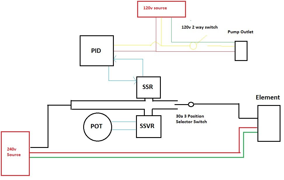
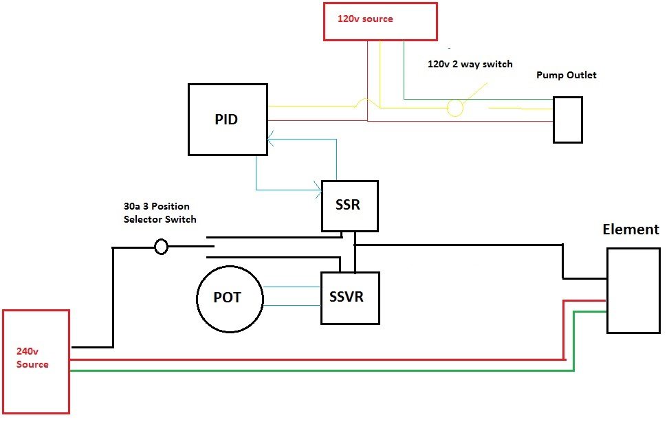
Ok, so I have been doing quite a bit of reading and learning as I build my 240v electric system and evaluate my current situation and control box options.

I have seen many versions of this question asked many different ways... but I still can't find a satisfactory answer and explanation that fits my specific situation (though mine seems like it should be pretty common). I'll try to be as simple in my explanation as I can. I have a basic electrical understanding, but am by no means an expert.

I would like to draw power from my old dryer plug that has a NEMA 10-30 receptacle, 3 wire config back to breaker box. The non-hot leg runs to what I believe is the grounding bus (bare copper coming back from other circuits). Trying to avoid running new lines to/ replacing the plug for complicated reasons.

My plan was to go from this plug to a Spa box GFCI, hard wire that to a control box(make/model TBD, but I plan to buy one off the shelf), and use that to power a 5500w element, pump, and whatever electric components in the box. The Spa box I purchased has clear directions for both 3-wire and 4-wire input configurations.

Many control box makers state that their units will not work with GFCI protection if the power source (to GFCI breaker) is 3-wire. This throws off my whole plan (and I would imagine the plans of anyone trying to use a dryer outlet and a control box yet not be electrocuted).

My question is- for what reason does the 3-wire config not work with a Spa box and control panel?

A) Does it have to do with the fact that the control box components (PID, lights, pump power) 'borrows' from one of the hot legs, causing an unbalanced return and nuisance trips on the GFCI? Would a controller using a second 120v input (such as the brew-boss) remedy this by dedicating the 240 circuit to the element?

B) It has nothing to do with controllers, Spa box GFCIs just don't work with 3-wire configs. (If this is the case, I am struggling with the reason why. This is my electrical inexperience).

C) Does it not work for another reason having to do with the way GFCIs work that I'm not aware of. If so... please explain plainly.

D) WTF am I talking about??
 
First of all, IANAE, at all, so grains of salt abound.

If I understand your question correctly, I think the issue is A) -- many control boxes use a 120 circuit formed by the neutral and one of the hot legs. In that situation, there shouldn't be any reason why a controller with a separate 120V input like the Brew-Boss or Hosehead shouldn't work.
 
So, stated a bit differently, it's not the nature of the GFCI that creates the issue?

Asked differently again: If I ran a 3-wire -> Spa box-> straight to a element with no control box or other equipment in between, there would not be a problem?
 
For GFCI to work you need a hot leg and a netural (not ground). To be safe you need a ground too. For 240V that means two hots (red and black), a neutral (white), and a ground (green).

You can wire a GFCI breaker to your 3 wire dryer outlet but you will not have a ground. The breaker will still trip if any current goes where it's not supposed to - like through you. The risk is that without a ground you are more likely to be shocked if something breaks.

Personally, I would not do it.
 
gfi needs 4 wire for it to work it trips when there is a difference between neutral and ground
there are inline gfi but they are expensive
you can run on 3 wire and have 120v or 240v you just won't have gfi

look at jaggerbushbrewing.com and there pinterest page for more info
 
For GFCI to work you need a hot leg and a netural (not ground). To be safe you need a ground too. For 240V that means two hots (red and black), a neutral (white), and a ground (green).

You can wire a GFCI breaker to your 3 wire dryer outlet but you will not have a ground. The breaker will still trip if any current goes where it's not supposed to - like through you. The risk is that without a ground you are more likely to be shocked if something breaks.

Personally, I would not do it.

An example will help clarify this:

In a GFCI with ground system you have both red and black wires running to the kettle element with a green ground. If any current leaves the red or black wires it will go into the ground and the GFCI will trip.

In a GFCI setup without ground you will still have red and black going to the element but will have a white neutral wire in place of the ground. If any current leaves the red or black wires it will return on the white wire and the GFCI will not trip. As soon as you touch the kettle and get shocked some current flows into you and the breaker trips.
 
GFI's do not require a neutral or a ground to function. They measure current imbalance and trip when it exceeds some tiny threshold. For US 120 V circuits, that is the difference between the hot and neutral. For US 240 V circuits, it can be the difference between the two hots (line 1 and line 2) OR the sum difference between line 1, line 2, and neutral.

If the power supply to your GFI spa panel is 3 wire (two hots and a ground) then the output from the GFI to your control panel can only be 3 wire. I haven't looked at many off the shelf control panels to see if there are any that take 3 wire 240 V service in. If you wanted to build your own, you can source 240 V components like LEDs, switches, PID controllers, etc. If you want to add in pump control, you would most likely need 240 V pumps which I believe are uncommon. I don't know enough to say you can convert your 240 V in to 12/24 V DC to use those cheap tan pumps w/o requiring a neutral.

Link to a presentation that outlines GFI basics.

Asked differently again: If I ran a 3-wire -> Spa box-> straight to a element with no control box or other equipment in between, there would not be a problem?

Correct as far as a completed and safe circuit is concerned. You obviously would not have any control over the heating element other than on/off.
 
It seems crazy that no one is running a GFCI protected 3-wire control box. It seems like so many electric builds here start with "so I have this old dryer outlet...".
One additional question- what if I, instead of the spa box , installed a GFCI breaker in the box itself? I know they're more expensive... but they're cheaper than a trip from the electrician (who, despite my stubbornness, it is seeming more and more like I am going to need to call. I like solving problems myself...but I like not being electrocuted more).
 
GFI's do not require a neutral or a ground to function. They measure current imbalance and trip when it exceeds some tiny threshold. For US 120 V circuits, that is the difference between the hot and neutral. For US 240 V circuits, it can be the difference between the two hots (line 1 and line 2) OR the sum difference between line 1, line 2, and neutral.

Link to a presentation that outlines GFI basics.

Correct as far as a completed and safe circuit is concerned. You obviously would not have any control over the heating element other than on/off.

Thanks WI_Wino. I had seen that or a similar presentation, leading me to my original conclusion A.
Yeah the situation outlined was for example only. Not how I'm actually looking to set it up.

Well, now feeling even more conflicted/ confused.
 
It seems crazy that no one is running a GFCI protected 3-wire control box. It seems like so many electric builds here start with "so I have this old dryer outlet...".
One additional question- what if I, instead of the spa box , installed a GFCI breaker in the box itself? I know they're more expensive... but they're cheaper than a trip from the electrician (who, despite my stubbornness, it is seeming more and more like I am going to need to call. I like solving problems myself...but I like not being electrocuted more).

That would be fine for GFI protection but you still have the lack of a neutral at your outlet to contend with. Since your dryer outlet is most likely a home run back to the main breaker panel where neutral and ground are bonded, you probably *could* get away with an off the shelf 4 wire 240 V control panel. You would need to make a short adapter cord that takes the 4 wires in from the control panel and leads out to 3 wires where neutral and ground are tied together. I am NOT recommending this though.
 
power-panel-6.jpg
 
It seems crazy that no one is running a GFCI protected 3-wire control box. It seems like so many electric builds here start with "so I have this old dryer outlet...".
One additional question- what if I, instead of the spa box , installed a GFCI breaker in the box itself? I know they're more expensive... but they're cheaper than a trip from the electrician (who, despite my stubbornness, it is seeming more and more like I am going to need to call. I like solving problems myself...but I like not being electrocuted more).
I'm running off my 3 wire dryer outlet going to a spa panel.From there it goes to an extension cord that runs to my control panel.I tested the GFCI by tripping the E stop on the panel and it tripped.Im over a year in with my setup and many 10 gallon batches with no issue.I recommend building a box,I could help if you did the same controller as mine.It will take you at most a day to build everything.This wire goes here,that wire goes there.Not hard and I'm not an electrician.
 
I'm running off my 3 wire dryer outlet going to a spa panel.From there it goes to an extension cord that runs to my control panel.I tested the GFCI by tripping the E stop on the panel and it tripped.Im over a year in with my setup and many 10 gallon batches with no issue.I recommend building a box,I could help if you did the same controller as mine.It will take you at most a day to build everything.This wire goes here,that wire goes there.Not hard and I'm not an electrician.

I really appreciate the offer to help with a controller. I built my old 120v panel- looking to buy off the shelf to save time this go round because there are about 10,000 other projects to work on for the brewery and the 80 years old new (to me) house.

Is your panel PID controlled, and does it have outlet for a pump/whatever 120v accessory? If so, do you "borrow" from one of the lines to power them? Do you ever get any nuisance trips that don't involve, you know, you getting electrocuted?

How did you wire your Spa box?
 
BigFloppy and WI_Wino
I've seen this diagram before- I'm not sure where it gets me. A lot of the off the shelf control boxes are compatible with 3-wire inputs, they just note that this will not be able to use GFCI. Here is the High Gravity controller I was looking at, for reference http://www.highgravitybrew.com/stor...-power-control-p3986.htm?atc=1&idproduct=3986. If I follow this diagram and end up with a 4-wire output, does this solve my issue?

Yes. With the big caveat that you have neutral and ground bonded in your spa panel. That is not to code as I understand it.
 
I really appreciate the offer to help with a controller. I built my old 120v panel- looking to buy off the shelf to save time this go round because there are about 10,000 other projects to work on for the brewery and the 80 years old new (to me) house.

Is your panel PID controlled, and does it have outlet for a pump/whatever 120v accessory? If so, do you "borrow" from one of the lines to power them? Do you ever get any nuisance trips that don't involve, you know, you getting electrocuted?

How did you wire your Spa box?
Yes PID,no outlet for pump,never had a trip of any kind.Im most positive others have borrowed a leg but double check that. I built a very simple controller.I don't need a pump,I have a spoon.I don't need a valve I have an auto siphon. I'm a believer of KISS.
 
You can get by with H/H/G and have GFCI function properly as long as you don't have any 120V loads (pumps, controllers etc.). It is easy enough to get 240 V controllers and pumps of course but there is another option and that is to install a 240V to 120V transformer in/at/near your system. You may tie one leg of the 120V secondary to the safety ground (bare, green...) wire and that leg becomes your 120V neutral. The other is your 120V hot. This is legit because the secondary of the transformer is a 'separately derived system'.
 
Ok, so after much searching, researching, hand wringing, etc., etc., I have decided It may make the most sense for me to just build the damn thing if I'm going to be so picky on specs. The goal is safe, simple. In that order.
My plan B until now was going to be to build a simple 240v rheostat/ SSVR controlled manual boil controller (I already have the parts) and run that through the spa panel. I'd also run my old 120v control box and RIMS tube for the mash. Though this would certainly work, it was causing me a lot of heartburn because it goes directly against the simplicity I am trying to achieve in my brewing (3-vessel to BIAB. Cutting down on all possible "moving parts").
The question kept nagging at me- I have easy access to 3-wire 240v and regular 120v. Can I build a GFCI compliant PID (plus manual) controlled system if I use both?
I am no electrician, as is readily evidenced by this whole thread. That said, I feel that I have a decent layman's grasp, and I've recently been studying this particular problem a lot.
Anyway, requirements:
- Switchable PID/Manual control that will not trip 240v GFCI
Nice to have:
- Pump control

Here is what I came up with (keep in mind that this is the first wiring diagram I've ever attempted). I need feedback on:
A) Does this work, conceptually? Can I have a separate 120v circuit that can power the PID, accessory outlet?
B) If the idea does fly, would I locate the switch before or after the SSR & SSVR?
Note: I used 3-way selector in drawings for simplicity. It would read "Mash (PID) - OFF - BOIL (manual)". It may be a better (and cheaper) to do a regular 2 pole 'Master element off/on' followed by a 3 pole 'Mash - Boil' selection switch.
Note II: not sure if ground and/or second hot leg would need to run through switch, but that us easy to do. I do thing pot needs to be grounded, excluded for simplicity.
C) Would this be a suitable selector switch?

Thin lines are 120v lines, thick 240v.


You can have your PID powered from a different source than the power driving your SSR/SSVR. But most PIDs I have seen work on any voltage from 90V to 240 V. Inside the PID there are circuits designed to take that voltage input range and convert it to whatever the PID needs. So you can tap off of your 240 V that feeds your SSR/SSVR and have that power the PID.

From what I have seen, most panel mount switches are rated for 10 A or less. I don't see a rating on the one you have linked so I personally would not use that switch in this context. You can use it to drive a contactor though and they make contactors where the coil voltage is 240V. You would need to wire it such that switch position 1 completes the circuit for the SSR contactor coil and switch position 3 completes the circuit for the SSVR contactor coil. The Electric Brewery has a page on adapting his panel configuration to an all 240V setup.

I would probably put the switch/contactors before the SSR and SSVR myself but I don't think it makes a difference.

Also you have no GFI in your diagram. Are you going to have the 120 V source and 240 V source protected by independent GFIs?
 

You can definitely make it work with this GFCI configuration. This has been beaten to death, but it is not up to code (neutral and ground should only be bonded in the main panel), so you should make it pluggable rather than permanently wire it. It works, however, and gets you GFCI protection and the ability to have both 120v and 240v circuits in the 4-wire control panel.

You can search this forum for more pro/con discussion, but a reasonable solution IMO, although inferior to a 4 wire run from the main panel.
 
A) Does this work, conceptually? Can I have a separate 120v circuit that can power the PID, accessory outlet?
B) If the idea does fly, would I locate the switch before or after the SSR & SSVR?
Note: I used 3-way selector in drawings for simplicity. It would read "Mash (PID) - OFF - BOIL (manual)". It may be a better (and cheaper) to do a regular 2 pole 'Master element off/on' followed by a 3 pole 'Mash - Boil' selection switch.
Note II: not sure if ground and/or second hot leg would need to run through switch, but that us easy to do. I do thing pot needs to be grounded, excluded for simplicity.
C) Would this be a suitable selector switch?

A. Separate 120 is fine.
B and C. I second the recommendation for a contactor/relay instead of a switch. I would place it before the SSR too. That way you don't have voltage on the SSR all the time, it will only be there when you want to fire the element. I'm not sure if that will affect the SSR's life but it can't hurt.
 
An example will help clarify this:

In a GFCI with ground system you have both red and black wires running to the kettle element with a green ground. If any current leaves the red or black wires it will go into the ground and the GFCI will trip.

In a GFCI setup without ground you will still have red and black going to the element but will have a white neutral wire in place of the ground. If any current leaves the red or black wires it will return on the white wire and the GFCI will not trip. As soon as you touch the kettle and get shocked some current flows into you and the breaker trips.
A GFCI does not trip because current is flowing to ground. In fact, ground current isn't even usually monitored. A GFCI monitors current flow in the normal current carrying conductors of a circuit and trips when they are unequal.

For a 240v circuit: If the current in the red and black wires are unequal, a correctly wired and functional GFCI, WILL trip. This is independent of the neutral current. The reason the neutral must be routed through the GFCI breaker is to monitor the 120v circuit.

As the diagrams posted indicate, both a fully functional neutral and ground are created with a 3wire to 4 wire spa panel configuration. As stated, hard wiring it will be against code, which doesn't allow neutral and ground to be attached to the same bus except in the main panel. BTW, it is very important that the neutral/ground connection at the main panel be verified.
 
Is there no way of running a new wire? You could, so it won't be as expensive and will be easier to run, get a spool of insulated grounding wire (like this: http://www.amazon.com/dp/B008OILG5I/?tag=skimlinks_replacement-20) and add the ground going to the panel instead of replacing the entire 3 wire you have now with 4 wire.

My issue with my wiring is that my main boxand the conduit line with 240 service are all on a basement wall that is otherwise covered with a moisture barrier that I don't want to penetrate with any new holes, especially ones involving electricity. Don't want to remove any existing conduit, and the 10-30 plug is mounted to the wall and I don't know what's underneath it. Whatever is already there works (no moisture penetration), and I just don't want to mess with it.
Won't talk any more about that because it really freaks me out, but that's my reason for keeping what I have.
I suppose I could conceivably still run a ground wire externally to the conduit... I just see this as a last(ish) option.
 
Last edited by a moderator:
You can have your PID powered from a different source than the power driving your SSR/SSVR. But most PIDs I have seen work on any voltage from 90V to 240 V. Inside the PID there are circuits designed to take that voltage input range and convert it to whatever the PID needs. So you can tap off of your 240 V that feeds your SSR/SSVR and have that power the PID.

From what I have seen, most panel mount switches are rated for 10 A or less. I don't see a rating on the one you have linked so I personally would not use that switch in this context. You can use it to drive a contactor though and they make contactors where the coil voltage is 240V. You would need to wire it such that switch position 1 completes the circuit for the SSR contactor coil and switch position 3 completes the circuit for the SSVR contactor coil. The Electric Brewery has a page on adapting his panel configuration to an all 240V setup.

I would probably put the switch/contactors before the SSR and SSVR myself but I don't think it makes a difference.

Also you have no GFI in your diagram. Are you going to have the 120 V source and 240 V source protected by independent GFIs?

The Spa Panel is wired up before this diagram starts, will likely hard wire it in.
If I ran the PID off of the power from one of the 120v legs, would that not cause them to be imbalanced and the GFCI to trip (feel like I'm back where I started)?

I would like to avoid contactors just for space. I swear that I was a 30a listing on that switch yesterday... Anyway I was thinking a series of regular toggle switches may do a better job, anyway. First single pole for master element on/off, followed by a 3 pole selecting mash/boil.

Something like this might work, pricey though:
http://www.newark.com/nkk-switches/s823/switch-toggle-dpdt-30a-250vac/dp/10X9544

You don't need a neutral for 240V, you would run line 1 and line 2 to the PID controller. No current imbalance with this. Remember the two hots are out of phase, so the voltage drop across them is 240V. Each one compared to earth/ground is only 120V.
 
OK, so here is a switch that would work better (though not as sexy looking)
http://www.globalindustrial.com/p/e...ouble-Pole-Double-Throw-30A-120-277V-AC-Brown

On the other hand- the contactor route would require two of them, correct?

@raouliii what exactly do you mean about verifying the neutral/ground at the main panel? I have followed the (what are we calling it? 3rd? non-hot?) leg back to what looks like the grounding bar

Yes you would need a contactor for the SSR and one for the SSVR.
 
One other option I just thought of- what if I just used a regular 120v 3-pole toggle (or better, 3-way selector) switch wired to the control wires of both the SSVR and SSR? That in conjunction with a 30A single pole master on-off on the hot being controlled would do the job, right?

There is something that inherently freaks me out about the current still flowing into the SSVR/ SSR and being stopped by just the control wires. If the master on/off is used correctly, the worst case would be what... SSR and SSVR both having control current and PID output being regulated by the pot output? Is that how that would work?

I am not too concerned with impact on SSR/SSVR life span (unless the impact is going to be significant).
 
A GFCI monitors current flow in the normal current carrying conductors of a circuit and trips when they are unequal.

That's close but a GFCI trips when the sum of the currents on the wires through the doughnut is other than 0 (by a threshold amount). Thus in a single phase circuit any current that is launched from the hot (black) that does not return through the neutral (white) is returning some other way which could be the safety ground wire or another path (e.g. through a person who has touched something he shouldn't and it trips. In a 240 volt system any current sourd by the red wire must return through the black wire. If it didn't then there is a potentila hazard and a trip. In a 120/N/120 circuit current sourced by either or the hots (red or b lack) that does not return through the other hot or through the neutral must be returning through another path (such as a person) and the breaker trips. In a Y-connected 3ø system current sourced by any of the phases that does not return through one of the other phases or the neutral is a potential hazard and we have a trip in that situation too.

To summarize, you put all the allowed current carrying conductors (2, 3 or 4) through the doughnut. Any current from any of the allowed conductors that returns through a disallowed conductor results in a non zero sum in the allowed conductors and causs a trip.

For a 240v circuit: If the current in the red and black wires are unequal, a correctly wired and functional GFCI, WILL trip. This is independent of the neutral current. The reason the neutral must be routed through the GFCI breaker is to monitor the 120v circuit.
Not sure exactly what you are trying to say here but in the 120/N/120 circuit a properly wired GFI with unequal currents in the red and black will NOT trip as long as the imbalance current flows through the neutral. That's what it is there for.
 

Latest posts

Back
Top