TeensyPi Networked Temperature Controller

Homebrew Talk - Beer, Wine, Mead, & Cider Brewing Discussion Forum

Help Support Homebrew Talk - Beer, Wine, Mead, & Cider Brewing Discussion Forum:

This site may earn a commission from merchant affiliate links, including eBay, Amazon, and others.
Flushing out all possibilites here...

Have you tried each chip by itself?

Is the mini-lan in non-parasitic mode? In other words is each chip's data pin connected to 3v3 through the 4k7 resistor?

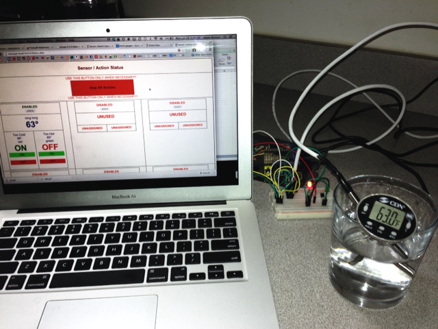
You mentioned that the chips were breadboarded. I've found that sometimes the low-insertion force breadboards get loose after a lot of use and cause unstable connections. The addresses are only collected once, but the status of the chips are collected about every 200ms. Have you tried different positions on the breadboard?
 
connected each one individually to the terminals on the protoboard, 1 read 255, the others read 70, but when I applied cool/heat nothing changed.

going to reload all the software and check the connections again.
 
Currently reloading TeensyPi on the RasPi... will report if that changes anything
 
Got everything reloaded, and connected a sensor directly to the terminals again... worked as expected

muF2oq2.png
 
Just as a test, I added 5 more temp probes and 4 more switches, for a total of 33 devices and it all came right up.

I'm still thinking either a faulty device or bad connection.
 
I'm not sure what ended up being the problem, but after I reloaded all the software (on the RaspPi and Teensy) it works perfectly again.

I may have messed something up loading some other programs, but all good now.

Thanks for your help.

Next up I am going to test my switches and actions.
 
I'm not sure what ended up being the problem, but after I reloaded all the software (on the RaspPi and Teensy) it works perfectly again.

I may have messed something up loading some other programs, but all good now.

Thanks for your help.

Next up I am going to test my switches and actions.

Glad to hear it. Keep me informed :rockin:
 
OK, got the code and database structures in place to assign up to 8 4x20 HD44780-compatible LCDs to the actions.

The I2C interface board that I created uses a MCP23017 16 bit port expander to control the LCD and can also drive either the RGB inputs for the Adafruit RGB displays or the standard 16 pin and an RGB led. The code I wrote for the RPi uses the adafruit python library.

I'll probably release the code sometime this week, after some more testing.
 
Can't get my wifi to work with your image. I use the Adafruit OurLink dongle. It's showing up as wlan1 but won't take an address and I can't tell if the driver is loading with lsmod (no realtek). The LEDs on the dongle are not doing anything either. My SSID is not hidden.

What was the base image you used to build on? Maybe I just need to start there and add the appropriate applications.

I used the Moebius image as my base.
 
I've followed along with the TeensyPi build and have built my TeensyPi. I can get it to boot up and get an ip address, but when I browse to the website I get two errors in quick succession. First I get " unable to select database, then "socket_connect() failed. Reason :() No such file or directory."

I've tried reloading the teensy bits and also loaded a new image on SD card to no avail. Has anybody ran into this?

thnx for any help.

DB error.jpg


socket fail.jpg
 
Got the actions to work as well...
KCJovrS.jpg


Set the "Too Cold" to light the Red LED under 66 and the Green LED over 69.

Sensor also reading accurately, 63.

Have you thought about using the Arduino PID library for the action as opposed to the min/max limits? Therefor it will tune closer to the set temperatures? Or are you using the actions more as alarms currently?

I am going to play around this week, now that I have the basic setup working. I will report my results.
 
I've followed along with the TeensyPi build and have built my TeensyPi. I can get it to boot up and get an ip address, but when I browse to the website I get two errors in quick succession. First I get " unable to select database, then "socket_connect() failed. Reason :() No such file or directory."

I've tried reloading the teensy bits and also loaded a new image on SD card to no avail. Has anybody ran into this?

thnx for any help.

I don't see the socket warnings but I get the same DB error.

EDIT: As I try to troubleshoot this I found I could not log into phpmyadmin so I changed the conf file to allow no password login. Now when I log in I get "Cannot log into the MySQL server"
"Connection for controluser as defined in your configuration failed"

This happens using users "root" and "teensypi"
 
The database error can occur if the database hasn't initialized yet. I'm pretty sure that apache starts up before mysql, so if you attempt to connect too soon, the "no database" error appears. I normally start up the RPi, and watch the system leds on the board. Once the leds settle down, the board is usually ready to access. You need to remember that the RPI is starting up a full-blown Linux OS, and as such takes a minute or two to get things in order. I usually find that once I can ssh into teensypi.local, the system is ready.

The socket error means that the teensypi_daemon either hasn't started yet or died and hasn't yet been restarted by the cron program that checks every minute for the daemon's presence. This usually sorts itself out within a minute or so.

The RPi is attempting to contact the Teensy via a socket file at /tmp/teensypi, if the daemon hasn't yet created the file you'll get the "Socket Failed - Directory not found" error.

Worst case, it should self-correct within two minutes. If not use

"ps aux | grep teensypi_daemon | grep -v grep"

and see if the daemon is running. If it is use the "kill 9" command with the daemon's PID and allow it to restart via the cron.

Very seldomly, two of the daemons start. If so kill them both and allow cron to restart the daemon.

Once it's up and running, I've had it running for weeks with no problem.

The daemon software is at /root/teensypi_daemon.c, and the cron shell program is at /usr/bin/checkForTeensyPi
 
I've looked at the PID library, but with some of the posts I've read concerning it on this site, I'm not convinced that it is a better option.

My next task is to start datalogging to get a better feel for the system's response times to see if the PID is worth looking into.
 
I've looked at the PID library, but with some of the posts I've read concerning it on this site, I'm not convinced that it is a better option.

My next task is to start datalogging to get a better feel for the system's response times to see if the PID is worth looking into.

Sounds good. The rest of my stuff is arriving this week. I will report my findings as well.
 
I don't see the socket warnings but I get the same DB error.

EDIT: As I try to troubleshoot this I found I could not log into phpmyadmin so I changed the conf file to allow no password login. Now when I log in I get "Cannot log into the MySQL server"
"Connection for controluser as defined in your configuration failed"

This happens using users "root" and "teensypi"

I don't know what changing the mysql.conf file to "no password" might do to the configuration I've set up for the database. You should be able to login to phpmyadmin using either root or teensypi with "teensypi" as the password.

The file /var/www/htdocs/accessDatabase.php houses the user, password and database variables for the TeensyPi

I couldn't find where you were executing phpmyadmin from so I put it in /var/www......is there another location that I should be executing it from?
 
OK, finally have it working!!! BUT....it only picks up my sensors starting with address 0x28.....I have sensors with starting address 0x10 that are not being picked up.
 
OK, finally have it working!!! BUT....it only picks up my sensors starting with address 0x28.....I have sensors with starting address 0x10 that are not being picked up.

What devices do you have that start with 0x10?

I bought my DS18B20's in bulk, and they all start with 0x28, ditto with the DS2406+ chips, which all start with 0x12.

If you go into the Teensy 3.0 code, enable __CHIP_DEBUG__ and re-run the program, you'll probably find that the find_chips() routine is seeing the parts, but since that is not a part I had in my design, the code ignores it.

Adding the part is not a trivial exercise, as it requires code changes to the Teensy 3.0 code and parts of the PHP display code, but is is doable.
 
I couldn't find where you were executing phpmyadmin from so I put it in /var/www......is there another location that I should be executing it from?

I'm pretty sure that I included phpmyadmin and mlocate in the image. If not, I installed both using "sudo apt-get install"

The steps would be:

Code:
"sudo apt-get update"
"sudo apt-get upgrade"
"sudo apt-get install phpmyadmin"
   The install program will ask you for user name and passwords for phpmyadmin.
"sudo apt-get install mlocate"
"sudo updatedb"

You should then be able to run phpmyadmin from
Code:
http://teensypi.local/phpmyadmin

if not, you can find the location of the code using
Code:
locate phpmyadmin | less
 
What devices do you have that start with 0x10?

I bought my DS18B20's in bulk, and they all start with 0x28, ditto with the DS2406+ chips, which all start with 0x12.

If you go into the Teensy 3.0 code, enable __CHIP_DEBUG__ and re-run the program, you'll probably find that the find_chips() routine is seeing the parts, but since that is not a part I had in my design, the code ignores it.

Adding the part is not a trivial exercise, as it requires code changes to the Teensy 3.0 code and parts of the PHP display code, but is is doable.

I have a couple DS18S20's which start with 0x10. The array is counting them but I do not get any addressing or sensor input from them. Not a huge deal, I need to replace those with "B"s anyway but thought it was worth mentioning for future troubleshooting.
 
Thanks for the update. Do you think it Is OK to pick up SSRs without heatsinks for say a lager chamber?

The short answer is - Assuming you will be refrigerating your lager chamber it should be fine because a compressor rarely draws more than 5 amps.

The long answer is - All depends on the current being drawn through the SSR. A SSR will dissipate about 1 watt for each amp drawn through it - so up to 5 amps is no big deal. 10 amps MAY also work with no heat sink, but switch any more & you need one.
 
This is a little above and beyond my skills without a guide.

Do you think down the road you will be able to put a how-to guide for setting this up with parts list? Love the idea.
 
redbenn said:
I picked up this relay board to control 3 solenoids and 3 heat pads, SainSmart 8-Channel 5V Relay Module for Arduino DSP AVR PIC ARM.

From what I have read, to activate the relay, you set the relay input to LOW. Would this work with the DS2406+ or should I wire this to different outputs on the Teensy board?

As long as the relay activation current doesn't exceed the DS2406's capability, it should be OK.
 
Last edited by a moderator:
helibrewer said:
I have a couple DS18S20's which start with 0x10. The array is counting them but I do not get any addressing or sensor input from them. Not a huge deal, I need to replace those with "B"s anyway but thought it was worth mentioning for future troubleshooting.

The DS18S20 could be incorporated into the code pretty easily, but it does require up to 750ms for temperature resolution, and only does 9bit resolution. This would slow down the overall response time if a large number of them were on the mini-lan.

Since the faster DS18B20 can be had for about a buck a piece in quantity, the 'S20 doesn't make much sense.

Agree.

Question: I use phone cord for my sensors. I have them all connected to a multi-place modular jack box that I connect to the Teensypi. This setup works fine on BrewTroller but on Teensypi I only get a good temp from 1 sensor, the other just reads 31 degrees. Both sensors work fine when they are the only sensor plugged into the multiplace jack box (I've tried all 4 plugs on the box). I was wondering if it may be an issue with the 3v3 voltage. Do you see any problem with running the data line at 5v and connecting it to the Teensy with a level shifter?

I've got a similar setup, that I use for testing long lines. It's a 5-line jack box and I use the standard 4-wire RJ-11 jacks. The only problem that I had early on was not realizing the a standard phone cord is a "cross-over" style connection, and if I wasn't careful with which end I cut off, I'd have the power gnd and signal lines reversed.

I'm currently running running my test bed with 17 ds18b20s, 5 of which are on the multi-line phone jack, with cable lengths up to 50 ft, all running at 3v3. Now granted, I'm using a LM1117-3v3 to supply up to 800ma if necessary, but if you are using the 3v3 from either the Teensy3.0 or RPI on-chip regulators it may be a problem.

Using a level shifter a level shifter is also another option, just make sure that it's bi-directional, and has decent response times. I've used the adafruit 4-channel level shifter for just that purpose before, and it works well.

My setup is EXACTLY like yours, to the component. I like the way you put the resistor on the wall jack like that. So, it's probably not a voltage problem. I discovered the cross-over issue too but since this setup works with BrewTroller I don't think I have that problem here....I'll keep working it.

EDIT: I don't double up the data lines though.
 
My setup is EXACTLY like yours, to the component. I like the way you put the resistor on the wall jack like that. So, it's probably not a voltage problem. I discovered the cross-over issue too but since this setup works with BrewTroller I don't think I have that problem here....I'll keep working it.

Make sure that you don't have a 4k7 resistor on the TeensyPi board AND anywhere else on the system. You only need a single 4k7 resistor on the mini-lan. When I hooked up the phone jack setup, I removed the reisistor from the wall jack, as it was no longer needed. Two or more resistors on the mini-lan may cause the pull-down current requirement to exceed the max rating of the DS18B20s on the mini-lan.
 
Make sure that you don't have a 4k7 resistor on the TeensyPi board AND anywhere else on the system. You only need a single 4k7 resistor on the mini-lan. When I hooked up the phone jack setup, I removed the reisistor from the wall jack, as it was no longer needed. Two or more resistors on the mini-lan may cause the pull-down current requirement to exceed the max rating of the DS18B20s on the mini-lan.

Yeah, just have one on the breadboard connection right now.

EDIT: Now that I recall the BrewTroller runs in parasitic mode...hmm
 
I've been looking at logging sensor data through COSM. I am guessing this would be easiest through the Raspberry Pi vs the Teensy. Can I read the sensors directly from a script on the RasPi? I assume I can since the values are transmitted over the web interface, but not sure where to look.
 
I've been looking at logging sensor data through COSM. I am guessing this would be easiest through the Raspberry Pi vs the Teensy. Can I read the sensors directly from a script on the RasPi? I assume I can since the values are transmitted over the web interface, but not sure where to look.

The communication between the Teensy 3.0 and the RPi is all a series of simple ASCII strings. The first letter sent is a command, the next one or two may define a specific chip array or action array, and all subsequent is data. The file /var/www/makeASocket.php defines the commands, and is included in any php file that communicates with the Teensy 3.0.

For instance, the "getAllStatus" command results in a series of comma separated values that show either the temperature or switch status of each chip array. The temperature is a string representation of a numeric value, ie "76", and the switch status is either a "N" for on or "F" for off.

If you look at the file /var/www/updateStatus.php, you can see how I parse the string to display the values.

It should be fairly easy to strip out the values and send them off to COSM.
 
Yeah, just have one on the breadboard connection right now.

EDIT: Now that I recall the BrewTroller runs in parasitic mode...hmm

Do your probes have two wires or three? I don't think my Teensy 3.0 code does the requisite command and timing for the parasitic mode. I'd have to dig in a give a definitive answer later in the week. Take a look at the wiring setup for the temp probes on my website.
 
Had a similar issue this morning as I did previously where my sensors stopped updating. Happened after having it unplugged for a day. The LED on the Teensy board was pretty dull, I am wondering if it was trying to process too much after reboot?

I am reloading everything again, I don't think it is the RasPi, though I am reloading that as well. When plugged the Teensy in to external power to reload, the LED was still dim... I reloaded the Teensy and it rebooted, the LED went to bright.

Is there a way to access the Teensy when I SSH into the RasPi?
 
It should be fairly easy to strip out the values and send them off to COSM.

That sounds like the easiest way to implement, I am going to create a cron job that will run a similar query to updateStatus.php that will post the results to COSM.
 
Back
Top