Element Switching Relays

Homebrew Talk - Beer, Wine, Mead, & Cider Brewing Discussion Forum

Help Support Homebrew Talk - Beer, Wine, Mead, & Cider Brewing Discussion Forum:

This site may earn a commission from merchant affiliate links, including eBay, Amazon, and others.

scoots

Supporting Member
HBT Supporter
Joined
Feb 11, 2008
Messages
97
Reaction score
0
Before I make the leap into a BCS460, I was hoping for a bit of help with an idea.

I currently have 30A service to my electric brewery. Not a problem since I only control one 5500W element. My new system will require the use of a RIMs element and a boil kettle element that cannot be operated at the same time (both will be at least 4500W.) I am hoping to have the BCS make sure that only one can operate at a time.

1) Can the BCS be easily programed to guarantee only one of the elements will be operated at a time? I need to be guaranteed that they will be locked out from firing at once so I do not have to worry about constantly blowing the breaker.

2) The option I figured out to guarantee it would be the use of a relay to switch the power. I am not sure of the terminology of relays (Double pole, double throw, I think), but I think I need one with a 5V DC coil that will have one 5V Normally Open and one 5V Normally Closed leg. My thought is to use this relay to control which element is allowed to receive input from the other BCS outputs.

I know I would put a selector switch between the two elements, but I would rather be more automated and have less chance that I will screw the system up by forgetting to flip the switch. So I guess I would want to use one output to control element 1, another to control element 2 and a third to control the relay switch. I think this will work, but I have no idea how to read relays that can work for this type of application.

Thanks for the input,
Scott
 
Did you ask this question here http://forum.embeddedcontrolconcepts.com/index.php ?

My set up is not that sophisticated, but I would assume the basic way is to make sure a process exits, turning off one output before being able to turn on the next. Maybe I'm wrong but building mechanical solutions seems to defeat the point of the software solution. Someone on that forum will surely know.
 
I did post in that forum as well. I am hoping that posting in both places will ensure I get the best possible advice.

The mechanical solution will only give me piece of mind. Many of the people on this board have incorporated manual switches to do the very thing I am hoping to do electronically.

Thanks,
Scott
 
I too, had this question when I first got my 460, but I quickly realized that it's pretty much a non-issue once you start to create states. For each state, you can select which outputs are active, so in your case, you'll never select two outputs being active; thus they can never be on at the same time.

Only by switching to manual mode would you be able to fire both outputs at the same time, and this is not something that can be easily done by accident.

I realize that you want to be extra cautious and you probably won't like my answer, but it's not something to really worry about when you set up states.
 
I would still really like to implement this even though from what I understand it will be overkill.

So the question is where can I find the appropriate relay? The ones I keep finding seem to be relays for circuit boards.

Thanks,
Scott
 
I would still really like to implement this even though from what I understand it will be overkill.

So the question is where can I find the appropriate relay? The ones I keep finding seem to be relays for circuit boards.

Thanks,
Scott

Instead of mechanical relays you would use high current solid state relays. You can get SSR's that have 3 to 28 volt trigger points so that anything over 3 volts will fire the SSR. The BCS 5 volt output can drive them directly.
 
Here's something to think about. You can switch between the two elements via BCS by having the two SSRs triggered independently via the two non-overlapping states. This doesn't help you if the previous SSR sticks in the on position. However, if you use one SSR per 120v leg, it's highly unlikely that both will fail closed at the same time. The downside is that you'll need four SSRs, but they aren't that expensive.
 
Here's something to think about. You can switch between the two elements via BCS by having the two SSRs triggered independently via the two non-overlapping states. This doesn't help you if the previous SSR sticks in the on position. However, if you use one SSR per 120v leg, it's highly unlikely that both will fail closed at the same time. The downside is that you'll need four SSRs, but they aren't that expensive.

That's pretty much what I was suggesting, but perhaps worded more clearly.
 
This is going to sound a little convoluted but bear with me. You need an interlock between the two element SSRs.

What you want to do is drive a 120V mechanical relay with your SSR parallel to the element. Do this for each element. So when SSR1 turns on the SSR1 120V relay will become energized, rinse and repeat for SSR2.

Then Take the SSR1 control signal from the BCS and wire it to a set of normally closed contacts on the SSR2 120V relay. Then from the other side of the normally closed contacts on the SSR2 120V relay to the control input of SSR1.

Then do the same for the SSR2 control signal through the SSR1 120V relay.

What this will do is stop a control signal coming from the BCS to an SSR if the other SSR is already energized. Once the energized SSR is turned off the relay will drop out allowing the control signal to get across.
 
I think Coderage's idea is that of ultimate safety but I'd offer some other thoughts.. First, if both elements are energized by accident, You'll trip the 30a breaker instantly. Of course, this could happen if BCS has a total freakout, or if you screw up the programming.

I think coderage explained it well but I'll use different words. When the element #1 is sent the "on" command, it would simultaneously energize a mechanical relay that prohibits element #2 from being energized. Vice versa. If both elements tried coming on at the same time, both elements would be disabled.
 
Bobby, thanks for translating. Its been a long week making it even harder to convey the garbled mess in my head :D

What that does is every time the input is cycled (energized and clear) it alternates
whether a set of contacts are open or closed. Typically its used for alternating a set of devices like motors or pumps where only one runs at a time but they go back and forth so they get exercised equally.

I dont think it would work for this application because if you wanted to turn an element on and off, and then on again you would have to cycle the alternating relay. it would be easier to use a dpdt relay to switch between the two instead. Great price though.
 
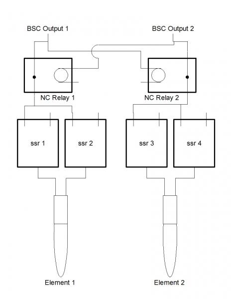
So if I follow this correctly, I would use a normally closed relay energized to the opposite BSC output. So Relay 1 would be energized by the BCS output for element 2 and Relay 2 would be energized by the BCS output for element 1. Energizing would open the relay killing the chance for the other to energize.

So I need to find a relay that is 5VDC? Will a 12VDC relay work so long as the control voltage is less than 5VDC?

Thanks,
Scott

Oh I know the drawing is not finished. I tried to only draw the parts I thought I needed quickly.

wiring.jpg
 
no, I wouldnt drive a relay coil with the output from the BCS. They cant provide much current and have no surge protection. Iirc they are tied directly to the micros outputs.

Instead you could find a relay with a 240V coil and use the power going to the elements to energize them. They would be on the output side of the SSR.

Lets say BCS output 1 is used to turn on SSRs1 and element 1.
Wire the coil of a 240v relay to either side of SSRs2 outputs, just like element 2.
Now take the BCS output 1, wire it to one side of the normally closed contact of the relay you just installed. Then take a wire from the other side of the normally closed contact and wire it to the SSRs1 inputs.

When Element 2 turns on the relay will break the control connection from the BCS to relay 2.
 
I still think it's reasonably safe to run one SSR per leg and carefully program BCS to only enable one element per state. Since you'll be switching both legs with separate SSRs, an SSR failure won't leave the element "on". If you screw up in programming and allow an overlap, it pulls 37 amps and trips the breaker. It's not like you're going to let that happen every day. It happens once and you figure out what programming problem is.
 
You may be right Bobby. I still think it is a cool idea to be able to wire this up to guarantee it never runs both. I can do it with manual switches, but what fun is that?


EDIT:
Ahhhh! I get it! Thanks coderage. In all my hand drawings I was never using the coil correctly. would probably take me too long to draw up with my crummy openoffice draw though.


Last question. The relay I would choose should I choose to go this way would need to be a 240VAC 30A relay correct? Those numbers correspond to the coil in the relay?


Thanks for all the help!
 
scoots,
the coil needs to be rated for 240V. The contacts dont need to be much at all, anything over an amp would be sufficient. All it is switching is enough current to turn the LED on in SSRs opto-isolators.

good luck!
 
Back
Top