Guys who have built PID controllers

Homebrew Talk - Beer, Wine, Mead, & Cider Brewing Discussion Forum

Help Support Homebrew Talk - Beer, Wine, Mead, & Cider Brewing Discussion Forum:

This site may earn a commission from merchant affiliate links, including eBay, Amazon, and others.

razor1115

Member
Joined
May 12, 2016
Messages
22
Reaction score
0
Hi guys,

I recently built a home brew PID controller modeled after Electric Brewery's control panel. I have a HERMS system.

I purchased 3 Inkbird PID controllers (ITC-100VH). My system is 240V, 5500W elements using PT100 RTDs. I have 40A SSRs.

I tried to calibrate the system in auto mode for the first commissioning of the controller. The RTD in the mashtun temp feeds the PID for the boil kettle to provide closed-loop control (as opposed to reading mash tun and HLT on their own, looking at the difference in temps, and open loop/manually setting my temp in my HLT to compensate for the system heat loss).

I set the SV = 64.4°C (148°F). The PV on the PID achieved the SV, and I would have expected some overshoot, then turning off the SSRs, allowing the temp to drop, then turn back on to zero in/ dampen the oscillations and understand the heat losses of the system.

The SSR never turned off, even when PV >>> SV. I let it keepp going up to 90°C, and the system never stopped powering the element. At this point, I set the Hi Alarm to a value (15°) below the current PV value of 85°C. The PID control went into alarm mode, shown on its screen. However, the NO relay in the PID did not trip the buzzer/lamp alarm. It appears the controller is faulty in not only controlling temp, but the relay NC alarm circuit also does not work.

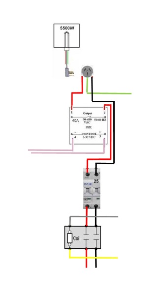
Can anyone find any issues with my diagram?

I have attached an abbreviated schematic of the HLT circuit to ask for help.

ITC-100VH Wiring.jpg
 
For the SSR output, is the CtrL mode set to 1, 2 or 3 rather than 0?
You could try setting the CtrL mode to 0 for testing, as then the system should work as a simple thermostat.

I also take it that the "Run" light is off, and that the run parameter is set to 1, so that it's not in manual mode.

For the alarm, is the ALP setting set to 0 (so the alarm triggers the AL1 output)?
 
On power up, following instructions of holding the << arrow more than 2sec never set PID into auto cal. I had to go into setting an write CtrL as &#8220;2&#8221; value, then it kicked into auto. After unsuccessful calibration, I set it back to 3.

Yes, run light was off (If I recall correctly - and it would have to be if it's not in manual , correct?), run = 2 automode

ALP = 0 as default from the factory

Here's the instructions:

http://ink-bird.com/asset/file/ITC-100_%20Manual_%20V1.0_6.30.pdf
 
Ive built many and have one going together now, I would use a contact relay to turn on the power to the element

in oder for the alarm to work you have to supply power to it

I'm not sure if you reviewed the schematic or not I use a relay the turn on the power to the element. additionally I have power run to the alarm
 
Worked out the alarm circuit - it's resolved.

However, element always remains powered on one leg coming from the power bus, even w/ the PID not powering the SSR that controls the other leg of the 240V circuit. I found this by removing the 120V leg that goes directly to the relay that powers the element.

So, it looks like, even with the SSR not powering the other 120V leg of my element, I always have 120V continuously power my element from the non-SSR controlled half of my 240V circuit.

It's wired just like everyone else's, so not sure why element stays powered when SSR is off....
 
Why does your element have a neutral wired to it? A 240V element should just get both hots connected to it, with one leg controlled by the SSR. The element should be grounded though, including the enclosure and metal vessel. Can you take a photo of your element and how it's wired?
 
Sorry - drew that up at work away from brew system. Same answer, 2 hots go to element, and the Neutral is actually a ground, ensuring if something shorts, all kettles are grounded and will not be live and waiting to bite me...
 
Worked out the alarm circuit - it's resolved.

However, element always remains powered on one leg coming from the power bus, even w/ the PID not powering the SSR that controls the other leg of the 240V circuit. I found this by removing the 120V leg that goes directly to the relay that powers the element.

So, it looks like, even with the SSR not powering the other 120V leg of my element, I always have 120V continuously power my element from the non-SSR controlled half of my 240V circuit.

It's wired just like everyone else's, so not sure why element stays powered when SSR is off....
 
If I'm understanding correctly, if your main switch is on, one side of the element will be hot straight from the contactor. You are only switching the other leg for control of the element.

Also, you will measure voltage through the SSR even when off. There will be a small leakage current but nowhere near enough to heat the element.
 
Got the chance to troubleshoot today - both SSRs are faulty and remain constantly on even with 12VDC signal wires disconnected. I have 120VAC on both terminals at all times, therefore the heating element was always 100% on.
 
Got the chance to troubleshoot today - both SSRs are faulty and remain constantly on even with 12VDC signal wires disconnected. I have 120VAC on both terminals at all times, therefore the heating element was always 100% on.
 
Got the chance to troubleshoot today - both SSRs are faulty and remain constantly on even with 12VDC signal wires disconnected. I have 120VAC on both terminals at all times, therefore the heating element was always 100% on.

Just so we are on the same page, you WILL measure voltage on the load side of the SSR even when off. This is normal and very misleading when testing with a voltmeter. The SSR stops CURRENT flow like a switch but unlike a switch, it is solid state and will allow a small leakage current. Also, the output terminal of the SSR is not physically disconnected from the supply terminal and will give you a voltage reading at the output.

If your element is actually firing with the control leads to the SSR disconnected, you have a faulty device. If you are only measuring voltage at the SSR output, it is likely that the device is fine. You need to test this with a load like the actual element or a light bulb to be sure.

Great post. All leadS to ssr disconnected and element still fires.
 
It's very rare to have two faulty SSRs. If you don't have a load on the SSR, it will leak voltage and that's most likely why you are reading voltage there.

Good post and info. Both + - ssr control leads disconnected and ssr still fires element
 
They wouldn't happen to be Fotek SSR's would they? There have been many counterfeit Fotek SSR's that are actually lower rated devices that have been relabeled as higher current devices. Lots of discussions on those over the past couple of years. I also got bit by one of those.

I would crack the SSR open and research the TRIAC part number inside. That's the part mounted to the heatsink plate. I wouldn't be surprised if it's a part rated for 20A or under.

EXACTLY the brand - I will crack one open...
 
New SSRs - left the VDC control wires off, no connection to the PID controller and yet they are still powering the element???
 
Reread Bobby's post again carefully. He doesn't mean not having the DC control signals connected. SSR's leak a tiny amount of current so you will always see some voltage across it.
 
Got the chance to troubleshoot today - both SSRs are faulty and remain constantly on even with 12VDC signal wires disconnected. I have 120VAC on both terminals at all times, therefore the heating element was always 100% on.

This is how it's supposed to be. In order for power to be delivered to the element current must be flowing. The SSR cuts off the flow of current when off, but you still have voltage on the element. That's why you need a 2 pole switch/contactor to disconnect voltage from the element for safety.

Electric current is analogous to water flowing thru a hose, and the SSR is like a valve. Voltage is like the water pressure in the hose. Think about a hose connected to fitting with a restrictor plate (the element) with another hose connected to the downstream side of the restrictor plate, and a valve on the downstream hose. Now put a pressure meter (volt meter) on either side of the restrictor plate. With the valve closed (SSR off) you measure the same pressure (voltage) on either side of the restrictor plate (element.) If you open the valve (SSR on), water (current) flows, and the pressure (voltage) remains the same on the upstream side of the restrictor plate (element), but goes to almost zero on the downstream side.

Brew on :mug:
 
Completely understand all this (I am an engineer). What I don't understand is why the element is heating while the SSR 12VDC control wires are completely disconnected and the SSR lamp is also off (which it should be with wires completely disconnected from the PID).

When I unhook one leg of the 240VAC circuit, either the one from the main power control relay that runs to one leg on each boil and HLT control relay, or I unhook the other leg that is controlled by the SSRs, the element stops firing (as expected just like it would if the SSR were turning off the leg of the circuit it controls). With them both wired according to the diagram, the element fires as soon as I energize the relay coil for each respective element. That's what has me stumped...

Failed SSR. Typical failure mode is shorted.

Brew on :mug:
 
I swear I posted in this thread. Was it the move? Am I banned? ;) Bad luck with two bad ssr's. I guess try a third. Maybe from a different source. Don't use those "made in China" ones they have a 66% failure rate :D
 
I swear I posted in this thread. Was it the move? Am I banned? ;) Bad luck with two bad ssr's. I guess try a third. Maybe from a different source. Don't use those "made in China" ones they have a 66% failure rate :D

Good info - I felt the same way! I ordered 2 SSRs and had this issue, troubleshot it, determined SSrs are the culprit. Ordered 2 more SSRs, although they WERE Fotek from a different supplier and still the same results.

I thought, no way 4 bad SSRs?? But the wiring is very simple and easy to follow, so I guess it's time to find some Auberins? Anyone recommend any other U.S. brands?

Try Mager SSR's from ebay. Auber just rebrands these, and the part numbers are the same. I haven't seen any reports of issues with Mager SSR's. Although if you are willing to pay a little more to get customer support, go with Auber.

Brew on :mug:
 
Back
Top