Semi-Automatic HERMS System (Work in Progress)

Homebrew Talk - Beer, Wine, Mead, & Cider Brewing Discussion Forum

Help Support Homebrew Talk - Beer, Wine, Mead, & Cider Brewing Discussion Forum:

This site may earn a commission from merchant affiliate links, including eBay, Amazon, and others.

bkloos

Well-Known Member
Joined
Nov 14, 2009
Messages
152
Reaction score
1
Location
Reading, MA
Hey Guys,

I thought I would post some pics of the system I am currently working on, and open up this thread for discussion and brainstorming.

My goal is to build a semi-automatic HERMS system capable of brewing 10+ gallon batches. The gas system will be fired with low pressure LP, and the fluid side will be controlled with pumps and solenoids.

I would like to start off by mentioning that many of the ideas for my brewery have been taken from other projects, both current and past, here at HBT. Of course, I must give credit to Lonnie as well for his Brutus 10!

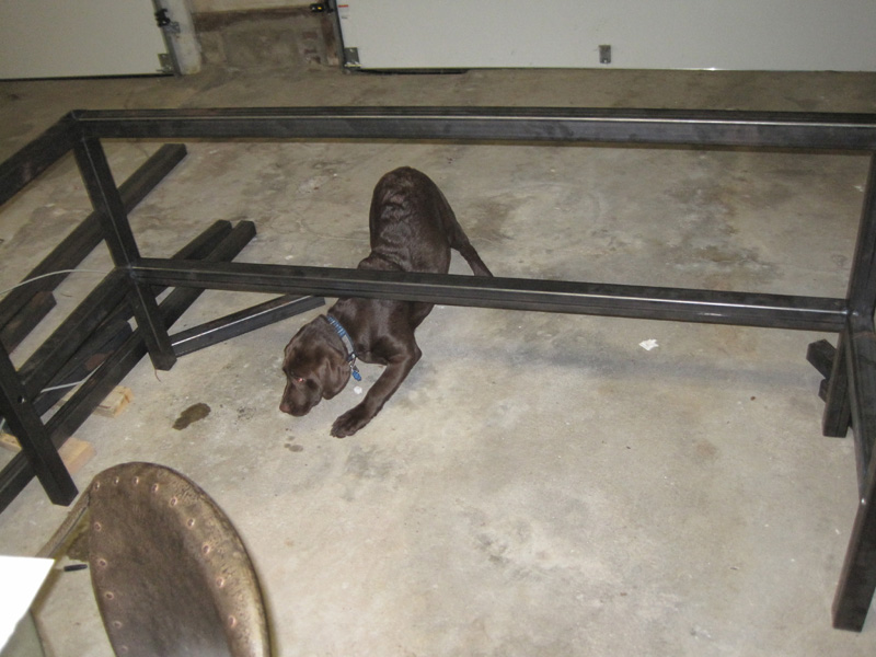
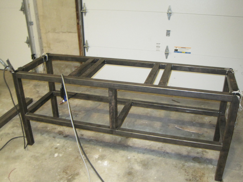
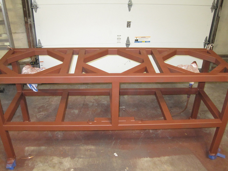
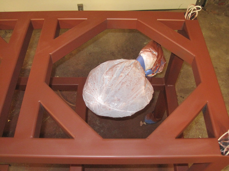
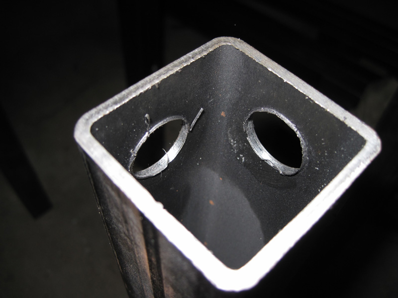
Here are some photos of the stand build. I taught myself tig for the build, and I am quite pleased with the progress thus far. Welds are solid, and the gas beam holds 25psi C02 for 24+ hours.
Picture 001.jpg


Picture 003.jpg


Picture 005.jpg
 
This is gonna be a great looking brewery my friend!

At this point I would only caution a few things that I see... Be careful with wire routing, making sure that you do not get it near the upper frame. I would exit any internal wiring at least 4 to 5 inches below the upper rails. It gets mighty hot up there! That heat travels down the legs a bit.

You may want to find a way to REALLY get your wort particle free before it reaches the solenoids. They will clog up with the very first particle. I loved this idea but I have seen others have problems with it and grain particulate getting caught in the pilot valve or the main opening of the valve. Sometimes it may not close and may have some grain stuck under the seal...

I know Palmer had a heck of a time with this.

Looks like a GREAT build my friend... The welding looks as good as it gets! Please keep the pics coming!
 
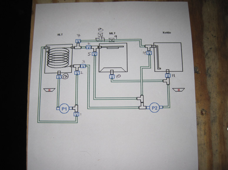
The fluid side is based on the flow diagram of the Blackheart Brewery with a couple modifications. I plan on keeping all my solenoids and pumps below the kettles on the lower tier of the stand. I will use flex hose to connect to the inputs/outputs from the manifold the kettles.

I'm currently trying to decide how/where to mount the control box. I was thinking about putting it on the right side of the brewery, on a hinged swing arm similar the Lehr's rig... TBD.

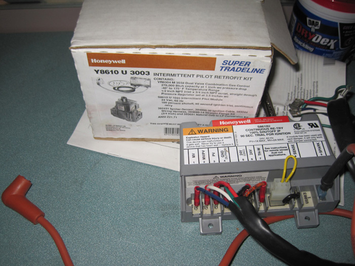
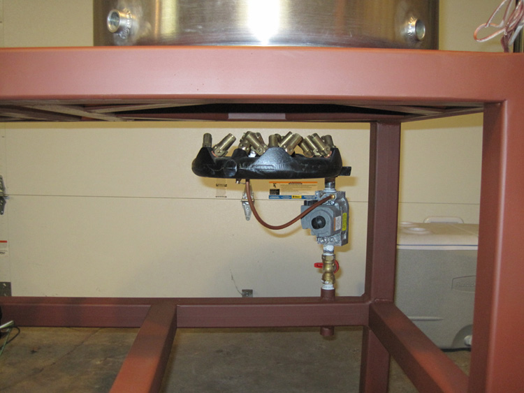
The burners are 23 tip jets. The HLT is controlled with a honeywell furnace and intermittent pilot, and the BK is plumbed with an ASCO and fixed pilot. I will probably install a push-button ignitor if I don't use the constant pilot.

I will also have water inlets for the BK and HLT, which will be controlled with solenoids, passing the water through carbon filters.

One thing I may do is incorporate 2 HXs in the HLT, one standard HX for wort circulation (heating and cooling) and the other for running cold tap water to cool the HLT after the boil to increase cooling capability before adding the ice.... Again TBD.

As it stands now, I need to clean up the layout of the manifold and mount the pumps. After that I will begin drilling and welding up the kettles (20 gal SS pots for the BK and HLT, 14 gal for the MT). After that I will start work on the control electronics.

The electronics will be push button control for the various processes (Dough in, Circulate, Sparge, Boil, Cool, out to fermentor etc etc) as per the blackheart brewery system. For now it will not be PC controlled, but I will keep that as an option down the road.
 
Hey Guys,

So here is where I hope the "brainstorming" begins...

I'm about to start tweaking to layout of the manifold to find the most effective use of space and gravity for priming...

I would like to know your thoughts with regard to the pumps orientation while mounting...

I will be using 2 march 809s. Is it acceptable to mount these vertically (so the fan is under the pump head) or do they need to be mounted vertically?

Once the build is complete, I will fab a cover to enclose the pump/manifold setup, so water/wort dripping down the pump should not be a factor.

Thoughts?

Bryan
 
Hey Fellas,

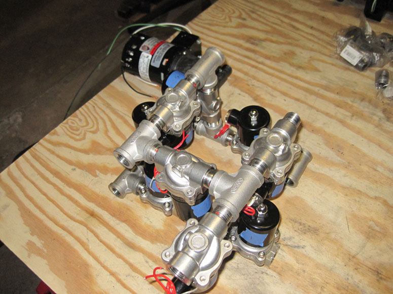
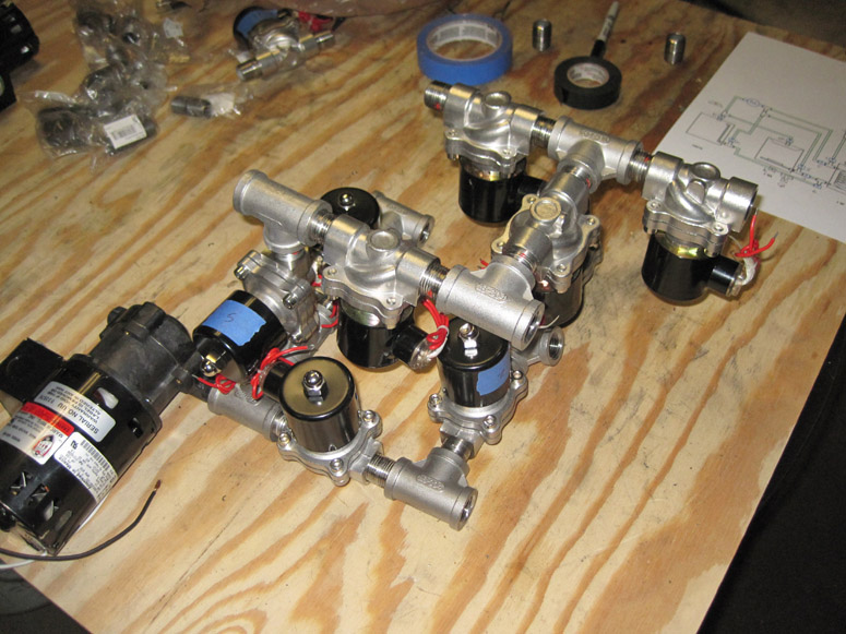
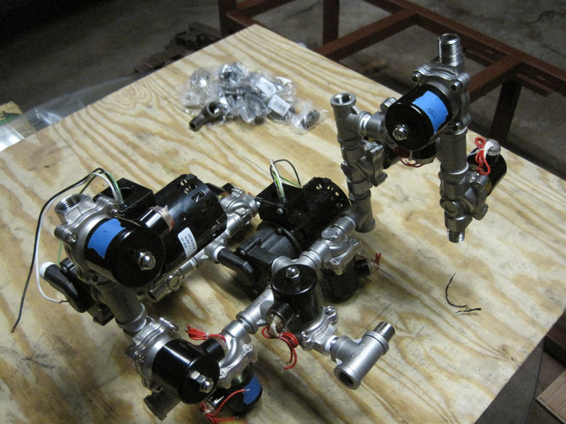
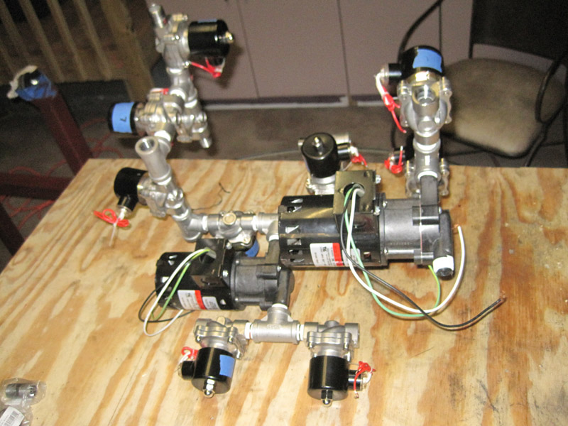
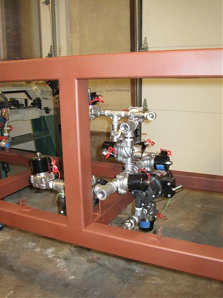
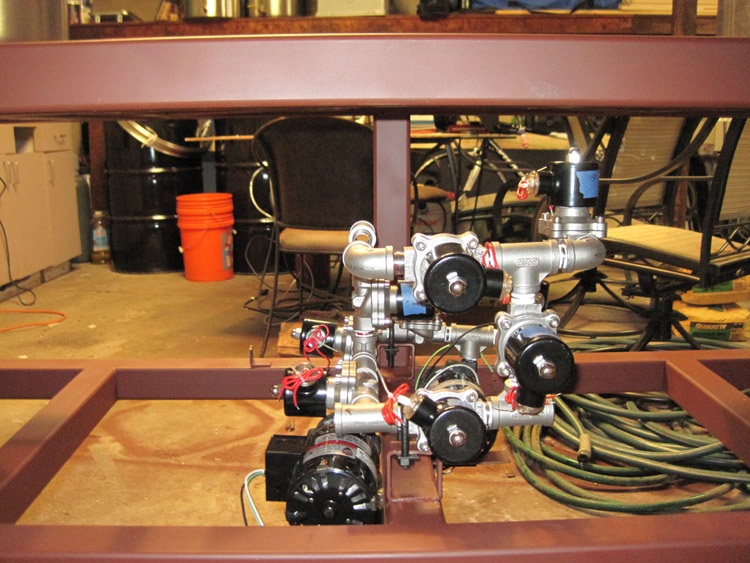
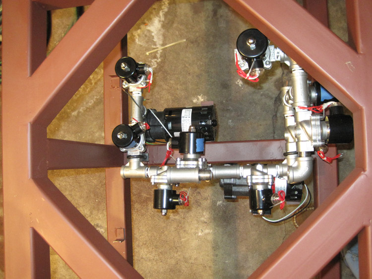
I've experimented with they manifold layout and I have a compact orientation that I think will work.

As you can see, I'm following the liquid flow diagram of the Blackheart brewery with the addition of two valves so I can pump to the fermentor without having to disconnect anything. As mentioned, the goal it to keep the entire manifold below deck thus eliminating solenoids hanging off the kettles....

After looking at my layout, it seems that I may need a dump valve to fully drain the lines after the brew session. The original plan was to run water and then sanitizer through the lines/manifold after the session to clean everything out. BUT, if my manifold is below deck, any liquid in the lines will drain into the manifold and stick around until the next brew session... Not good for many reasons. Do you think I should add a manual dump valve at the lowest point for cleaning purposes?

I could easily add a switch on the control panel to open all valves simultaneously after cleaning/flushing and then drain from the dump at the lowest point via gravity. Does this make sense???

Thoughts?

Thanks,

Bryan

Picture 002.jpg


Picture 003.jpg


Picture 004.jpg
 
Make sure you have access to the tops of the solenoids even with full kettles. I would also add a manual valve on each kettle. Lonnie made a very valid point about grain particles. There may come a time when your kettles are full and you have to take apart a solenoid and clean it to get it working again.
 
Thanks for the advice Beerthirty.

I was thinking about closing up the manifold with a removable panel. I will be sure to keep the panel "removable." I may also keep things exposed, pending how they look.

I will also orient the solenoids in such a maner that I can pull the tops in an emergency... Good point!!!

WRT particles, what is the best method to ensure no grain gets into the works??? How big of a particle are we talking about here? I'll have a false bottom and a screen over the pick-up tube. Would this suffice?
 
The manifold is finished, with the exception of needing a few QDs and one connecting tube.

It's pretty wild looking :rockin:

While this layout is a bit larger than my previous version, it has the pumps facing up/down so tha I can use gravity to prime (at least in theory).

Next step is to lay the manifold onto the frame and fabricate some supports for the pumps. I was thinking about using these (the vibration dampeing type) attached to some square tube. They look pretty slick.

Looking at the march specs for the pump, I should be able to get 4.3 max feet of head. I'm wondering how much that will decrease with the 90 degree turns in the manifold? Have you guys had any issues with flow rates with bends and a couple feet of elevation?

Moving along, slowly, but moving!

Picture 003.jpg


Picture 001.jpg
 
WRT particles, what is the best method to ensure no grain gets into the works??? How big of a particle are we talking about here? I'll have a false bottom and a screen over the pick-up tube. Would this suffice?

The particle size is dependent on your mill but think flour. I would be concerned with the surface area on a screen over the diptube. How about a screen over the false bottom.
 
Working along, keeping busy;)

I am about to place an order with McMaster and I am now thinking about coils for the HXs.

I've seen the SS coil, McMaster # 8989K98 for about $70. Has anyone used this coil, and if so how pliable is it? I know the product description states it will bend with a bending tool. Does it work well with compression fittings?

Am I missing something, or is copper tube about the same price as the SS???

I'm at a crossroad with respect to stainless versus copper/brass. Thus far, all the fluid side of the brewery is stainless other than some flex hose that I will use. I'm not realistically going to be able to afford SS quick-connects for the system at this point, and I'm leaning towards these brass QDs. I would like to eventually have the system all SS, but I won't mind using some copper/brass in the near term as long as I can change out for SS down the road....

So, copper or SS for the HXs?

Bryan
 
Hey Guys,

I've found the 50' coil of 1/2" SS tube for near $50, so I am going to go for it...

I have a design question I would like to ask some assistance with:

For cooling wort post boil, I am planning on circulating through the HX in the HLT which will be filled with fresh cold water. I am toying with the idea of adding another HX in the HLT for circulating cold tap through during this cooling period. Once the wort temp is down to near tap temperature, I would turn off the second HX circulating tap and drop a few gallon containers of ice into the HLT and continue to circulate to get my wort down to pitching temp... At least in theory. Does this sound like a good idea?

All help is greatly appreciated!

Thanks,

Bryan
 
Check out The Pol's "Closed System Wort Cooling" thread. He did a bunch of research and testing and it seems to work well.

Also mind sharing your source for SS coil? I'm getting ready to build a HEX.
 
Crushed ice it will be.. I'll also look into those links.

I was wrong about the SS cost. I was looking at 3/8", not the 1/2".

I'm searching around for a cheaper price (currently available on ebay for $69.95). I will report back when I have some more information.

Thanks!

Bryan
 
Hey Guys,

I' puled the trigger today and purchased 2 50' coils of 1/2" stainless tube from here.

I was told the tubing is rather rigid but, and I will report back once I've worked with it. Seeing as I won't need to make any tight turns, I think it should work out well for my application. Worse case scenario is a trip down the street to use a proper bender...

They were nice to work with and the price was right!

Info to come.

Bryan
 
Steel has arrived, and I'm in the midst of trying to bend it into shape.

Before I get too far with the bending, I would like to get your opinion regarding the length of the HX coils in my HLT.

I will have two HX coils in the HLT: 1 for circulating the wort during the mash, and the 2nd for circulating cold water during chilling. What do you think is an adequate length for the coils? I don't want to run 50' each if the temp equilibrium will be met with 25'. Is the full 50' overkill?

In an ideal world, I would prefer to use closer to 25' for the HXs.

Lastly, where are you guys sourcing your elbow and straight swageock fittings?

Thoughts?

Bryan
Thanks,

Bryan
 
Why do you need two coils? Just use the HX coil for the cooling???

I would put 25' in the HLT.

eBay is by far the cheapest source for stainless swagelok. Find the product numbers of what you need on swagelok.com, then search those numbers in eBay.
 
Post boil during the chill, I plan to recirculate through the same coil in the HLT used for maintaining mash temp. The HLT will be filled with fresh cold water, but as the wort cools the HLT water temp will increase. I will have the second coil in the HLT to dump off some of that heat. Once the wort is near 80F, I will dump in some ice to help get me down to pitching temps... Think of it as a permanent immersion chiller in the HLT.

I'll poke around ebay with the part numbers...

Thanks!
 
A picture is worth a thousand words, and I cant draw;)

In a standard herms devoid of an immersion chiller, how does one usually chill?

I was thinking of recirculating wort from the BK through the HX in the HLT. I thougt the HLT water would heat up as the wort cooled, correct? Once this equilibrium is reached, heat transfer would cease. At this point you could dump in a bunch of ice to further cool the water in the HLT which will further cool the wort circulating through the HX.

My idea was to have a second coil in the HLT that would circulate tap water to keep the HLT water cool as the heat from the boiling wort was transferred to the HLT. I thought this would increase the rate of cooling? Maybe it is a waste of time...?
 
Hey Guys,

I'm about to start drilling and welding up the kettles and I need to source the swagelok fittings for the HX and various other pick-up and inlut tubes.

I will need several 1/2" MPTx1/2"Tube fittings, some straights and some 90 degree elbows:

SS-810-1-8
SS-810-2-8

I've been searching around on ebay and see them at all different prices... What do you guys think is a fair price for these fittings?

Thanks,

Bryan
 
Hey Guys,

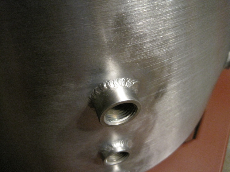
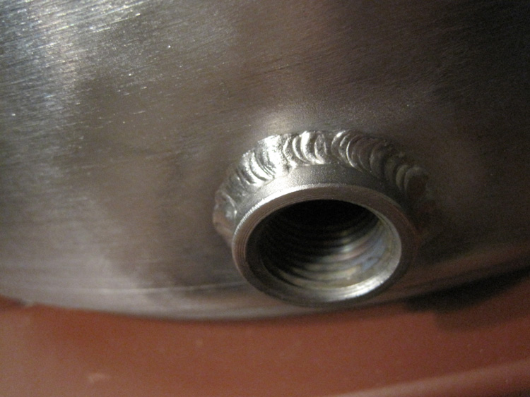
I've just about finished welding the kettles with full and half couplings for my various components... I'll get some picks up by the end of the weekend. Unfortunately I need to order a few more couplings as I didn't account for the sight glass locations.. Oh well!

This has led me to a new question. I am wondering what is the best way to install thermowells in the kettles. Specifically, I want to know what types of fittings would work best. I have 1/2" couplings on the kettles, and was thinking about using swageloks and 1/2" ss tube tigged closed at the end. Would this work well? I've also seen shielded thermocouples which protect the thermocouple wire. What's the best way to fashion such a component?

What have you guys done for your rigs?

What works best?

What would you avoid?

Thanks

Bryan
 
Thanks for the links. I was looking at Derrins products. They look very nice. I may try to build my own just for the hell of it... TBD. If I go comercial, I will jump on this option, as the workmanship seems to be top notch!

The brains... This will be the last big chore of the build. I have a bunch of ideas which I will put out here soon enough.

Basically, I was thinking about having a rotary switch that I can use to select between the various processes (dough in, recirc, sparge, sanitize, chill, pump out to fermentor, etc). The rotary switch would activate a mechanical relay which would then opperate the necessary valves in the manifold and pumps for that specific process in the brewery. As the brew day progressed, I would simply rotate the rotary switch to the next position for the subsequent process...

I also plan to implement manual overides for the valves to open them all up at once for cleaning the manifold. That, and I would have lights on the panel to indicate the opperational status of each valve duing a specific process. I also plan to have digital temp read-out for the BK, HLT, MT, input of HX and output of HX using cheap digital temp panel mount meters...

I am sourcing some variable flow electric ball valves similarly to what brewmoor has been playing with for controling sparge rate, and will use a float switch to control the pumping in of the sparge water.

Lots of ideas, but still a little ways away...
 
You've probably seen it but the BrewTroller (http://www.brewtroller.com) would fit in pretty well here. You can always add in switches for manual override as well.

I have one (just now in the process of installing my solenoid valves) and the development has been pretty impressive over the last year or so. It's very customizable too if you're a little tech savvy.
 
I like the brewtroller, but would implement at a later date. I'm planning the electronics such that I can add full automation down the road. All the guts will be there should I want to add in a brewtroller....
 
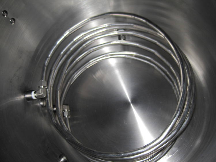
As promised, here are some shots from the recent weekends work. I tigged up the couplers on the HLT and BK, and installed the SS HX coil. As you can see, the coil is not that pretty. I used the thin walled SS tube on ebay, which was a good price, but is tough to bend. I added a few degrees of arc every few inches to tighten up the radius of the coil. May not be beautiful, but it will work ;)

I'm pleased with the welds, given this was my first real attempt at SS w/tig.

I may opt for a better HX coil down the road, but I still have a lot of things to finish before I start "perfecting" the system.

Next up will be the thermowells, which I will fabricate later this week, and then the sight glasses. After that will be water filtration and control, and then on to wiring.

So much to do, so little time!!!

1.jpg


2.jpg


3.jpg


4.jpg


5.jpg
 
And here is the manifold as it currently stands. I will enclose this with sheet to "protect the goods" which will tidy things up a bit, though I kind of like the Frankenstien think going on....

The burners are also complete and ready for wiring. I have the HLT controlled by a Honeywell furnace valve, and the BK by an asco. I will probably upgrade the Asco to another honeywell if I can find the components cheap enough, given that I will heat the strike water in the BK before I dough in. Temp control will be nice here.

7.jpg


8.jpg


9.jpg


6.jpg
 
Code:
Can you say what model and where to buy the valves you are using?

I bought my valves from Duda Diesel. Good prices, good seller. I am using the 110 VAC, 1/2" valves, seen here.
 
Many Thanks!

I've got a long way to go!

I finished the kettles last night, installing drain pick-ups, T's opn the outside of the HX, sightglass (minus the sight glass, and inlet fittings. Still need to figure out the thermowells.

I ordered some tubing and such to make them, but unfortunately picked the wrong SS nipple, so I am back to the drawing board which may now involve a simple purchase...

That said, what is the preference for commercial liquid tight PT100 based RTDs???

Auber has some with 2" and 4" probes that would fit the bill, while I have also seen less expensive products such as these.

I will need 5 total (HLT, MT, BK, and 2xHX) so lower cost is a good thing. BUT, I love the break-away cable connectors of the Auber!!!

What have you guys used and what do you like?
 
Delays Delays.... Alas, no more delays...

I had two 55 gallon steel drums taking up too much space in the garage, so I decided to do a little cleaning, and built this. Cant wait until some of this rain lets up and I can break it in. Nothing quite like Q and home-brew!

Anyhow, I'm back on the build :ban:

With some assistance from the tax-man, and my new home buyers credit, I will be sourcing the brass qd's, high temp silicone tube, and various electronics for the control. Should have most of the goods in a week or so.

In the interim I built up the kettle fill manifold and filter setup. I have a garden hose female which feeds an in-line filter and then feeds two asco's so that I can fill the BK and HLT on the fly. Unnecessary, but cool none the less...

I'll get some pics up in a few days.

Otherwise, all is good!
 
Back
Top