Would you be willing to post a few more photos of this setup. I am interested in a pic of the grounding setup and a pic of the inside of your kettle with element installed. Are you using the 1" nut and weld less gasket from bargain fittings. Thanks in advance. I believe this will be the route I go down. Last question if where the ground wire is anchored gets splashed or if condensation occurs nothing bad should happen because there is no current going thru it right? I'm obviously no electrician
You are using an out of date browser. It may not display this or other websites correctly.
You should upgrade or use an alternative browser.
You should upgrade or use an alternative browser.
element cover
- Thread starter McCuckerson
- Start date

Help Support Homebrew Talk - Beer, Wine, Mead, & Cider Brewing Discussion Forum:
This site may earn a commission from merchant affiliate
links, including eBay, Amazon, and others.
What holds the pvc cap onto the element? Unless I am missing something, your approach does not seem to provide much strain relief.
I would have to agree. This method seems to provide no strain relief.
The conduit grip is threaded into the cap. The cap bottoms out on the element hex and the grip is clamped to the cord. Its not rigid like when potting the adapter method, but its not flimsy either. I just think the electrical box method is overkill, and potting is a pain. Cheers
So the tension of the wire between the element terminals and the cord grip holds the cap in place?
What happens if you snag the cord or bump the cap during a brew? It seems like it wouldn't take much force to pop the cord and the whole assembly free from the element. The heating element terminals aren't really designed to hold a wire under tension.
Kal's method or the electrical box method is a bit more effort and $ but it provides strain relief and it is easy to change out an element if it goes bad.
shroomzofdoom
Well-Known Member
One issue with these is that they can be over tightened and short the wires inside and the nut that holds them in place can loosen with usage. In my March pump toolbox, I've had to tighten these on occasion.
I really like Kal's setup but my concern with his junction box is that the box could get knocked and possibly come loose and could get liquid inside, not sure if this is a legitimate concern but was the first thing I thought of when I saw it.
Very few options here are 100% but a weld/triclover or potting with jb are pretty close.
Any reason that this couldn't be done with an S.S. cap?
samc
Well-Known Member
I wonder if you would be able to ground the wire to the conduit grip?
The conduit grip is not in any way bound to the the kettle, so it would not be grounding what you want it to.
FrFtr28
Well-Known Member
So, I tried this method last night and ran into a problem. The conduit grip came into contact with one of the terminal rings connected to the element, but I couldn't tell since it was on the inside of the PVC cap. As you can guess, when I sent power to the element, the metal to metal contact caused a short tripping the GFCI breaker and causing my SSR to explode. Just wanted to give everyone a heads up and maybe keep this from happening to anyone else.
Looks like my inaugural brew with electric will have to wait for another SSR to be delivered.
Looks like my inaugural brew with electric will have to wait for another SSR to be delivered.
FrFtr28 said:So, I tried this method last night and ran into a problem. The conduit grip came into contact with one of the terminal rings connected to the element, but I couldn't tell since it was on the inside of the PVC cap. As you can guess, when I sent power to the element, the metal to metal contact caused a short tripping the GFCI breaker and causing my SSR to explode. Just wanted to give everyone a heads up and maybe keep this from happening to anyone else.
Looks like my inaugural brew with electric will have to wait for another SSR to be delivered.
You should always perform a continuity check with a multimeter between all combinations of wires before you turn anything on. You should never have to rely on your GFCI. You would have measured a short and known something was wrong before you fried your SSR.
McCuckerson
Well-Known Member
I doubt that was your problem. The conduit grip is not a current path, it goes nowhere. If the the grip shorted across both terminals, then you got a problem. But still, the short would be at the element not the SSR, so why would the SSR blow? I would definitly ohm out that circuit...
FrFtr28
Well-Known Member
If the the grip shorted across both terminals, then you got a problem.
That's what I think happened. When I removed the PVC cap, the inside was blackened along with one of the terminal rings. As far as the SSR blowing, not sure why that happened, maybe somebody with a little more knowledge can chime in. I tested the SSR before and after this happened with a 40 watt light bulb and it worked both times.
I ended up bypassing the SSR and removing the PVC cap to test the circuit and it worked fine.
Once the new SSR gets here I will double check everything with an ohm meter before I fire it up again.
McCuckerson
Well-Known Member
That's what I think happened. When I removed the PVC cap, the inside was blackened along with one of the terminal rings. As far as the SSR blowing, not sure why that happened, maybe somebody with a little more knowledge can chime in. I tested the SSR before and after this happened with a 40 watt light bulb and it worked both times.
I ended up bypassing the SSR and removing the PVC cap to test the circuit and it worked fine.
Once the new SSR gets here I will double check everything with an ohm meter before I fire it up again.
Ok, let us know. If this proves to be an unsafe method we will have to post that. I have been using it for 9mo without incident.
Did you put the black gasket between the pvc cap and element as shown in the photo? If not, maybe that provides the clearance?????
FrFtr28
Well-Known Member
Did you put the black gasket between the pvc cap and element as shown in the photo? If not, maybe that provides the clearance?????
No, I used it between the element and kettle. Also, I think the cap I used may have been shorter than the one in the photos, so that didn't help either.
McCuckerson said:I doubt that was your problem. The conduit grip is not a current path, it goes nowhere. If the the grip shorted across both terminals, then you got a problem. But still, the short would be at the element not the SSR, so why would the SSR blow? I would definitly ohm out that circuit...
If the conduit grip shorted both terminals then all of the current would flow thought the conduit grip and no current would flow through the element. The element and conduit grip would be connected in parallel and the conduit grip would have significantly less resistance less than 1 ohm whereas the element has over 10 ohms resistance depending on its wattage. Electricity will take the path of least resistance therefore it will go through the conduit grip and not the element. Therefore the element will not blow. The amount of current flowing through the conduit grip would exceed that of the current rating of the SSR which will cause the SSR to blow.
Edit: you would still have the usual 23 amps flowing through the element if it is a 5500w element. But in addition the conduit grip would be able to allow a lot more current to flow through it. Say the path through the conduit grip is 0.1 ohms then theoretically that would draw 2400 amps through it. Obviously that much current would never actually go through it as circuit breakers would trip first or in your case the SSR blew because it can handle that much current.
grandequeso
Well-Known Member
I did something similar to this with the plastic cap, I'm not real happy with it, I plan on swapping it out with something like Kals boxes when I get the time.
To the guy who knocked out his ssr. Once you fixed your short circuit at the element, if you really want to brew this weekend, you could just plug your hlt kettle into you boil kettle's plug & then just swap it out when you are ready to boil. You really only are only ever using one pid at a time. I've had to do something similar once when I tripped over a temp probe cable in the middle of a brew & broke the cable. This is all assuming that your have a system with two pids?
To the guy who knocked out his ssr. Once you fixed your short circuit at the element, if you really want to brew this weekend, you could just plug your hlt kettle into you boil kettle's plug & then just swap it out when you are ready to boil. You really only are only ever using one pid at a time. I've had to do something similar once when I tripped over a temp probe cable in the middle of a brew & broke the cable. This is all assuming that your have a system with two pids?
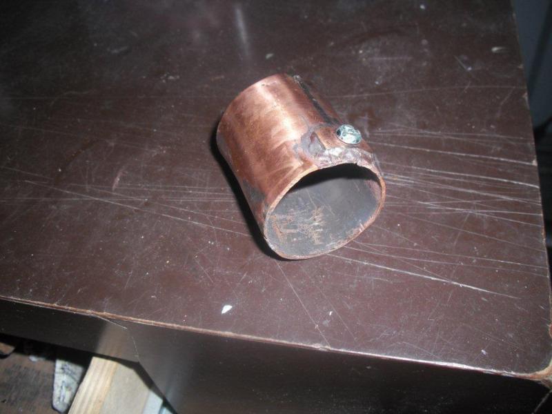
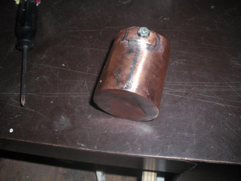
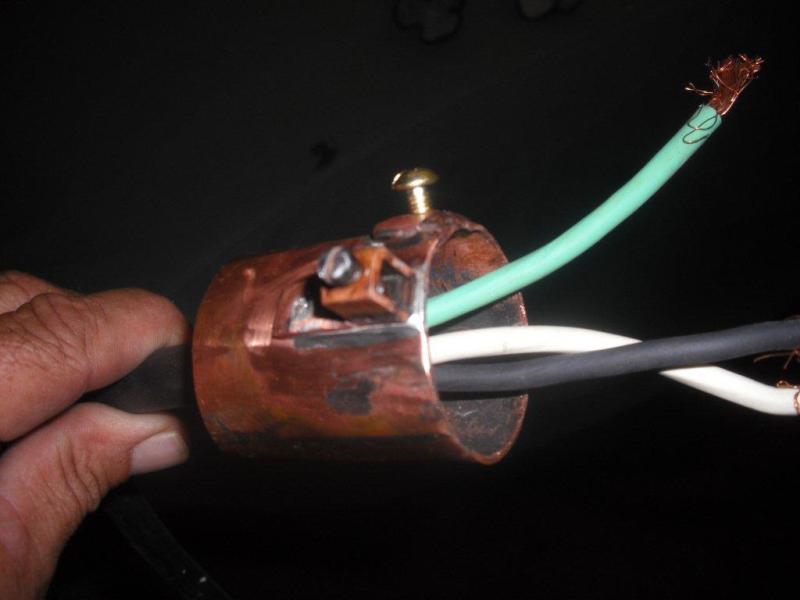
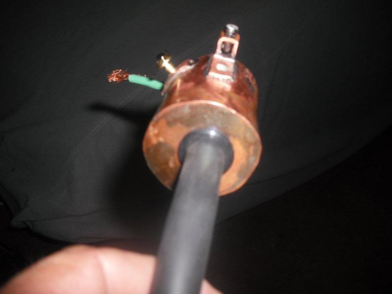
Here is my temp. one 11/4" female pvc conduit connector it fits good but I have a rubber O ring on the boiler side,if I was going to keep it I would have cut some slit on the boiler side and put a hose clamp to secure it ... I decided to make a better one from copper with a set screw , this is not finished yet


McCuckerson
Well-Known Member
I like it. A bit more work than I wanted to undertake, but I do like it. Your method provides more strain relief than mine. 

I did my setup very similarly to the original picture on the first post although I used enough clear silicone to seal it waterproof. After about 10 brews I added a bit more silicone as it was cracking with movement(cleaning the keggle). Although I will probably take it apart and inspect it now.
I also blew a SSR but without damage to anything else. It was just because I was using a cheap Chinese eBay Fotek SSR. I have replaced the SSR and had no problems since.
I also blew a SSR but without damage to anything else. It was just because I was using a cheap Chinese eBay Fotek SSR. I have replaced the SSR and had no problems since.
McCuckerson
Well-Known Member
Here is how it ended up,The rubber grommet didnt work out so I soldered a 1/2" 45 for strain relief, and put on twist locks for quick connects
Nice job! Looks solid as hell:rockin:
KitB said:I have to believe that the approach you're referring to is to:
A) Rock & roll, all night.
&
B) Party every day.

I like to rock and roll "part of" every day.
My way looks ugly but I thinks it's sealed up fine. The vinyl tape you see is actually covering self fusing rubber tape. It has to be carved off with a knife after a heat cycle; don't know about before a heat cycle. One step better would be to pot it in with the stuff used for underwater connectors.


Similar threads
- Replies
- 7
- Views
- 517
- Replies
- 25
- Views
- 1K


