Fermenter Cooler project

Homebrew Talk - Beer, Wine, Mead, & Cider Brewing Discussion Forum

Help Support Homebrew Talk - Beer, Wine, Mead, & Cider Brewing Discussion Forum:

This site may earn a commission from merchant affiliate links, including eBay, Amazon, and others.

fish4fun

Active Member
Joined
Oct 23, 2009
Messages
38
Reaction score
0
Location
supply
I have been playing with an idea using a TEC (ThermoeElectric Cooler) for chilling/heating a fermentation vessel. These little semiconductor devices offer ~85W of cooling/210W of heating at a very low initial cost (< $ 0.10/W) and a high degree of temperature separation from ambient (~60C). Honestly associate fans/heat sinks/insulation are more primary costs. The general idea is to build a cost effective temperature controlled environment for fermentation. While I fully intend to explore the venue for my own purposes, I am curious if such a device would be of interest to others.

Fixed costs of such a cooler would be the TEC & heat sinks, the PS, the "box" and the controller; variable costs would be the size of the box, the amount of heat removal (cooling) and the fit and finish of the "box".

Everything I am talking about can certainly be achieved with a craigs list freezer and an external thermostat, perhaps for less money. The cost of a 6 gallon carboy sized device would be close to $200, but the cost of a 1/2bbl Sankey keg sized device wouldn't be much more (perhaps $250). The advantage to individual fermenter coolers would be independent temperature control and space savings (pick a temp between 32F and 86F with +/- 0.25F or greater resolution and +/- 0.5F accuracy) with data logging for the entire fermentation process (180 days or more in user selectable time increments easily imported/monitored with a PC.)

I am curious if anyone would be interested in such a cooler @ ~$200-$300; or, if anyone would be interested in an open source project of basically the same cost basis. (Honestly in "production" the cost (w/o shipping) of a finished unit would probably be less than DIY). The finished dimensions of the cooler would essentially be the fermenter vessel + 4in in all planes except the "top" where the "internal box clearance" would need to be height + ~9in.

The expensive parts of the system would be:

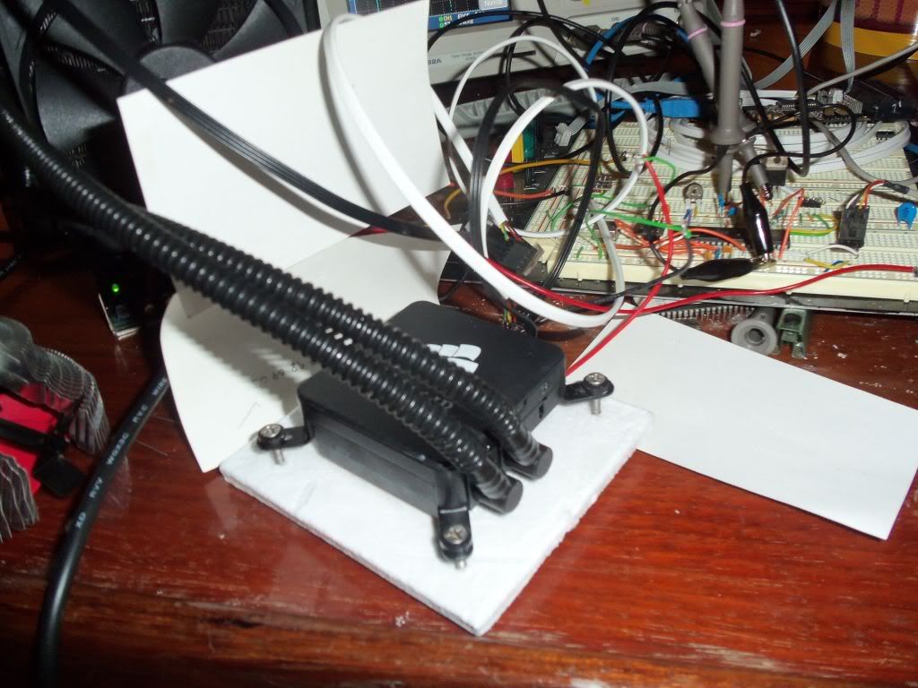
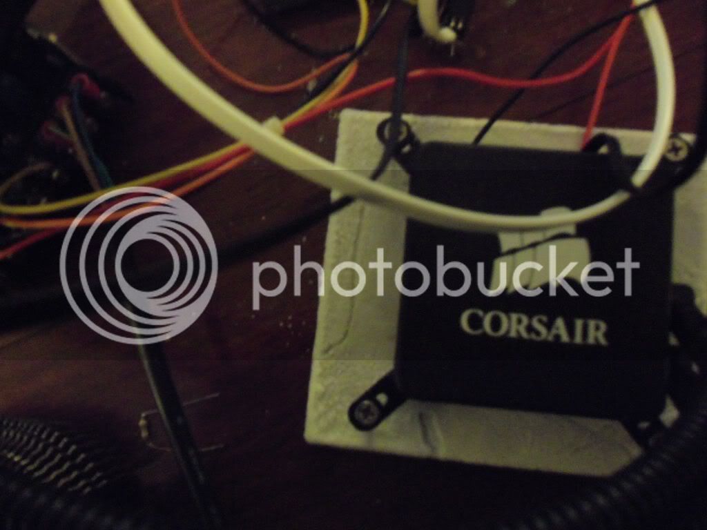
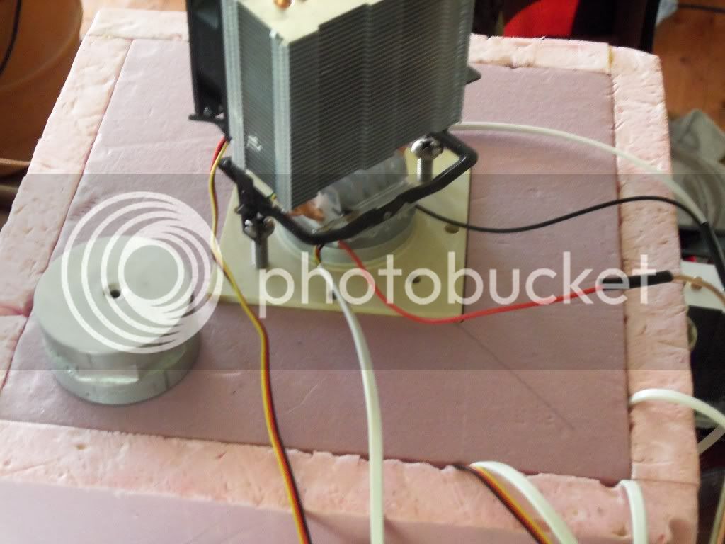
1) The liquid heat Transfer System (~$70)
2) The Pourable Foam used for insulation/construction(~$60)
3) The Power Supply (~$25)
4) Cosmetics ($20)
5) The Cooling Fan & Heat Sink ($15)
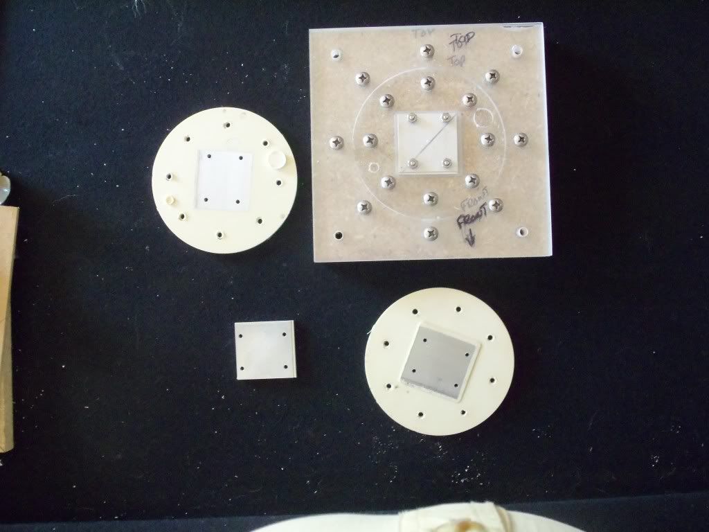
7) The Misc Alum parts (~$15)
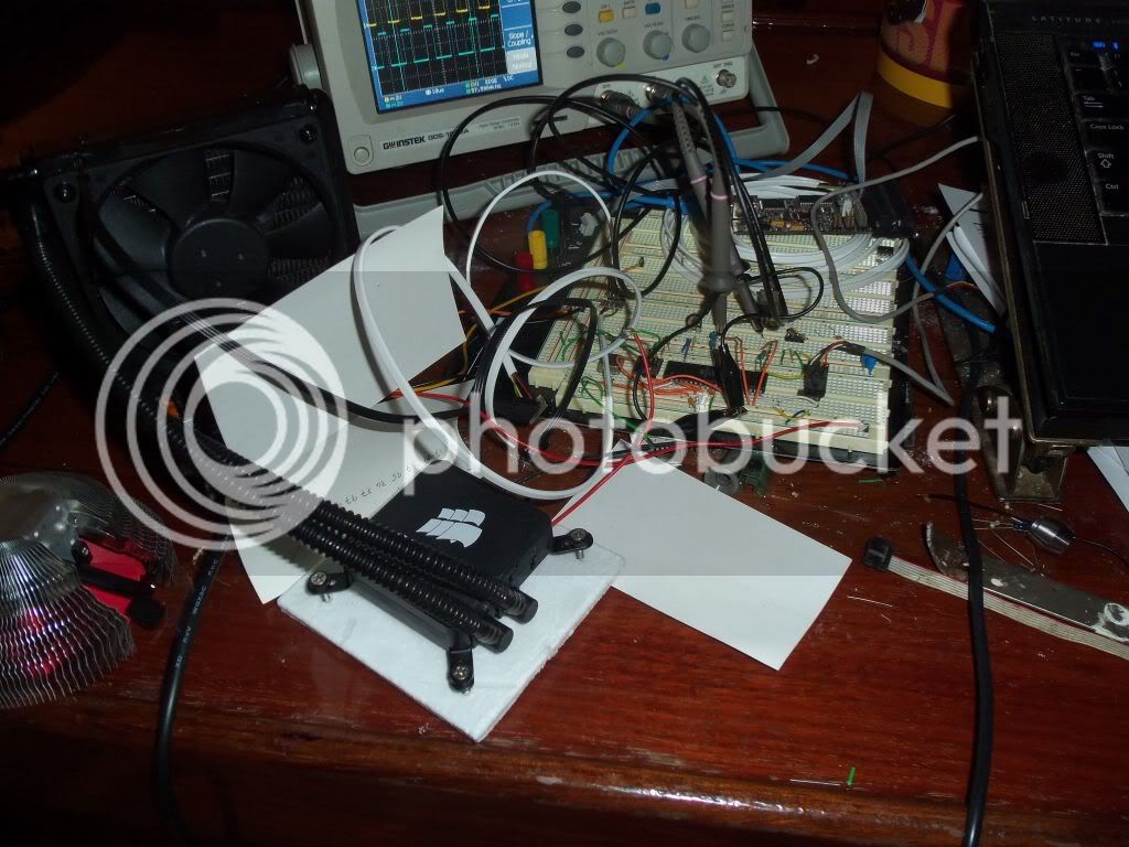
8) The uController PCB & Components (~$15)
9) TEC (~$7)

The mold for the foam (with a modest CNC router or careful hand work) shouldn't cost more than ~$50 in materials. The various "finishing" parts should be trivial in material cost, but would require either careful hand or CNC processing.

Obviously the cost estimates DO NOT include the fermentation vessel, and as the volume of the fermentation vessel increases the various costs associate with construction increase (but with some economy of scale, eg, the FOAM & "finishing" components increase as volume increases, but the power supply, cooling fans & heat sinks remain fairly constant).

While I plan to follow this project through to a few finished units for personal use regardless of other interest, I am curious if others might be interested in 1) an open source project where the design, PCB, firmware/software and construction were documented, or 2) where the finished product were offered for sale. The two are NOT mutually exclusive. I have a day job, and am not looking to support myself from this endeavor; if I made these units for sale it would be on a hobby scale, much like a wort chiller: any profit would come from purchasing materials in bulk. The primary advantage to individual cooling units for fermentation would be to those interested in simultaneously fermenting different batches at different temperatures, or for people who have space restrictions. From an energy point-of-view a TEC (peltier cooler) is ~ 80% less efficient than a conventional liquid based heat pump, but they are far less expensive to construct than a similarly sized heat pump on a small scale. TEC cooling requires CONSIDERABLY less daily effort than "ice" based cooling but is otherwise similar in cost of construction, and perhaps less expensive from an energy foot-print point-of-view.

Again, the project does not involve "magic", and there are certainly ways to achieve the end result less expensively (eg a $50 craigs list chest freezer and an external temp controller), but if there are people out there who are interested in fermenters with a small footprint, exacting temperature control AND logging with minimal effort then perhaps this project is of general interest.

Thanks in advance for any comments or responses :)

Fish
 
If I read this correctly, the peltier cooler is 80 % LESS efficient than traditional refrigeration?

You pretty much had me right up until that.

I would love two fermentation vessels, one to ferment in and one for lagering. Tracking and logging temps intrigues me, too. Did I just misunderstand your post about the efficiency?
 
muthafuggle,

Did I just misunderstand your post about the efficiency?

Sadly you did not; peltier cooling is roughly 80% less efficient than refrigerant based cooling; however, this does not mean such a device would make your electric meter spin like a top. A worse case scenario would be if the cooler had to run 24/7. Since the max power input to the cooler is ~150W (including pump & fans), assuming the power supply is at least 80% efficient this would imply a maximum power consumption of 150/0.80 < ~190W. (190W/ * 24Hrs * 30days * $0.12/kWh)/1000W/kW = $16.41 per month. In a more realistic example where the cooler cycled on only 5 minutes per hour a 30 day cost of operation would be < $1.50. If you compare this to the cost of an ice based system that required 4kg of ice per day (roughly one gallon of ice frozen in your freezer), the energy required to freeze the water would cost ~ 15.3kWh * $0.12/kWh = $1.84. (This is derived from: 30 Days * 4L * ((1Kg * 4.182kJ/kg * 25C) + 334kJ/kg + (2.11kJ/kg * 10C)) = 55,080kJ/3600seconds = 15.3kWh; this assumes your freezer temperature is -10C (14F), and it assumes your freezer is 100% efficient.)

The fact that a tightly sealed 3 inch thick foam "box" gains/loses considerably less heat than a typical consumer refrigerator/freezer goes a long way to leveling the playing field. Following is a table of projected heat losses for the proposed "box":

Code:
Room    Fermenter  Power    100% Eff
Temp     Temp     Per Day  Cost/Month
 F         F         Wh	       $
 77       68        120       0.43
 77       59        257       0.85
 77       50        356       1.28
 77       41        474       1.71
 77       32        593       2.13
 77       23        711       2.56

To achieve ~80W of cooling we need to input 135W. So, to maintain a temperature over the course of the day we need to remove heat at the same rate it is coming in. So, if 120Wh per day is coming in, we need to remove 120Wh per day. In order to remove 120Wh, we need to turn on our peltier cooler for 120Wh/80W = 1.5 hours. Operating the cooler for 1.5 hours will consume 135W * 1.5 hours = 202.5Wh per day. 202.5Wh * 30 days = 6075Wh or 6kWh. 6kWh * $0.12/kWh = $0.72.

In the event this horse is not sufficiently beaten: HVAC efficiencies are frequently compared using SEER (Seasonal Energy Efficiency Ratio) which is mathematically the BTU output/Wh input. To calculate the SEER of the proposed peltier cooler we would convert 80Wh to 273BTU, then divide 273BTU/135W = 2 SEER. A typical home HVAC system has a 10 SEER to 16 SEER rating. A resistive heater that converts 100% of the electricity to heat has a 3.4 SEER.

Anyway, the projected cost of operation of the fermenter cannot exceed the afore mentioned $16.41/month, and in all but the most extreme conditions (for example storing the fermenter in a 120F attic and attempting to maintain lagering temps) should cost less than $5/month. The advantage to using a peltier cooler is the relatively low cost to mfg a specialty device like a chilled fermentation environment, and the very small footprint of the cooling mechanism (the peltier cooler itself is only 40mm x 40mm x 3mm (1.5" x 1.5" x 1/8")).

Fish
 
Subscribed. I'm in for the open source version. I have been looking at peltier units for a long time. Planning on arduino control and therefore logging??
 
Shotgunner,

I plan to use an ATMega32 for my prototyping. The firmware is in AVR-ASM, so it would be fairly trivial to port the firmware to any of the Arduino's, but I would leave that task to others in an open source project; I do, however, plan to develop the TEC power supply/current controller in two phases: 1) Using a standard PC ATX power supply 2) Using a custom built power supply. Assuming the prototype testing goes as expected, I plan on building several of these for myself; from a purely aesthetic point-of-view I would prefer not to have PC power supplies cluttering things up.

I honestly expected a bit more interest in this project, but I will document the progress of my build/testing here, and perhaps as things progress there will be more interest.

The time-line for initial development and testing should span the next 4 to 12 weeks (a lot depends on available free time and initial testing results). My prototype box is made from 1" and 2" "pink foam" available @ building supply stores. I will use this box for all initial testing of the other components. Assuming the peltier cooler design works as expected, I will then build the mold for Sankey Keg sized fermenter boxes made from pourable foam and begin refining the physical integration of the components with the box. I have to be out of town on business a big chunk of the next two weeks, but all of the various components should be here when I get back, and I will have some time to work on the firmware while I am gone, so hopefully it won't be too long before I have some pictures, figures and conclusions to post.

Thanks for reading!

Fish
 
Just out of curiosity, why sanke keg size? Unless you are talking about commercial beer , I don't know anyone who uses sanke kegs as kegs.

Corny kegs or 5 gallon carboys or 6.5 gallon acid carboys would all be more applicable than a sanke keg for most of us here.
 
muthafuggle,

For fermentation I like doing 10-11 gallon batches, hence a 15.5 gallon fermenter. I keg into 1/6th bbl Sankey kegs, so each batch fills two 1/6th bbl kegs. As far as the project goes, the electronics, heat sinks/fans are the same, obviously for a 6 gallon carboy or bucket the box itself could be smaller. I do plan to build a mold for a 6 gallon carboy for a brewing buddy who bottles (if everything else works out as planned).

Fish
 
Peltiers are cool ( no pun intended) but I suspect the subdued response might be from prior experience with them here. A number of other attempts to make use of them have met with less than stellar success, mine included. At some point I couldn't justify spending more effort trying to get it to work when a compressor based solution is so inexpensive.

Are you planning cooling liquid to pump around or through the fermentation vessel, mounting the peltier directly on the fermenter, or creating a cold air chamber?

Not to discourage you - I fully recognize that a good part of the enjoyment of this hobby for some folks (I'm in that bucket) is in the tinkering and the gadgetry. And for full disclosure, I'm neither an electrical engineer nor a refrigeration expert, so my attempts may have been ill fated from the start.
 
Shotgunner,

I plan to use an ATMega32 for my prototyping. The firmware is in AVR-ASM, so it would be fairly trivial to port the firmware to any of the Arduino's, but I would leave that task to others in an open source project; I do, however, plan to develop the TEC power supply/current controller in two phases: 1) Using a standard PC ATX power supply 2) Using a custom built power supply. Assuming the prototype testing goes as expected, I plan on building several of these for myself; from a purely aesthetic point-of-view I would prefer not to have PC power supplies cluttering things up.

fugly!

I honestly expected a bit more interest in this project, but I will document the progress of my build/testing here, and perhaps as things progress there will be more interest.

The time-line for initial development and testing should span the next 4 to 12 weeks (a lot depends on available free time and initial testing results). My prototype box is made from 1" and 2" "pink foam" available @ building supply stores. I will use this box for all initial testing of the other components.

great way to prototype.

Assuming the peltier cooler design works as expected, I will then build the mold for Sankey Keg sized fermenter boxes made from pourable foam and begin refining the physical integration of the components with the box.
Fish

What density pourable foam? 0.5#, 1#, 2#??

Thanks. I look forward to seeing your efforts. I live in SoCal and the weather here is too warm to reliably ferment without cooling and basements in earthquake country are rare as hens teeth!
 
airving,

My plan is to use one of these:

Amazon.com: Corsair Cooling Hydro Series All in One High-performance CPU Cooler: Electronics

with the radiator on the outside of the cooler and the peltier cooler and heat sink on the inside of the cooler. The "Hot" side of the peltier cooler will be thermally bonded to the "heat sink" of the liquid cooler. A fan will be mounted to the "cold" side of the peltier cooler. The biggest problem with peltier coolers is that as soon as you remove power from them the two sides quickly equalize in temperature. While "off", if one side of the peltier cooler is directly coupled to ambient while the other side is directly coupled to the controlled environment then the TEC (ThermoElectric Cooler) becomes a TEG (ThermoElectric Generator) as long as there is a temperature difference between the controlled environment and the ambient environment; while the amount of power generated is trivial, it is basically like "opening a window" to the controlled environment. Anyway, the bottom line is that using a liquid media to remove the heat from inside the controlled environment is the only practical solution. The above system is what I have ordered as a "starting place". If you used a similar approach I would be interested to read about your findings/problems.

Shotgunner,

fugly!]
.
.
.
great way to prototype.

Thanks?

I plan to start with 2# foam. ( Urethane Foam , Expanding Marine Polyurethane Foam ) I plan to use 0.010" sheet aluminum as outside and inside "sheathing" with the foam "binding them". Imagine two sheet aluminum cylinders one 6 inches in diameter smaller than the other and placed "inside" the other. This will provide room for a 3 inch foam layer between them. I am uncertain if the 2# foam will provide enough structural integrity, but I suspect it will.

Fish
 
Last edited by a moderator:
Ok - hot side liquid cooled, cold side will have air over a solid heat sink. That seemed to be a good plan to me as well (and still does - but again, not a professional here by any stretch). That unit looks pretty snazzy - I like the enclosed nature of it.

My plan had copper plate liquid cooling units (Swiftech Apogee GT CPU Cooler Blocks - originally intended for cpu liquid cooling) bonded to either side of the peltier. The hot side had glycol solution circulating to a radiator (Swiftech MCR320-QP Quiet Power radiator) with 3x120mm fans, and the cold side simply cirulcated glycol soln to a small tank for testing. I'm sure that proper (more than I had) insulation must be the key, but I wasn't able to maintain more than a 20 degree F drop in a _small_ (4qt?) sample over several hours running continuously. The cold side of the plate would frost up on its own, but cooling anything significant seemed to fizzle. I was hoping to circulate cooling fluid through a stainless loop that would be resting in the fermenter directly. Note that the air off of the radiator got plenty hot, too.

I initially tried using big fancy computer heat sinks (liquid filled heat pipes and shiny copper) with big jet engine sized fans (minor exaggeration - but they sounded like it) to radiate the heat away from the peltier - when that didn't work out well I was theorizing that the heat load of the peltier was keeping the liquid in the cpu cooler permanently in the gaseous state and reducing the overall cooling ability of the unit. That may be bs - but later reading lead me to believe that the cpu coolers are sized for the thermal load of the cpu, which I was exceeding by a good margin. I remember thinking that solid copper would be the way to go if not glycol.

The good heat sinks (not many of them) are rated in degrees above ambient temp per watt of energy disappated at a given CFM of airflow. Meaning you can directly calculate how hot the hot side will be when your peltier is working at its hardest. That should give you an idea of what temp the cold side will be, given that the TECs typically are rated for some particular hot-cold side temp difference. Not sure if that's available for your cpu cooling unit.

Also an issue for research - do computer power supplies give clean enough power for peltiers to perform efficiently? I seem to remember reading somewhere years ago (can't find it now) that the switching nature of pc power supplies was not ideal.

I suspect my issues were:
insulation - more more more
power - the leads out of my 600 watt psu got worryingly hot, although technically capable of putting out above and beyond the rated amps and voltage for the peltier
mounting - did I use the right amount of thermal compound and pressure when attaching the water blocks to the peltier?

I also looked at the Ice Probe for possible direct mounting into the side of a fermenter. Probably would need a few to get the job done. And for that matter, I've always wondered if the MoreBeer cooled conicals had their peltiers flush mounted on the outside or if there was some sort of probe extending inside...

Also looked at the Coolbot - a controller for using ac units for refreigeration. Good info on their site about DIY cooling chambers, although not targetted at fermentation specifically.

Apologies for rambling - I hope something in there is of interest :)
 
airving,

Thanks for the info! I am glad you have gone down this path before, and you mentioned something that is a concern:

later reading lead me to believe that the cpu coolers are sized for the thermal load of the cpu, which I was exceeding by a good margin.

While I have not found "good" specifications on the particular unit I selected as a starting place, I suspect it is designed to remove < 150W of heat (the most "power hungry" CPU in the supported sockets is rated @ 140W). As I am certain you know/discovered the "hot side" of the TEC has to dissipate both the "heat load" AND the heat generated through I^2R losses. The particular TEC I am starting with is rated @ 86W of cooling @ 136.5W input. This means the "hot side" has to dissipate 222.5W at full input power. The "critical temperature" for the type of TEC I am using is ~80C, and the maximum temperature difference between the two sides is ~65C.

Thermodynamics was not a class I did particularly well in back when I was young and sharp, and since all the math in the world simply gets you to a "safe region", my rather old and dull self is going to approach the problem from a purely empirical/experimental point-of-view. I do not expect the liquid cooler to be able to "keep up" with the TEC @ full power; however, The greater the temperature differential between the "hot side" and the ambient air, the more heat it will remove (technically: "the faster the heat will flow"). These facts have led me to one possible approach, the one I plan to explore first, which is "pulsing" the current to the TEC and using feedback to regulate the pulse magnitude and duration. (Really this is a bit mis-leading, technically what will actually happen is "pulses of pulses". That is, the current will be regulated by PWM (pulse width modulation) in the micro-second time domain, and the TEC's temperature will be regulated by periods of time when the PWM is On and periods when the PWM is Off, these periods will be in the second to minute time domain.) Following is a simplified version of the algorithm:

Code:
.
.
.
Event = Call For Cooling = True
Call SetCoolingFlag
Call Power On Radiator Fan
Call Power On Cooling Pump
Call Power On TEC_MaxPower
Call Poll Temps
.
.
.
Event = TEC Hot Side = Max Temp
Call Set TEC_MaxTempFlag
Call Power On TEC_MinPower
Call Poll Temps
.
.
.
Event = TEC Hot Side = Resume Temp
Call SetPowerLevel
Call Power On TEC_VariablePower
Call Poll Temps
.
.
.
Event = TEC Cold Side > TargetTemp
If TEC Hot Side > Max Temp then
    Call Reduce TEC_VariablePower
    Call Poll Temps
else
    Call Increase TEC_VariablePower
    Call Poll Temps
End If
.
.
.
Event = TEC Cold Side < TargetTemp
Call Power On Interior Fan
Call Poll Temps
.
.
.
Event = Call For Cooling = False
Call ClearCoolingFlag
Call SetCoolingTransitionFlag
Call Power Off Interior Fan
Call Power On TEC_MinPower
Call Set TEC_SetpTemp = CurHotSideTemp-5C
Call Set TEC_OffTemp = Ambient + 5C
Call Poll Temps
.
.
.
Event = CurHotSideTemp = TEC_StepTemp
Call Set TEC_SetpTemp = CurHotSideTemp-5C
Call Reduce TEC_MinPower
Call Set TEC On TEC_MinPower
Call Poll Temps
.
.
.
Event = CurHotSideTemp = TEC_OffTemp
Call Power Off TEC
Call Wait Period
Call Power Off Cooling Pump
Call Power Off Radiator Fan

(This is NOT the complete algo, but it should be enough to convey the idea.)

Also an issue for research - do computer power supplies give clean enough power for peltiers to perform efficiently? I seem to remember reading somewhere years ago (can't find it now) that the switching nature of pc power supplies was not ideal.

While I have NOT read anything to suggest that peltier coolers don't play well with "switching power supplies" in general, I can see how an unfiltered PWM pulse train might present a problem. I know that many people state that the 12V rail of a PC power supply will not fully drive a typical 15.2V TEC while a typical 12V car battery will (Nominal voltage of a typical lead-acid car battery is 14.4V despite its name plate rating of 12V). I do not expect this to be a problem, but if I do run into problems I will certainly look more carefully at the power supply.

Fish
 
Check this link: Tellurex - Peltier FAQ

Items 40 and 41 are of interest with respect to voltage, discussing modulating a voltage above Vmax to bring it down to Vmax on average (#40), and modulating a good voltage to affect the duty cycle (#41).

My concern was case #1 of those two, but I suspect I'm off base here. What I've been able to find does not imply that the output of computer power supplies is anything but good solid dc power at the rated voltage (+/- up to 5%). I was worried that it was something like 30 volts sliced in such a way that it averaged to 12v or 5v, etc. Looks like no - so please disregard that issue.
 
airing,

What a GREAT reference! Thank You!

If initial testing goes as planned I do plan on building a line driven SMPS for the TEC. I am 99.9% certain that using a "fixed off time" current regulated buck converter with over-voltage sensing will be fairly easy to construct; it is very similar to high current LED drivers that I have built in the past (LEDs are a bit more voltage sensitive than TECs, and even in them maintaining a ripple current below 120mA is fairly easy to do).

FYI, PC power supplies are typically "Forward Converters" meaning they drive transformers. The voltage ripple in most decent PC power supplies is very good, much better than required by a TEC. They are only "cheap" because of the huge volume.

Fish
 
I looked into peltiers a while ago (all in my mind though, never got to test anything :() and my biggest issue was getting the hotside cool enough that for a efficient peltier the delta_t was small enough to get a decent heat removal rate. Basically it was because you are relying on sinking your waste energy to ambient so to get enough heat transfer away from the hotside to ambient you need a large temperature difference. But if the hotside is hot enough to get decent heat removal from it it means the delta_T needs to be large to get a usable temperature on the cold side. Having a large delta_T means you have a much reduced heat transfer rate (power) through the TEC making it highly inefficient (I seem to recall one source claiming about 10% efficient, meaning that to get your 80W of cooling you need to load the thing up with 800W and then dissipate all that energy!)
Remembering either:
The max power is at delta_T = 0°C, i.e. it can only pull out the 80W if the hot and cold side are at the same temp (confusing concept :eek:)
or
The max delta_T is when the power= 0W, i.e. it will not remove any heat if the hot and cold sides are 65°C (still a confusing concept! :eek:)

Good luck!

Edit: a few HBT threads from the past:
https://www.homebrewtalk.com/f51/peltier-fermenter-cooler-using-water-heat-exchangers-138297/
https://www.homebrewtalk.com/f51/diy-thermoelectric-temperature-control-27524/
 
mattd2,

Great links and very good reading. Thank You! The positive results are close to what I am hoping for, the negative results are what my thinking/math suggested. My design calls for a highly insulated box (something the positive results seem to suggest is imperative). The negative results focused on directly coupling the controlled volume with the ambient environment (as opposed to liquid transfer). Despite the large number of negative results, I am very encouraged:) I do not expect "magic", I expect a cooling system that is ~80% less efficient than a compressor based system, but at a fraction of the DIY construction cost. The threads you linked seem to suggest my expectations/calculations are realistic. Again, THANKS!

Fish
 
Everything always takes so much longer than I think it will, lol. Anyway, I have the uController code close enough that I felt it was time to assemble the TEC, Radiator/Pump/Fan and "cold sink", and "fire it up". I am only running the TEC @ 5V (roughly 17W input power). The "cold sink" is open to ambient. I assumed the "cold sink" would get cool to the touch and the air coming from the radiator/fan would be "warm". I was partially right. The "cold plate" quickly formed a layer of frost, but the air coming from the radiator/fan is indistinguishable from ambient. After running continuously for the past hour or so there is now a thick layer of ice covering the cold plate.

I am fully aware that forming ice on an uninsulated cold plate is not a good indicator of system performance, but it is encouraging none-the-less. After several hundred hours dedicated to code writing it is very nice to see some "real world signs" that so far the math and the performance seem to be in agreement. The wild-card was the "hydro-cooler" (radiator/pump/fan), as there were literally NO specifications available on it. The rather crude test I started today indicates it is far more efficient than I had thought it would be. I don't have a proper therm-o-well installed in my "cold sink", but sticking a thermometer on the surface indicates the "cold plate" is ~-6C (20F). Ambient air temp is 18.3C (66F), thus @ 5V // 17W I am maintaining a temperature differential between hot-side // cold-side of at least 25C (77F). The specs for the TEC state that it should be capable of dT of ~77C (170F) @ the rated power of 136W, but a great deal depends on the ability to remove heat from the "hot side", with the device critical temperature being ~85C (185F).

Some "odd notes" about heat transfer, in no particular order...The TEC's ability to achieve sub-freezing temperatures is not the determining factor in suitability for my proposed cooler. In the cooler itself there will be a second fan transferring heat from the inside of the cooler to the "cold plate". This will elevate the temperature of the "cold plate" considerably, but should also increase the efficiency of the overall heat transfer process. Increasing the power to the TEC may or may NOT lower the temperature of my "exposed to ambient cold plate". Initial indications are that PWM control of the TEC is effective (there were some reservations about that voiced earlier in the thread).

With another week or two (or if things keep going like they have been a Month, lol) of debugging left on the uController code, I am starting to think a simple PID Temp controller off ebay for $30 might really be all that is needed. The uController can simply control the TEC/Fans/Pump and leave the UI to the PID Temp controller (greatly simplifying the code. At this point the UI is PC based, adding buttons & an LCD to the uController would add months to development, yea, I know, I could simply go with an arduino....).

I am going to order one of the PID temp controllers off e-bay and turn my focus to "the box". I started a "box" built from 2" foam sheet from HD, but I think I am going to abandon it and build the mold for the pourable foam box instead. After-all, my goal is to build half a dozen of these, and I don't really want one to be an "ugly duckling" ;-)

Following are a few pictures of the TEC and my prototyping board....
TECMedium.jpg

TECDistance.jpg


This last one is a close-up of the TEC itself. Please note that the "white plate" the TEC is on is actually a brightly polished piece of aluminum 4" x 4" x 1/4" that is encrusted in ice! You can get some idea of how thick the ice is by the "scratches" I made in the ice using the "church key" in the other photos, lol.

TECIceScratches.jpg


Anyway, I am still working on this project, but there really had not been much to post about it up until now. I will post more as I make more progress.

Fish
 
I was so encouraged by the initial tests, I set the TEC up inside a 1cuft foam box with 1.75L of water (in a container). I put the "cold plate" and a fan inside the box and the radiator/fan on the outside. I sealed it up fairly tight, and fired it back up. The water started off @ 15.6C (60F). The ambient air temp is 19C (66F). Assuming I actually remove 17J/s of heat over the course of an hour (17Wh) (and assuming there is no heat gain from ambient, the fan or the pump), the water should drop ~8.4C (15F). Using the same formulas I used to calculate the heat gain of "the box" I plan to build, the heat gain through the 1in thick foam this 1ftx1ftx1ft box is made from should be ~7J/s when the temperature inside the box reaches 10C (50F). The minimum calculated temperature inside the box is -5C (23F) (with ambient @ 19C). This is the point where the heat gain = the heat removal rate (17J/s). In the half hour it has been running, the ambient air in the box has dropped to 12.2C (56F), but the water temp is still 14.5C (58F); this suggests an actual temp drop of ~4C in an hour with a temperature differential between the inside of the box and ambient of ~7.8C.

Well, I will know a lot more in a few hours....lol. While this is certainly NOT going to prove or disprove anything, it is much more indicative than watching Ice form on my "cold plate" ;-) I really want to push the TEC harder (75W to 100W), but I am going to hold off on that until I have better monitoring devices in place.

Fish

Fish
 
I got sloppy in my excitement and made lots of mistakes setting up my "test box". I compounded the problem by trying to continue by "patching mistakes" one at a time and then monitoring the temperature for a couple hours. At the end of almost two days of this approach I finally achieved 5C (41F) in my 1ftx1ftx1ft box, but it was a hollow victory, and I would have been much better served to stop "playing" and "do it right". To that end, I am going to back up a bit and properly design and build a "test box" and define the tests that will be truly indicative of system performance in a full scale design.

For a clear and concise read on the TEC math: http://www.directron.com/tecinfo.html

It will probably be late next week before I have much time to work on this again; I hate I wasted so much time on undefined tests, but the fact I achieved 5C inside the box is at least encouraging.

Fish
 
Ok, here we go :)

The Test Box:
1ft x 1ft x 1ft box with 5 sides made from 1" foam and the lid made from 3/4" foam with TEC/Cold Plate/Fan/Liquid Pump mounted and sealed in the 3/4in foam. 1L of water in a plastic container inside the box.

The TEC/PS:
TEC1-12709 from China run @ a nominal 12V from a PC power supply.

I currently have only monitored the liquid Temp inside the box. The initial experiments were to determine the heat gain/loss of the box because until this is established nothing of interest can be learned about the TEC performance.

The following was used to predict heat gain inside the box:
Code:
      q * Area * dT
HG =  -------------- 
        Thickness

An initial value of q was chosen from ( http://www.engineeringtoolbox.com/thermal-conductivity-d_429.html ) as 0.033.

Box Area = 0.54m^2
Thickness = 0.0254m

I used the TEC to pull the water temp down to 1.5C and then turned the TEC, Fans & pump off. I monitored the temperature of the water using a uController to log the temps over the course of the next 12 hours. The actual thermal transfer suggests:

q = 0.00948

This implies that the box has roughly 3.5 times LESS heat gain than predicted. I don't think I have "magic foam", so I suspect the air in the box is at some temperature between ambient and the water temp. What this means is that the transfer of heat from ambient to the air inside the box probably occurs at or near the initial calculated rate; however, the transfer of heat from the air inside the box to the water is delayed. Attempting to calculate the actual heat transfer function is a great deal more work than I am interested in doing, and quite honestly is pointless.

At the end of the day what we are actually interested in is liquid temperature and it's relationship to ambient. Knowing that the TEC is capable of removing enough heat from the box to lower the water temperature to 1.5C is all I really need from my 1ft x 1ft x 1ft box. I cannot think of a case where freezing temperatures are important, so all further tests will involve temps >2C.

The firmware for the uController is finally coming together very nicely. I ended up essentially writing an OS for the AVR that runs "scripts". These "scripts" can be run interactively via a PC interface or stored in EEPROM and be run in stand-alone mode. Of course this also required writing a PC interface, lol, but in the end being able to test and debug each function has saved my tail.

An interesting note about PC power supplies and the particular way I am using them is that the ATX standard calls for 5V standby power of at least 2A. What this means is that when the power supply is "off", there is still 5V available to run the uController. The uController can then "turn on" the ATX supply when a call for cooling or a call for heat is required. This means that when the TEC is off, the power consumption of the system is very, very low (less than $0.15 per month).

Initial power estimates for the TEC and the system are still all within initial design parameters.

Next step is a full Sanke keg size box. I know most are more interested in a carboy sized unit, and I will get to that in time, but since the only people interested want an "open source DIY project", I am going to finish my project first ;-) Summer is coming and I want to do some lagers :) My brewing buddy/neighbor is a carboy brewer, and he is going to need to ferment in his garage now that his "spare room" has his new son living in it. In this hot part of the world he will need something to keep his carboys from cooking out there, so, I will do a full blown "how to DIY a TEC fermenter cooler for your carboy" some time this Spring. In the mean time I will report back when my "big box" is up and running!

Fish
 
Hey fish, good to read your still on this. Do you mind posting a few more details of the 1 cu. ft experiemnt box just cause I wanted to double check your maths because I am very surprised you got a better result than the expected physical property of the foam (0.03). Just thinking outload about it HG is the total energy returned into the box from the temperature gradient over it wall thickness, since compared to the water the air needs little energy to heat it up I think your assumption that the air temp is between the outside temp and water temp is correct and I would assume that you could ignore the heat energy used to get the air to this temp (minimal compared to the energy required for the water).
My question is were you logging the temp outside the box and how did that go over the 12 hours? and how did you calculate HG?
I would be doing a check between what energy I expected to enter the box and compare that to the energy that raise the water temp X amount.
 
mattd2,

Thank you for your interest.

I will try to take some pictures tomorrow, and perhaps post some spreadsheet data if you are interested, but the 1ft x 1ft x 1ft box actually measures 11" x 11" x 10.75" on the outside. As mentioned all sides are 1" "pink foam" from home depot except the "top" which is only 3/4". The actual inside "footprint" is 9" x 9"; however, I used 1ft for my calculations. I ignored thermal radiation and thermal convection models because they should be at least an order of magnitude less than thermal conduction.

As I stated, I DO NOT suspect that I have "magic foam", I suspect that there are multiple thermal gradients between ambient and the water which combine to slow the thermal transfer from ambient to the water. I also suspect that my data on "cooling efficiency" is a bit skewed for similar reasons. In this case the cooling seems to be less efficient than predicted, but I suspect in this case it is because the air inside the box is considerably colder than the water implying that the heat gains through the foam are higher than predicted. If the TEC runs for several hours and is then turned off, the water temp continues to drop for some period of time after active cooling has been discontinued; and then it takes quite some time for the temperature of the water to begin to rise.

While developing a math model explaining these facts might be interesting, I cannot see much practical use for it beyond defining a reasonable hysteresis temperature and tying it to a reasonable "minimum on/off" period for the TEC. Given a particular volume of water (wort), and knowing a practical heat transfer rate for the TEC and the box, it is fairly straight-forward to calculate the minimum "run time" for any dT of the water (wort). Using the water (wort) temperature as "feedback" should act as a "sanity check" for the TEC run-time. With 10 to 60 liters of water it requires 41,840J to 251,040J of energy to remove per C. If Hysteresis is set @ 0.5C, this implies 20kJ to 125kJ per "on time". If we know "actual heat removal" occurs @ a maximum of 25W, then we can predict the "minimum run time" as 800 to 5000 seconds ( 14 to 84 minutes). With a hysteresis of +/- 0.5C this implies we could run the TEC in 10 minute intervals and expect feedback to keep the system within +/-0.5C.

As far as "taking temperatures" in my "box": I am using a DS75 sealed in hot melt glue with a carefully sealed wire passing through the foam to monitor the water temperature. The DS75 is sampled every 10 seconds by the uController. All readings are sent to a PC application via RS232/USB, and the readings are logged and weighted consistently. (FREQUENTLY the DS75 will "oscillate" around a temperature change for 10-15 readings, the PC app "normalizes these oscillations" and "logs" the temperatures. It also "logs all readings" for sanity checks.)

When I port the tests to a full size box I will include "box air temp" readings along with ambient temp readings. In fact, for initial testing of the big box I plan to monitor "Cold Plate Temp", Liquid Temp, Box Air Temp, Ambient Temp and Radiator Temp, but I do not plan on doing much with the data other than noting the liquid temp wrt the ambient temp, but if things do not go as expected, I want the data available for analysis.

The TEC1-12709 that I am currently testing appears to effectively remove ~25W from the water near ambient and slowly drops to ~5W @ a dT (ambient to liquid temp) of ~20C. The "Big Box" test **should** show similar results, perhaps better because the insulation will be 3X thicker. My math indicates that 5-20W is plenty for 15C-20C fermentation temps. There are more powerful TECs available, and using multiple TECs is certainly an option. I look forward to doing tests later in the year when ambient is 30C to 40C, but so far all of the maths are working out in the real world.

Now that I have rambled on for quite some time....

My question is were you logging the temp outside the box and how did that go over the 12 hours? and how did you calculate HG?

The Temp outside the box remained fairly constant (+/- 1C, 69F to 71F). Following is the cooling data (though it needs to be noted the "fan" inside the box was not enabled until the internal temp reached ~5C, this was due to an oversight, not intentional)

Code:
Temp0 14:04:34: 20C
Temp0 14:08:37: 19.5C
Temp0 14:17:57: 18.5C
Temp0 14:22:49: 18.5C
Temp0 14:24:42: 18.5C
Temp0 14:24:57: 18C
Temp0 14:26:14: 18C
Temp0 14:26:20: 18C
Temp0 14:27:17: 17.5C
Temp0 14:30:57: 17C
Temp0 14:31:07: 17.5C
Temp0 14:31:57: 17C
Temp0 14:37:27: 16.5C
Temp0 14:42:17: 16C
Temp0 14:48:07: 15.5C
Temp0 14:54:17: 15C
Temp0 14:59:27: 14.5C
Temp0 14:59:37: 15C
Temp0 15:00:07: 14.5C
Temp0 15:00:17: 15C
Temp0 15:00:27: 14.5C
Temp0 15:05:27: 14C
Temp0 15:05:37: 14.5C
Temp0 15:05:47: 14C
Temp0 15:05:57: 14.5C
Temp0 15:06:27: 14C
Temp0 15:12:37: 13.5C
Temp0 15:19:27: 13C
Temp0 15:26:27: 12.5C
Temp0 15:34:17: 12C
Temp0 15:42:27: 11.5C
Temp0 15:50:57: 11C
Temp0 15:51:07: 11.5C
Temp0 15:51:17: 11C
Temp0 15:51:47: 11.5C
Temp0 15:51:57: 11C
Temp0 16:00:07: 10.5C
Temp0 16:08:37: 10C
Temp0 16:08:47: 10.5C
Temp0 16:08:57: 10C
Temp0 16:09:07: 10.5C
Temp0 16:09:17: 10C
Temp0 16:09:47: 10.5C
Temp0 16:09:57: 10C
Temp0 16:17:38: 9.5C
Temp0 16:17:47: 10C
Temp0 16:18:47: 9.5C
Temp0 16:29:27: 9C
Temp0 16:29:38: 9.5C
Temp0 16:29:47: 9C
Temp0 16:37:37: 8.5C
Temp0 16:37:48: 9C
Temp0 16:38:08: 8.5C
Temp0 16:38:17: 9C
Temp0 16:38:28: 8.5C
Temp0 16:38:37: 9C
Temp0 16:38:58: 8.5C
Temp0 16:39:07: 9C
Temp0 16:39:58: 8.5C
Temp0 16:40:08: 9C
Temp0 16:40:17: 8.5C
Temp0 16:40:28: 9C
Temp0 16:40:37: 8.5C
Temp0 16:49:38: 8.5C
Temp0 16:49:47: 8.5C
Temp0 16:50:18: 8.5C
Temp0 16:50:28: 8.5C
Temp0 16:50:38: 8.5C
Temp0 17:02:08: 7.5C
Temp0 17:02:28: 8.5C
Temp0 17:02:58: 7.5C
Temp0 17:20:18: 7C
Temp0 17:20:28: 7.5C
Temp0 17:20:48: 7C
Temp0 17:34:08: 6.5C
Temp0 17:34:18: 7C
Temp0 17:34:28: 6.5C
Temp0 17:35:18: 7C
Temp0 17:35:28: 6.5C
Temp0 17:49:28: 6C
Temp0 17:49:38: 6.5C
Temp0 17:49:48: 6C
Temp0 17:49:58: 6.5C
Temp0 17:50:18: 6C
Temp0 17:50:28: 6.5C
Temp0 17:50:38: 6C
Temp0 17:50:58: 6.5C
Temp0 17:51:08: 6C
Temp0 18:07:48: 5.5C
Temp0 18:07:58: 6C
Temp0 18:08:08: 5.5C
Temp0 18:08:18: 6C
Temp0 18:08:58: 5.5C
Temp0 18:09:08: 6C
Temp0 18:09:48: 5.5C
Temp0 18:34:58: 5C
Temp0 18:35:08: 5.5C
Temp0 18:35:28: 5C
Temp0 18:35:38: 5.5C
Temp0 18:36:28: 5C
Temp0 18:36:38: 5.5C
Temp0 18:38:28: 5C
Temp0 18:38:48: 5.5C
Temp0 18:39:18: 5C
Temp0 18:39:28: 5.5C
Temp0 18:39:38: 5C
Temp0 18:39:58: 5.5C
Temp0 18:40:08: 5C
Temp0 18:40:28: 5.5C
Temp0 18:40:48: 5C
Temp0 18:40:58: 5.5C
Temp0 18:41:08: 5C
Temp0 18:41:18: 5.5C
Temp0 18:41:48: 5C
Temp0 18:42:58: 5.5C
Temp0 18:43:08: 5C
Temp0 18:43:18: 5.5C
Temp0 18:43:28: 5C
Temp0 18:44:28: 5.5C
Temp0 18:44:48: 5C
Temp0 19:26:38: 4.5C
Temp0 19:26:48: 5C
Temp0 19:27:08: 4.5C
Temp0 19:27:28: 5C
Temp0 19:27:38: 4.5C
Temp0 19:28:08: 5C
Temp0 19:28:28: 4.5C
Temp0 19:28:49: 5C
Temp0 19:28:58: 4.5C
Temp0 19:29:28: 5C
Temp0 19:29:39: 4.5C
Temp0 19:57:59: 4C
Temp0 19:58:19: 4.5C
Temp0 19:58:49: 4C
Temp0 19:58:59: 4.5C
Temp0 19:59:09: 4C
Temp0 19:59:19: 4.5C
Temp0 19:59:59: 4C
Temp0 20:00:09: 4.5C
Temp0 20:00:29: 4C
Temp0 20:00:49: 4.5C
Temp0 20:01:19: 4C
Temp0 20:01:29: 4.5C
Temp0 20:01:39: 4C
Temp0 20:12:49: 3.5C
Temp0 20:13:19: 4C
Temp0 20:13:29: 3.5C
Temp0 20:13:39: 4C

Temp0 20:13:49: 3.5C
Temp0 20:32:09: 3C
Temp0 20:32:19: 3.5C
Temp0 20:32:39: 3C
Temp0 20:32:49: 3.5C
Temp0 20:33:19: 3C
Temp0 20:33:29: 3.5C
Temp0 20:33:39: 3C
Temp0 20:33:59: 3.5C
Temp0 20:34:09: 3C
Temp0 20:34:39: 3.5C

Temp0 20:34:49: 3C
Temp0 20:52:29: 2.5C
Temp0 20:52:39: 3C
Temp0 20:53:49: 2.5C
Temp0 20:54:09: 3C
Temp0 20:54:39: 2.5C
Temp0 20:55:49: 3C

Temp0 20:55:59: 2.5C
Temp0 21:18:49: 2C
Temp0 21:19:09: 2.5C
Temp0 21:19:19: 2C
Temp0 21:19:39: 2.5C
Temp0 21:19:59: 2C
Temp0 21:20:09: 2.5C
Temp0 21:20:19: 2C
Temp0 21:20:29: 2.5C
Temp0 21:20:39: 2C
Temp0 21:21:39: 2.5C

Temp0 21:21:49: 2C
Temp0 22:03:39: 1.5C
Temp0 22:03:49: 2C
Temp0 22:03:59: 1.5C
Temp0 22:04:09: 2C
Temp0 22:04:19: 1.5C
Temp0 22:04:29: 2C
Temp0 22:05:09: 1.5C
Temp0 22:05:19: 2C
Temp0 22:05:59: 1.5C
Temp0 22:06:29: 2C
Temp0 22:06:39: 1.5C
Temp0 22:06:49: 2C
Temp0 22:06:59: 1.5C
Temp0 22:07:09: 2C
Temp0 22:07:29: 1.5C
Temp0 22:08:09: 2C
Temp0 22:08:19: 1.5C
Temp0 22:08:49: 2C
Temp0 22:08:59: 1.5C
Temp0 22:09:49: 2C
Temp0 22:10:10: 1.5C

(The above data only represents the readings that DID NOT = the previous reading)

The following is the "normalized" cooling data:

Code:
Temp0 14:04:34: 20C       4:34
Temp0 14:08:37: 19.5C 	  8:37
Temp0 14:17:57: 18.5C	 17:57
Temp0 14:24:57: 18C		 24:57	
Temp0 14:27:17: 17.5C    27:17
Temp0 14:30:57: 17C		 30:57
Temp0 14:37:27: 16.5C	 37:27
Temp0 14:42:17: 16C		 42:17
Temp0 14:48:07: 15.5C	 48:07
Temp0 14:54:17: 15C		 54:17
Temp0 14:59:27: 14.5C	 59:27
Temp0 15:05:27: 14C		 65:27
Temp0 15:12:37: 13.5C	 72:37 
Temp0 15:19:27: 13C		 79:27
Temp0 15:26:27: 12.5C	 86:27
Temp0 15:34:17: 12C	  	 94:17
Temp0 15:42:27: 11.5C   102:27 
Temp0 15:51:17: 11C	    111:17
Temp0 16:08:47: 10.5C   128:47
Temp0 16:17:47: 10C     137:47
Temp0 16:29:38: 9.5C    149:38
Temp0 16:37:48: 9C	    157:48
Temp0 16:50:18: 8.5C	170:18
Temp0 17:02:28: 8C	    182:28
Temp0 17:20:28: 7.5C	200:28
Temp0 17:34:18: 7C		214:18
Temp0 17:49:38: 6.5C    229:38
Temp0 18:09:08: 6C	    249:08
Temp0 18:35:08: 5.5C	275:08
Temp0 18:44:48: 5C      284:48 
Temp0 19:29:39: 4.5C    329:39
Temp0 20:01:39: 4C      361:39
Temp0 20:12:49: 3.5C    372:49 
Temp0 20:34:49: 3C      394:49
Temp0 20:55:59: 2.5C    415:59
Temp0 21:21:49: 2C      461:49 
Temp0 22:10:10: 1.5C    490:10

Here is the (in my opinion) more important data; the data involving ONLY HEAT GAIN (ie, TEC = OFF):

Code:
Temp0 23:30:10: 1.5C
Temp0 23:54:30: 2C
Temp0 00:27:00: 2.5C
Temp0 00:57:30: 3C
Temp0 01:26:01: 3.5C
Temp0 01:45:31: 4C
Temp0 01:59:21: 4.5C
Temp0 02:12:51: 5C
Temp0 02:41:31: 5.5C
Temp0 02:55:21: 6C
Temp0 03:08:11: 6.5C
Temp0 03:20:51: 7C
Temp0 03:33:41: 7.5C
Temp0 03:47:01: 8C
Temp0 04:00:51: 8.5C
Temp0 04:14:52: 9C
Temp0 04:30:01: 9.5C
Temp0 04:45:52: 10C
Temp0 05:02:02: 10.5C
Temp0 05:19:12: 11C
Temp0 05:37:02: 11.5C
Temp0 05:56:12: 12C
Temp0 06:17:12: 12.5C
Temp0 06:38:12: 13C
Temp0 07:01:02: 13.5C
Temp0 07:25:53: 14C
Temp0 07:52:33: 14.5C
Temp0 08:20:53: 15C
Temp0 08:52:33: 15.5C
Temp0 09:25:33: 16C
Temp0 10:01:13: 16.5C
Temp0 10:37:34: 17C
Temp0 11:17:14: 17.5C
Temp0 11:57:24: 18C
Temp0 12:41:14: 18.5C

And just for good meausre, here is my "spreadsheet data" of the TEC=OFF period:

Code:
	Estimated										Heat	Total	Total	Average
Water	J/S	Joules	Ambient	H20	Delta		 		Total Time	Delta	Gain	Actual	Cooling	Cooling
Volume	Lost	per Degree	Temp	Temp	T	Time	Time	Time 	in	Time	Power	Heat Gain	Power	Power
Liters	(Watts)	C	C	C	C	Hours	Minutes	Seconds	Seconds	Seconds	W (J/S)	Joules	Joules	Watts
1	3.93	4184	21	1.50	19.50	0	30	10	1810					
1	3.83	4184	21	2.00	19.00	0	54	30	3270	1460	1.43	-2092	-4184	-2.87
1	3.73	4184	21	2.50	18.50	1	27	0	5220	1950	1.07	-2092	-4184	-2.15
1	3.63	4184	21	3.00	18.00	1	57	30	7050	1830	1.14	-2092	-4184	-2.29
1	3.53	4184	21	3.50	17.50	2	26	1	8761	1711	1.22	-2092	-4184	-2.45
1	3.43	4184	21	4.00	17.00	2	45	31	9931	1170	1.79	-2092	-4184	-3.58
1	3.33	4184	21	4.50	16.50	2	59	21	10761	830	2.52	-2092	-4184	-5.04
1	3.22	4184	21	5.00	16.00	3	12	51	11571	810	2.58	-2092	-4184	-5.17
1	3.12	4184	21	5.50	15.50	3	41	31	13291	1720	1.22	-2092	-4184	-2.43
1	3.02	4184	21	6.00	15.00	3	55	21	14121	830	2.52	-2092	-4184	-5.04
1	2.92	4184	21	6.50	14.50	4	8	11	14891	770	2.72	-2092	-4184	-5.43
1	2.82	4184	21	7.00	14.00	4	20	51	15651	760	2.75	-2092	-4184	-5.51
1	2.72	4184	21	7.50	13.50	4	33	41	16421	770	2.72	-2092	-4184	-5.43
1	2.62	4184	21	8.00	13.00	4	47	1	17221	800	2.62	-2092	-4184	-5.23
1	2.52	4184	21	8.50	12.50	5	0	51	18051	830	2.52	-2092	-4184	-5.04
1	2.42	4184	21	9.00	12.00	5	14	52	18892	841	2.49	-2092	-4184	-4.98
1	2.32	4184	21	9.50	11.50	5	30	1	19801	909	2.30	-2092	-4184	-4.60
1	2.22	4184	21	10.00	11.00	5	45	52	20752	951	2.20	-2092	-4184	-4.40
1	2.12	4184	21	10.50	10.50	6	2	12	21732	980	2.13	-2092	-4184	-4.27
1	2.02	4184	21	11.00	10.00	6	19	3	22743	1011	2.07	-2092	-4184	-4.14
1	1.91	4184	21	11.50	9.50	6	37	12	23832	1089	1.92	-2092	-4184	-3.84
1	1.81	4184	21	12.00	9.00	6	56	12	24972	1140	1.84	-2092	-4184	-3.67
1	1.71	4184	21	12.50	8.50	7	17	12	26232	1260	1.66	-2092	-4184	-3.32
1	1.61	4184	21	13.00	8.00	7	38	12	27492	1260	1.66	-2092	-4184	-3.32
1	1.51	4184	21	13.50	7.50	8	1	2	28862	1370	1.53	-2092	-4184	-3.05
1	1.41	4184	21	14.00	7.00	8	25	53	30353	1491	1.40	-2092	-4184	-2.81
1	1.31	4184	21	14.50	6.50	8	52	33	31953	1600	1.31	-2092	-4184	-2.62
1	1.21	4184	21	15.00	6.00	9	20	30	33630	1677	1.25	-2092	-4184	-2.49
1	1.11	4184	21	15.50	5.50	9	52	33	35553	1923	1.09	-2092	-4184	-2.18
1	1.01	4184	21	16.00	5.00	10	25	33	37533	1980	1.06	-2092	-4184	-2.11
1	0.91	4184	21	16.50	4.50	11	1	33	39693	2160	0.97	-2092	-4184	-1.94
1	0.81	4184	21	17.00	4.00	11	37	34	41854	2161	0.97	-2092	-4184	-1.94
1	0.71	4184	21	17.50	3.50	12	17	14	44234	2380	0.88	-2092	-4184	-1.76
1	0.60	4184	21	18.00	3.00	12	57	24	46644	2410	0.87	-2092	-4184	-1.74
1	0.50	4184	21	18.50	2.50	13	41	14	49274	2630	0.80	-2092	-4184	-1.59

If you would prefer screen shots of the data, let me know, but you can simply C&P into a spreadsheet for formatting.

Again, thanks for taking an interest,

Fish
 
A note to Mods/Admins:

I originally posted this thread in the "Fermentation Forum" because I thought that is where it belonged; however, I am not sure this is where it really belongs; it might be better if it were in the DIY projects forums. There are only a few people following it, so it prolly isn't a big deal, but if you feel it should be moved, please feel free to do so.

Not a big deal either way; I plan on finishing this thread over the next few months regardless, so do what you think is best for the forum and members. I only mention it because most of the similar threads are located in the DIY Projects forum, not in this forum.

(If you do move this thread, please delete this post, lol)

Fish
 
I just got my peltier powered lager cabinet going and then I found this thread. Here's a little video I posted...


My next step is to finish the door with latches and foam tape so it seals really well.
 
Last edited by a moderator:
CreekBrewery,

Very Nice! If you wouldn't mind sharing some details about your build I would love to know what you have done. Specifically:

1) It appears you opted for heat transfer via aluminum heat sinks as opposed to a liquid transfer system (ie Radiator & Pump). That was my original plan, but I was afraid of passive heat transfer during TEC "Off" times.

2) How are you controlling the TEC? Simple thermostat / relay, PID temp controller /SSR, other?

3) What type TEC did you choose? My initial experiments have been with a TEC1-12709, but I am probably going to "upgrade" to at least a TEC1-12715.

4) What type of power supply are you using? For now I am using a simple ATX power supply, and will likely stick with this simply because of the $$ + simple.

5) You went with a LOT less foam than I am planning (your looks ~1", I was planning on 3"), how long are the TEC on times VS off times?

6) You chose to have your cooler "front opening", I can certainly see the convenience of that approach; however, I was very concerned about air leaks using that approach. My current design allows the top to be removed, and also the "main body" to be removed (leaving the "bottom" in place). If you were to "do it over" would you still go with "front opening"?

7) Do you have a cost estimate for your project so far?

Thank you very much for your post! I am very glad that someone else has both thought of this AND built it successfully! While I have read some success stories using TECs for "mini-friges", the failures seem to be far more prevalent, and my approach so far has been to fully explore each part of the system. I have been working on this concept for quite a while, and actively pursuing it for a couple of months; I am just now to the full size prototype stage, and it is very gratifying to see yours built and functional!

Thanks!

Fish
 
This was a proof-of-concept project with as little invested as possible so you understand where I started from.

"1) It appears you opted for heat transfer via aluminum heat sinks as opposed to a liquid transfer system (ie Radiator & Pump). That was my original plan, but I was afraid of passive heat transfer during TEC "Off" times."
[Creek] I had this assembly available for free which is why I used it. I would go with liquid as you suggest and may do so in the future. My basement ambient is just under 60F and the cooler is at 50F so I don't think the passive heat transfer is too high.

"2) How are you controlling the TEC? Simple thermostat / relay, PID temp controller /SSR, other?"
[Creek] I bought an STC-1000 off of ebay and put it into a Radio Shack project box. It turned out really nice and I couldn't be more happy for the money. BYO had an article recently about it but there's been plenty of folks here talking it up.

"3) What type TEC did you choose? My initial experiments have been with a TEC1-12709, but I am probably going to "upgrade" to at least a TEC1-12715."
[Creek] The free assembly I had available was a ATA-050-24 from customthermoelectric.com

"4) What type of power supply are you using? For now I am using a simple ATX power supply, and will likely stick with this simply because of the $$ + simple."
[Creek]I am using a 100W supply purchased with the TEC from customthermoelectric. ATX would be exactly what I'd go with otherwise.

"5) You went with a LOT less foam than I am planning (your looks ~1", I was planning on 3"), how long are the TEC on times VS off times?"
[Creek]I got all excited to use it once I could power it up so it is not 100% done. There will be more foam added, now I know it works, once my first lager is done. The temp controller is set to 10C with a 0.3C difference allowed (a little tight I think). At this setting it runs for about 5 minutes every 45 minutes. When I had the temp difference set to 0.5C it would go an hour. This weekend I am going to borrow my father-in-laws power meter so I figure out how much power and cost for a 24h period.

"6) You chose to have your cooler "front opening", I can certainly see the convenience of that approach; however, I was very concerned about air leaks using that approach. My current design allows the top to be removed, and also the "main body" to be removed (leaving the "bottom" in place). If you were to "do it over" would you still go with "front opening"?"
[Creek] This is another area I will be improving upon once my lager is done. The seal is pretty good now but I'll be adding soft foam around the doors edges as well as draw latches that will pull it tight. The hard foam fits pretty tight now but I know it can get better. I realize that the cold air "falls out" when I open it but for me it's worth being able to see my car boy top to bottom.

"7) Do you have a cost estimate for your project so far?"
[Creek] The temp controller was about $35-$40. The TEC and plywood were free. Insulation so far was about $15 and I'll probably spend another $15.

I think you've got great ideas and will have a nice cooler when you're done. Keep us up to date on your findings and I'll post more as I go. :mug:
 
Creek,

Thanks for the response! If I forgot to mention it before, "Nice work!". Following are some random thoughts in no particular order.

**60F basement & 50F cooler temp**
This is a fairly small temperature differential, sure wish I had a basement, LOL. Assuming you had 6 gallons of liquid in your cooler @ 15.5C (59.9F) and you wanted to cool that liquid to 10C (50F), you would need to remove ~125,000 cal, or ~523kJ of heat, or ~145Wh (0.145kWh). Assuming that your air temp & liquid temp are equal (NOT A VALID ASSUMPTION), and that your TEC runs 5 minutes/hour based on a .3C temperature difference, this implies that your heat gain is 28,509J/45min (~10.6W), it also somewhat implausibly implies that your TEC is removing 28,509J/5min (95W). Noting that the TEC would, "go an hour" when set to 0.5C implies much more plausible numbers. I might suggest that you 1) place your thermocouple in liquid inside the cooler (does NOT have to be in the beer, just a couple liters of water) 2) Increase your temp difference to ~1C for the first 24 hours after any change in liquid volume is introduced. The reason is that the air heats/cools MUCH faster than liquid. A temperature differential of +/-0.3C in the air will take a very long time to cool your liquid and a "hot fermentation" could allow your wort to reach dangerously high temps while your "air temp" remains within spec. The BEST solution is a thermowell in your fermentation vessel, but I understand that can be problematic with glass carboys. At the end of the day you are not even remotely interested in the air temp inside the box, you are interested in the wort temperature.

**Power Calculations**

Assuming your 100W PS is horribly inefficient and consumes 150W 24/7: (150W / 1000W/kW) * 24Hours * 30 days * $0.12/kWh = $12.96

Assuming you have a modern switching PS ~85% efficient and < 5W standby that operates 5 minutes out of 45 minutes: (100W/.85) * (1kW/1000W) * (5/45) * 24 hours * 30 days * $0.12/kWh = $1.13 AND (5W/.85) * (1kW/1000W) * 40/45 * 24 hours * 30 days * $0.12/kWh = $0.45 ==> #1.13 + $0.45 ==> $1.58 per month total.

**Project Cost**

$70 is pretty darn good! I have considerably more than that in my prototyping (of course I am a bit OCD, lol). My original goal was to build ~ half a dozen fermenter coolers that could all be controlled individually, and I hoped to be able to build them for < $150 each once I finished the prototype. The $60 radiator/pump/fan eats up a large chunk, and 3" foam and ATX PSs gobble up the rest pretty quickly. The electronics bits are the cheap part for me, I have plenty of AVRs, DS75s and the other components on hand (well, I will need to buy some more EEPROMs and RTCs if I decide I want all of them to "log" the temps, but again, that's < $5/box. (and the TEC's themselves are only ~$5 each). I really want to go with pourable foam, but it is considerably more expensive than building supply foam.... Anyway, I sure wish i could build mine for $70 each, lol.

**Note About AIr Temp VS liquid Temp**
Above I posted the logging results for 1 liter of water in a 1cuft box. I have since logged the same test but this time with the temperature sensor in the air, not the water. While it took roughly 8 hours to cool the 1L of water from 19C to 1.5C it took only 29 minutes to cool the air from 19C to -5C. The next round of tests will log Ambient air temp, cold plate temp, box air temp & liquid temp (and maybe radiator temp). This will give me a much better understanding of what is going on. Sadly it takes large blocks of time to conduct these tests. I will post more data when I get the chance.

**Notes on "cold Crashing" Using a TEC based cooler**
A 6 gallons of liquid requires ~95,000J of heat be removed to decrease the temp 1C. To "Cold Crash" from 19C (66.2F) to 5C (41F) requires 14 * 95k = 1330kJ (1 million three hundred and thirty thousand Joules). Assuming the effective cooling power of the TEC is ~5J/s (J/s = W) this means it will take ~75 hours of TEC on time to bring the fermenter down to 5C. If the heat gain from ambient can be minimized, and the TEC can achieve 50W+ of effective cooling power then the time can be cut to 7.5 hours. My tests in the 1cuft box suggested an average effective cooling of ~6W from 19.5C to 11.5C. Given an input power of ~85W, the anticipated dQ would be 30W-50W suggesting my "box was gaining" between 24J/s and 44J/s of heat! I simply cannot account for the implications of the numbers until I have run more tests, lol.

**Verbose = OFF**

Sorry, got carried away.

Fish
 
My thermocouple is taped to the side of my carboy and covered by several layers of bubble wrap to act as insulation. I am trying to simulate a thermowell in the carboy without actually having one. This seems to work quite well and I've read others on HBT say the same.

My PS is rated as ">85%" efficient which should really help the monthly cost (keeping SWMBO happy). I'll be able to find out the real world cost, controller + TEC, once I get the power usage meter setup.

I am curious why you are concerned or interested in air vs liquid. We're talking about beer here so don't we just care about liquid? Also you're talking about water and not actively fermenting beer which is creating heat. Have you looked into calculating the heat created? That could get really complicated :)

Interesting stuff, love the detail you're putting into this!
 
...Also you're talking about water and not actively fermenting beer which is creating heat. Have you looked into calculating the heat created? That could get really complicated :)

Interesting stuff, love the detail you're putting into this!

I did I one of the other threads on peltiers
Thanks, yeah I have seen some commercial peltier water coolers, they looked a bit more industrial than for just fish tanks but were of a cold plate design, the water ran through holes drilled in the plate. the idea of using heat sinks to form a tunnel was to increase the surface area and therefore the heat transfer. Another question is just how much heat would be needed to be removed from the fermenter. I don't know how correct I am, but some article (http://www.nysaes.cornell.edu/fst/faculty/acree/fs430/notes_thk/pdf/fermentation.pdf) I read state that 1 mole (180g) of sugar fermentered released 24 kCal of energy. For a normal 6 gal batch this works out to about 15 watts if fermentation was completed in 24 hours (conservative assumption)If the batch is to be kept at 10 deg C, and the ambiant temp is 25 deg C. I am assuming the major heat loss will be by radiation (correct me if I am wrong but this should be much larger that heat loss due to only natural air convection, right?) which for a 6 gal SS conical with a surface area of 0.5 m^2 gives about 35 watts.
So total heat loss is 15 + 35 = 50 watts (170 BTU/hr). Not that much heat to be removed really, increasing the batch size will increase this but the % increase should be less than the % volumen increase due to surface area to volume being less.
I could also insulated the fermenter but then it wouldn't look as cool!
Sound right/thoughts? (by the way I am a mechanical engineer so that is why I want the theory to be there before I spend money, i don't have, on building the thing)

This was for using a cooling tube inside the fermenter so that bit about radient heat. For the box I would think you would need to calculate how much heat will get draw into the box through the insulation due to the temperature gradient over the insulation (so you will also need the surface area to get the total heat transfer)
 
I am curious why you are concerned or interested in air vs liquid. We're talking about beer here so don't we just care about liquid? Also you're talking about water and not actively fermenting beer which is creating heat. Have you looked into calculating the heat created? That could get really complicated :)

Interesting stuff, love the detail you're putting into this!

I am interested in water to define the TEC system parameters. While I am ultimately interested in keeping wort at a specific temperature during fermentation, there are too many variables in fermentation to accurately define what the TEC system is capable of. Once the system is defined, it is much easier to SWAG how it will perform in other circumstances :)

My test results with the water temp did not correspond as closely to the math models as I had hoped, so I need more data to improve the math models....see "Updates" below.

Thanks for your continued interest!

*******************************************************

Updates:

After a week of feverishly pulling my hair out, I have a new test underway. I am logging:

Ambient Air Temp
Box Air Temp
Box Water Temp (Still 1L of water)
Heat Sink Temp
Cold Sink Temp

The log is "triggered" by a change in water temp (the temp sensor has 12 bits of resolution which provide +/- .0625C resolution (not to be confused with the Full Scale accuracy of +/-2C).

I have built a heat exchanger that uses two CPU cooling heat sinks (with fans). One Fan sits on top of the TEC on the outside of the box. It is clamped to the TEC and the cold side of the TEC is clamped to a piece of 2.5" aluminum round stock. The Aluminum round stock extends inside the box, and the other CPU heat sink and fan is on the inside of the box clamped to the aluminum round stock.

I have been running this set up for a bit over an hour, and am more confused than ever. The water sensor is tracking very close to my previous experiment with the liquid based cooling system (Pump/Radiator/Fans), but the box air temp is NOT tracking anything like the liquid cooling system. Currently the temperatures are as follows:

Ambient Air: 21C
Heat Sink: 31.5C
Cold Sink: 0C
Box Air: 13C
Water: 14C

***EDIT****
The Fan inside the Box was NOT running, lol. Turned it on, and in a matter of seconds the Box Air Temp was down to 5C. I will need to re-run the test to get accurate data, but I am relieved none-the-less.
**********

I had a series of small bugs with my electronics//firmware//software that I think I FINALLY have fixed. A combination of a bad ground wire in one of the temp sensors and waterproofing issues in two others, along with little bugs has all but driven me nuts, lol, but slowly this project is coming together. Hopefully a test of a full size box will come in the next few days, just as soon as I can finish the testing of radiator vs simple fans.....

This project has taken A LOT longer than I anticipated, but hopefully before it gets too hot outside I will be able to wrap everything up with drawings, parts lists, schematics and, of course pictures.

Fish
 
Good News // Bad News // Next Step.

Good News:
The simple/cheap TEC set up with just a piece of aluminum and two PC cooling fans cools almost effectively as the liquid transfer version (pump/radiator/fan). It pulls the H2O temp down to ~3.5C (38.3F) at almost exactly the same rate as the liquid transfer system....

Bad News:
The simple/cheap version has nearly 3x the heat gain into the box when the TEC is off. This result is more dramatic than I had hoped, but not unreasonable. The aluminum round stock used to remove the heat from the box when the TEC is on works just as effectively at transferring heat back into the box when the TEC is off.

Next Step:
The fact that the simple/cheap system introduces heat @ 3x the rate of the liquid transfer system is NOT a "deal breaker" in and of itself; however, it does require some "re-thinking". The list of possible "work-arounds" include:

1) Move the TEC to "inside" the insulation between ambient and the box; ie, isolating the TEC from both ambient and controlled spaces. The hope would be that the thermal resistance of the TEC itself would decrease the heat transfer when the TEC is off.

2) Use PWM to maintain a nominal temperature difference across the TEC instead of going to a true "off state". This may sound like a waste of energy (and it is compared to the liquid transfer system), but the amount of power is fairly trivial compared to the cost of the liquid transfer system. We would simply use feedback from the cold sink sensor to ensure the cold sink stayed within 2C of the target temperature. In the rather extreme case of ambient = 22C, box temp = 3.5C, the heat gain into the box through the cold sink is ~5.45W. If the TEC is maintained @ a dT of ~18C with a dQ = 0 then this would effectively eliminate heat transfer through the cold sink. The math suggests it would take between 10W and 20W input into the TEC to achieve this, but I have not worked all the way through it to see if this is more/less/same total power consumption than simply using On/Off. The problem is even with only 1L of H2O a "simple test" takes 12 hours or longer of logging then a bit of time to format the data and evaluate the results....

3) Re-Evaluate the intended purpose of the system, energy consumption and goals. That is, if the goal is to maintain 19C in a 20C to 25C environment then the simple/cheap configuration is perfectly adequate. If the goal is to maintain 5C in a 30C to 40C environment then it is almost certain the liquid transfer system will be required. Simply design two different versions.

I am going to start designing and building solution #1 today, and hopefully will have it ready to test in the next few days; regardless of the results I am going to begin "big box testing" with the liquid transfer system very soon. (In fact, I may set it up first.)

Thanks for reading,

Fish
 
Work has gotten in the way of my play time, but I thought I would post a couple of pictures. The first is of the mold/parts/inserts I made for the non-liquid coolant version of the cooler. The TEC is "sandwiched" between two of the parts shown. The mold is shown "assembled" with an insert in it ready to pour a part. Additionally one of the "inserts" is shown.

MoldPartsandInsert.jpg


The second picture is of the original non-liquid cooling TEC cooler mounted in my 1ft x 1ft x 1ft "test box". Also shown in this picture is an insert like the one used in that version (the piece of round stock with a "hex" milled in it for the resin insert). The problem with the version shown here is that the aluminum round stock effectively couples the inside of the box with ambient when the TEC is not on. The biggest difference between this version and the version in the picture the mold represents is that one aluminum insert will be on the inside of the box, the other be in ambient. The TEC will be the only thing coupling the two heat sinks (technically "heat sink" and "cold sink"). It is my HOPE that the thermal resistance of the TEC will be enough to dramatically reduce heat gain inside the box.

DualHeatSinkTestBox.jpg


If the TEC in this new version does NOT slow the thermal transfer as effectively as the liquid cooled version, it may require a low input voltage during "turn-off"; ie, ON = 12V off = 1V-3V. A TEC actually PRODUCES a voltage (technically in this configuration it becomes a TEG [Thermo-Electric-Generator]) when there is a temperature difference between the two sides, by placing a small voltage across the TEC it will greatly increase it's thermal resistance. Testing will tell.....if I ever get to play again, lol.

Fish
 
any update on this project?

If I missed this, please accept my apology. Did you put a sink on the cold side of the TEC?

Thanks!
 

Latest posts

Back
Top