
LandoLincoln
Well-Known Member
Here's a design I took from the illustrious P-J and modified it a bit. Thank you very much for the original drawing, P-J, and thanks to jtkratzer for letting me stand on your shoulders for this build.
I just want to make sure that I didn't change anything to make it unsafe or unworkable.
Original drawing name: Auberin-wiring1-a11d-RM-SYL-2352-5500w dated 05/08/2012.
Original thread here
Changes made to the original drawing:
* 25a DIN-mounted breakers changed to 30a
* 240v element power lights changed to 120v
* SW1 switches changed to SW11 switches
* Added an SW2 switch to the HLT side of the alarm setup, so there would be individual off/on switches for each PID
* Changed the numbers of the SW2 switch connections
* Designated the 1A fuse going to the E-stop as "fast blow"
* Swapped the boil kettle stuff to the left and the HLT stuff to the right (no biggie)
* Changed the color of the illuminated switches (big freaking deal, I know)
And that's it.
I am also planning on adding two RTD temperature displays, one for the MLT and one for the chiller. I'm planning on adding these to the circuit that is powering the PIDs. There won't be any switches for them. I don't think that there is much chance of them overloading that circuit.
And I'm going to be installing float switches in the positive side of SSR circuits (between the PIDs and SSRs) to stop the SSRs from firing if the float switches say that there's not enough liquids in the kettle or HLT.
So please let me know if I'm doing anything wrong with this. Thanks!
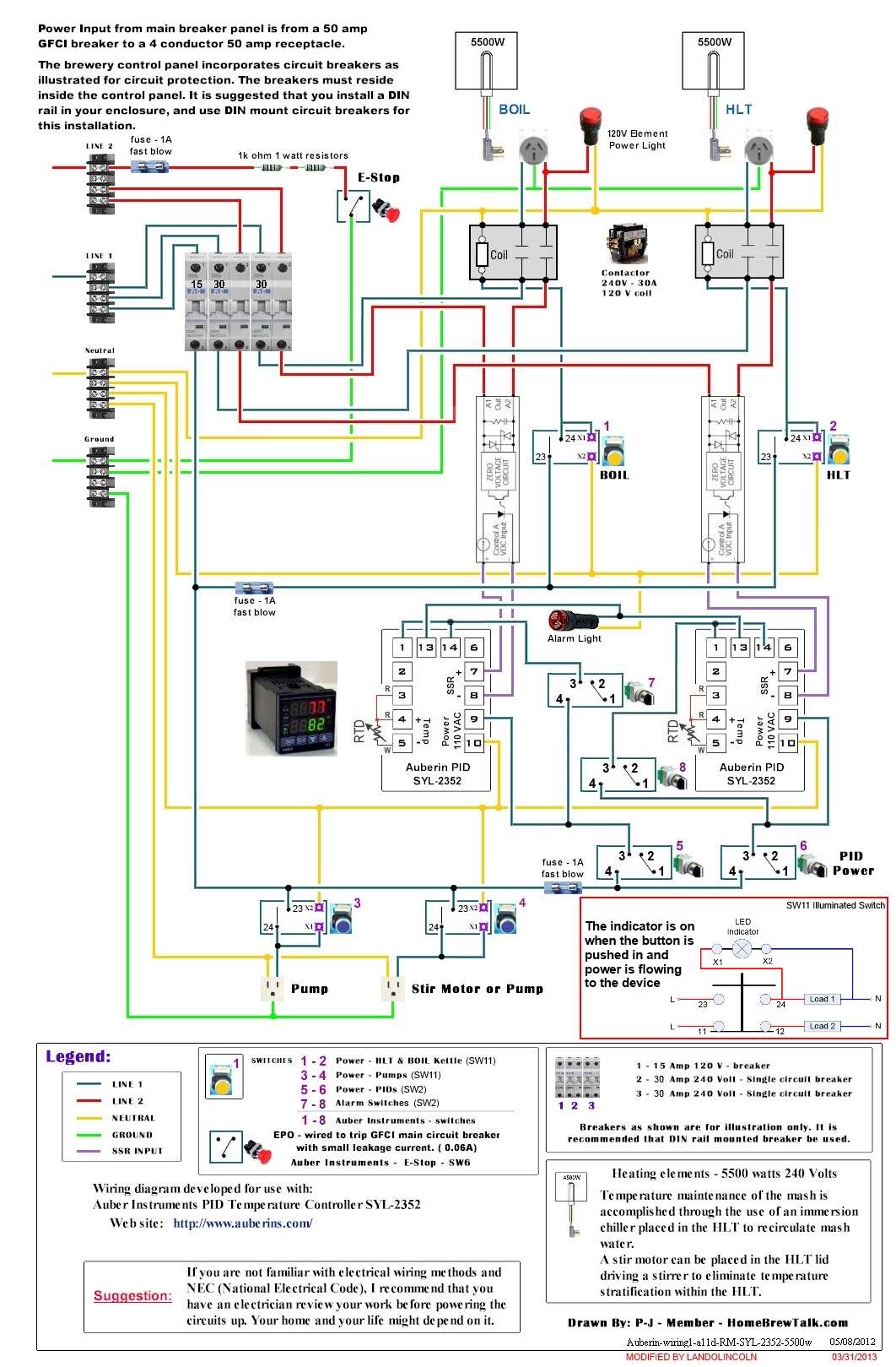
Link to the full-size drawing here in case the image doesn't show up
I just want to make sure that I didn't change anything to make it unsafe or unworkable.
Original drawing name: Auberin-wiring1-a11d-RM-SYL-2352-5500w dated 05/08/2012.
Original thread here
Changes made to the original drawing:
* 25a DIN-mounted breakers changed to 30a
* 240v element power lights changed to 120v
* SW1 switches changed to SW11 switches
* Added an SW2 switch to the HLT side of the alarm setup, so there would be individual off/on switches for each PID
* Changed the numbers of the SW2 switch connections
* Designated the 1A fuse going to the E-stop as "fast blow"
* Swapped the boil kettle stuff to the left and the HLT stuff to the right (no biggie)
* Changed the color of the illuminated switches (big freaking deal, I know)
And that's it.
I am also planning on adding two RTD temperature displays, one for the MLT and one for the chiller. I'm planning on adding these to the circuit that is powering the PIDs. There won't be any switches for them. I don't think that there is much chance of them overloading that circuit.
And I'm going to be installing float switches in the positive side of SSR circuits (between the PIDs and SSRs) to stop the SSRs from firing if the float switches say that there's not enough liquids in the kettle or HLT.
So please let me know if I'm doing anything wrong with this. Thanks!
Link to the full-size drawing here in case the image doesn't show up
