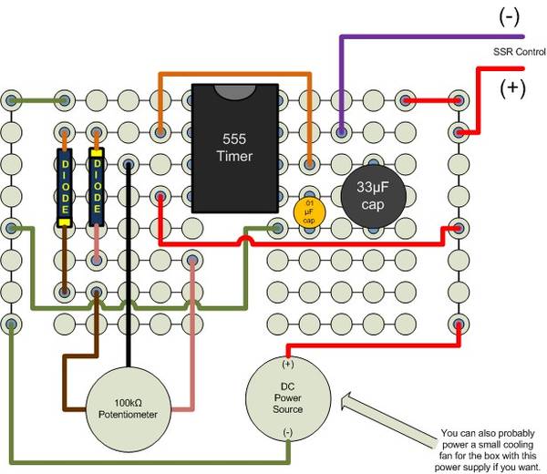
"C1 is between the ground post and the Pot! C2 is next to the 555 Chip"
I think you need to mind the polarity of the replacement cap if it's an electrolytic.
I think you need to mind the polarity of the replacement cap if it's an electrolytic.

barleywine!

I've seen the same circuit other places. The cost is still about the same though.
I'm currently (kinda) working on building them at home by buying lots of components cheap on ebay and etching my own boards. Reminds me I need to try the layout transfer again tonight after racking my barleywine into secondary. Actually, I think the Christmas Ale is ready for secondary (keg) too. Also reminds me I wanted to grab a piece of aluminum for pressing the transfer. Gotta run out back. See ya!
Homer: have you looked at mouser.com for ordering parts? I can't imagine things being too much cheaper on ebay than from mouser. 555 timers are like $0.18, diodes are $0.09, resistors and capacitors are a couple of pennies.
Here's the total bill of components for the PWMs like I have built , $2.05 per build.
http://www.mouser.com:80/ProjectManager/ProjectDetail.aspx?AccessID=42dabdadd1
Save me one. The one you gave me at Yoopers brewday was awesome
If you, or anybody on here for that matter, are building these to sell I would be interested in buying one. I don't have any experience when it comes to soldering circuit boards and I would feel a lot more comfortable with somebody else doing it.
")
Walker, which schematic is the one that will work with the parts you listed for mouser? I'm really keen on making one now that a parts list is readily available. Maybe even two!

...
The parts list I gave is not 100% complete in the sense that it does not include a board to put all of the parts on. ...
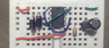
But that honestly was a bit of a pain. Tiny connections and wires. I have built several more since then, and I went the cheater route and used asolderless breadboard to assemble them, which is really handy. (If that link is dead, just search ebay for "solderless breadboard" and you will find more.)
) that I could use for testing.Homer: I considered making and selling them too but I don't think it would be possible to cover the vendor fees with a small margin on a PWM.
... Here's the total bill of components for the PWMs like I have built , $2.05 per build.
http://www.mouser.com:80/ProjectManager/ProjectDetail.aspx?AccessID=42dabdadd1
... But that honestly was a bit of a pain. Tiny connections and wires. I have built several more since then, and I went the cheater route and used asolderless breadboard to assemble them, which is really handy. (If that link is dead, just search ebay for "solderless breadboard" and you will find more.)
Just because it makes more sense with shipping.This definitely seems more up my alley since there is no soldering to be done.

Just to make sure I understand this right, if I order Walker's project from Mouser and a solderless breadboard, that is all I need to build this board? After that, all I would need is a DC power source and SSR and that would control the heating element?

Well.... there is still some soldering. The potentiometer looks sort of like this:
...
So you need to solder wires onto those little lugs. (And actually.... the pot on my parts list has FIVE lugs... two of them act as a power switch, but you don't need to use that).
The solderless breadboard, the components on that mouser 'project' I linked to, a DC power supply, and an SSR. Those things gives you the ability to adjust the amount of on/off time of a heating element.
There's a lot more to complete a full project: a box to put it all in, power cables, heating element, mounting kit for an element, etc, etc.... but the board, mouser components, SSR and DC power are all you need to build a basic control circuit.
One bit of advice.I can handle that soldering, it's the soldering on circuit boards I seem to fail at.
I've been trying to figure out how I want my setup since my situation is a little unique. We just moved into a new house in October and I want to make the switch to electric but don't have the funds to go all out right now, that is why I am trying to go as simple as I can right now and then slowly gather the parts to go all out. I plan on using the spa panel from HD to house all the electronics, a 5500w element from HD as well and getting my power from a stove outlet.
I pretty much have everything figured out. Controlling the element was the biggest hurdle, but that's no longer a problem.
BTW, those faucets and shanks you sold me are still working great!
One bit of advice.
Before you go ordering anything from mouser.com...
A couple other things I think you will want to add to your system:
- a manual "kill" switch to absolutely positively kill the power to your heating element.
- a small fan to blow air around and keep the SSR cool. They tend to generate a lot of heat.
- some thermal grease to put between the SSR and it's heatsink (helps transfer heat)
- small panel mount circuit breakers to drop that 50A service you have down to 25A or 30A (whatever your heating element needs).
Thanks Walker that diagram is what I'll be using to use the potentiometer to control the power completely. Might as well, right?
I was going to put on here that you could use a 555 ic as an oscillator with a pot to skew the duty cycle and make your own PWM but after looking at how cheap those bakatronics PWM controllers are I say that is gold.
Clem
To make the math easier, assume you tried a 60Hz frequency for the PWM.
Like you said, there are 120 zero-crossings per second with an AC SSR. But in terms of zero crossings per PWM cycle you only see two crossings.
A 60Hz PWM would only be able to hit 3 settings: 0%, 50%, or 100%. No finer granularity would be possible.
And don't forget that the PWM does not switch instantaneously. I think the one I use has a 25ms switching time. If you cycle the PWM too fast the SSR will never even be able to actually switch on and pass current through.
Walker said:what schematic are you using? You can probably use the smaller pot if you use a smaller controlling capacitor.
I used the 3 component schematic. With the 2.2 cap
Walker said:If the pot you have available is 1/5th the size as the one in the schematic, then you can probably just use a capacitor that is 5 times the size of the one in the schematic and maintain the same timing behavior.
So... 11uF in this case.
But, you could even go larger and still get a reasonable frequency for the PWM. If I am reading/understanding it right, the circuit with the 2.2uF cap and the 500kOhm pot is actually cycling a little too fast (about 1.3Hz).
If I am correct on my calculations, I'd probably throw a 22uF cap in that with the 100KOhm pot and get a frequency of 0.65Hz.

Enter your email address to join: