Very true our motors with gearbox are almost the same. Another thing these are not cheap items and the inside of these worm drive gearboxes are very high quality with preloaded tapered bearings. All iron for a even rate of expansion allowing for a constant bearing preload. My Baldor/Precision Gear unit has the worm ground and hardened into the motors shaft hence a special built motor thru Baldor as I went thru many tech people before I got the starter and capacitor specs for it then figured out how to wire it. I will have it so that it can run both directions to get my nose out of the mill or what else it might eat besides grain. My unit came off a disability ramp chair that had a rack the output pinion powered.
Many units are 24 volt powered with 30 amp DC motors, that's a 1 hp motor at 1750 rpm's with app a 8:1 serptine belt 3/4" wide into a 40:1 gearbox for 5.5 rpm's. This is a great Gearbox output unit with a 7" diameter cast iron hub on a 2" shaft that held 55' of 3/16" 7x19 aircraft cable. We used this setup on the dock and lifted a 24' 350 chebbie boat anchor powered stern drive boat with two 4" wide cargo slings. This must of been a 3,400 pound boat without this unit knowing it had a load on the gearbox.
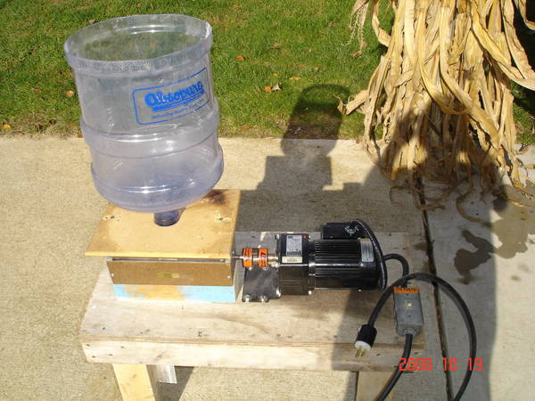
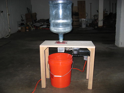
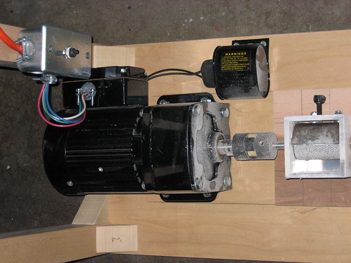
My 1/3 hp Baldor with Precision Gear gearbox is rated at .48 hp input at 1750 motor speed. I have 1/3 hp at 1725 rpm's. The output off the gearbox is 7/8" shaft rated at 565 inch / lbs at 28.75 RPM's. I plan on adding a 1/2" diameter jackshaft 4-5 inches away and back over the top of the gearbox supported with two 1/2" ID pillow block bearings. This will allow me to gear up by 3.111 ratio with #40 sprockets 28 to 9 tooth as stated above only 5" between shafts for my 89 rpm's at the mill. The other end of the jackshaft that will be app 6" long will have a LoveJoy to direct drive the mill. I will use airbalancer's design (thanks bro) for a hopper, sorry i'm stealing your design but like it. I'm thinking smooth white plastic off a disability elevator wall material with thin angle aluminum for the frames exterior. Still all in the design stage while on the mend.
On to my main topic at hand;
My MM3-2.0 is a mess, new in box from Fred. Sorry Fred I do not believe the bushings "can pop out on their own while in shipping", this bushing is out of one of the stainless gap adjusters and sticking out beyond the end of the stainless adjuster by 0.084". This besides the other bushings sticking out of the end frames inboard towards the rollers direction by plus; 0.007", plus 0.008" on the end of the stainless adjusting knob body as well add 0.003" more for the bushing plus the 1/2" input drive bushing at a plus 0.015". All on one plate into the rollers.
The other end plate has one bushing at plus 0.010", one at plus 0.018" and the stainless adjusting knob body in at 0.008" with the bushing sticking out an additionally another 0.084" more into the rollers.
Yes told "tested and gap clearances adjusted and set at the shop on every mill before shipping them out". My end plates are scared up from the sharp edges of the rollers on both end frames also due to the bushing twisting the end frames out of square. I have a question on how the hell can this mill of been "assembled and tested before leaving the manufacture" with these problems with my mill? Bushings back out during shipping I call B/S on that answer.
I was told since my background was a licensed A&P mechanic I should be able to handle a simple bushing and mill vs what I have worked with in the past and this includes a machine shop. Hell I have a Bridgeport mill in my home shop. What if I was a regular homebrewer wanting my own grain mill and ended up with this mill?
I have measurements and pictures in my digital camera but can not post directly to this forum as I can not post as I am not a paid up member. I was once called "only a visitor on this forum" hence why not in any hurry at all to join.
Not a happy camper for this $246 mill. Another thing the 3/8" journals as well the 1/2" drive journal at the bushing contact areas need polishing as they are rough and will eat away at those bushings. They need to be polished smooth as they are yellow with bushing material embedded into the journals. If your a new owner of one I would check, polish and debur everything and set the bushing to the proper heights before you can assemble and use this mill. It is not a cheap investment. Set up properly you should increase the bushings life by many times as oillite bushings will wear away long before those rough finished 1144 steel journals. JMO's if I were you.
With the roller axle diameters at .368, .368, .370, .368, .367 and the drive at .495" with the end plate bushings on the 3/8" at .373" and the drive bushing at .498", I have .003" on the drive input shaft clearance. On the 3/8" shafts the clearances range from 0.003" to 0.006" clearance or looseness. I would rather have the journals polished smooth as well the sharp chamfered edges of the rollers smoothed down vs wearing away the bushings and scoring up the end plates more that what damage has already been done with my end plates by these rollers with sharp burs. Details make a difference.
Sorry I had to let others know that these mills need to be looked at before building your MM grain crusher if you want it to have a long wearing bushing life. I have a end gap between the rollers of 0.092" due to one bushing sticking out into one roller causing the end frame to stick out causing all rollers to have this extra end clearance of the end plate by 0.092". Not what I would call a functional mill. I will correct these problems plus add a aluminum plates with a window for grain in for the top and one for the bottom both bolted to the mill directly. This will maintain a solid frame to keep the mills end plates square as well the end clearances of the rollers set without the end frames spreading apart, moving around and flexing out of square. This will greatly increase the life of the bushings plus preventing binding of the bushings. Wear in or wear out in this case is not the proper answer. The bottom end frame plate will be made wider than the mill to attach the mill to a table or other mounting object so the mill can be mounted solid. All in the future repair and planning stages. I was told the bushings are made to stick in past the end frame plates to keep a clearance between the rollers from rubbing on the end plates. The edge surface area of these thin bushings is rather small vs if flanged bushings were used and pressed into counterbored frame end plates this allowing for a larger surface area for the rollers to rub against as well machined to allow for the bushings to stick inside the end frames keeping the rollers away from the aluminum end frames. Something like 0.006" of a flanged bushing sticking above the end frame surface would be plenty of clearance to keep the rollers from chewing into the end frames. Mashing with aluminum particles is not my desire.
Think why not use flanged sealed ball bearings instead of bushings all together not shielded bearing but sealed to keep dust, dirt, grit, grain and flour out of the ball bearings. Then this woild be a lifetime mill. JMO's here.
Done ranting and venting I just had to speak up after thinking about this mill since delivery 5 days ago and yes I have sent Fred emails as well pictures of the end plates and the bushing sticking out of the stainless gap adjuster.