ASL-51 timer wiring

Homebrew Talk - Beer, Wine, Mead, & Cider Brewing Discussion Forum

Help Support Homebrew Talk - Beer, Wine, Mead, & Cider Brewing Discussion Forum:

This site may earn a commission from merchant affiliate links, including eBay, Amazon, and others.

rgrrbt

Member
Joined
Sep 28, 2010
Messages
18
Reaction score
11
I've been following Kal's great plans over at theelectricbrewery.com, and am in the process of wiring my control panel.

I am using an Auberins ASL-51 timer, and after reading the terminal assignments in the manual and attempting to compare it to the diagram in the instruction manual for the Omega PTC-21 that Kal is using, I am not certain as to how to wire this to meet my goal.

The goal in wiring the timer is to have a normally open contact block connected to a reset button that would start the timer countdown over. I also have alarm switches for each PID and the timer itself. The idea is to wire this to have the same results as outlined on Kal's build here.

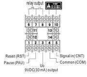
Here is the terminal assignment diagram for the ASL-51:


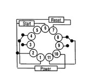
Here is the diagram for the PTC-21:


How can I translate Kal's wiring for the PTC-21 to the ASL-51?

Thank you in advance.

Rob
 
I did the same thing....and I bounced a few versions off Kal as well.

Here is my bastardization of Kal's timer wiring sheet.
This works just as his design does which makes me happy!

Hope it helps :mug:

timerwire.jpg
 
That reminds me.... I need to post this on the site! THanks for doing this Jay!

Kal
 
What programming mode did you select. I was thinking
Code 4: Time delayed on or off (cnt down) - 1M-9999M
Relay 2: Starts counting by reset. Relay pulls-in when reaches the set value.
 
Don't have the page with the codes here to tell you exact...

But I definitely used Relay 2 to have it start countdown by reset

I toyed with the 1-9999M one but ended up using the 1s-99m99s one cause I like to see the seconds ticking off :)

While there may be occasions where I'll be boiling for longer than 1.5 hrs (120 IPA comes to mind)...odds are it will be broken up with hop additions so it won't be counting down the whole time, just 10-15m breaks


And I like seeing the seconds tick off :)

I'm in the same boat as you are using this timer...it takes some getting used to, that's for sure. But I can't get the alarm to work! Nothing will trip it, not the PID's or the timer. I swapped out the buzzer for a lamp that I know works....still nothing.

I wired #13 to the hot bus....but i can't understand why you also used a jumper from #1 to #14? If you only use the NO relay ALM 1 it shouldn't matter, right? Maybe I'm being stubborn, but I can't see WHY it was wired this way; so I wired it the way I thought it should work....and it doesn't work :eek:
 
The PID wiring I got off Kal's site...the only thing I added was the timer wiring.

I haven't tried the alarms off the PIDs but I know the timer one works.


In my totally un-electrical vocabulary the way I see it is:

The neutral side of the horn is always complete.
The hot side is only completed when a few things align
1) a device trips the connection (being the timer expires or the pid does its thing)
AND
2) said device's switch is in the ON spot

Now granted if more than one switch is ON I won't know which is causing the alarm at first glance...but I can fix that issue by training myself to always keep them OFF unless I want it to ring.

That make any sense?
 
I'm defintely an electrical noob, but am learning a lot from lurking around here and Kal's site. I too have the ASL-51 and am following the schematic posted here. Question I have is on Kal's diagram #3 terminal from the reset switch goes to neutral bus, but on the diagram here it does not. Am I correct in assuming that there should be a hot black wire to the #1 terminal on the ASL-51 and no white wire coming off the #3 terminal from the switch to the neutral bus, or should I still wire to the neutral bus AND the terminal on the timer?? Thanks.
 
i wired it as diagramed and it seems to work. I just finished running my power today to my garage today, so I have not programed it yet, but it comes on and the rest worked.

10 from the pid is the netural, which you are jumping to terminal 9, then on to the light and alarm. The timer is switching the hot to the light and alarm on 7. Hot is powering the switch on 10, and jumped to 8 to feed power to 7 for the light and alarm? Does this make sense?
 
oh for 1 and 4, think you can use any cable size. It is just completing a relay to tell timer to reset. I think i used 14 gauge white wire. 3 is a dc out, you do not need that. 4 is a common for the pause and reset. think of it as a hot, this runs to the push button switch. When you push the button, it sends the current to 1, which tells the timer to reset
 
I did the same thing....and I bounced a few versions off Kal as well.

Here is my bastardization of Kal's timer wiring sheet.
This works just as his design does which makes me happy!

Hope it helps :mug:

timerwire.jpg
Jay, can you repost the image, the link is down.

Thanks!
 
Actually for the current in the circuit you could use speaker wire but I would go with something a little more substantial. Use your discretion.
 
I know this thread is a little old, but it's really close to my question. I bought the asl 52 timer. It has 12v inputs. I don't have a problem getting 12v to the timer. My question is do I run a 120v hot to the relay output? That is what makes sense to me. The terminals are the same as the asl 51 exept 9 & 10 call for low voltage.
 
bosipipes said:
In your Diagram you have a purple wire going to the reset button.
I dont see any wire going back to the neutral buss. is that right?

Diagram is correct. The reset is a dc circuit I think, just tells the timer to reset when closed or open, forget which one.
 
Can someone repost this diagram? I can't get the picture to get any bigger than a postage stamp.
 
I need a little help. I bought a ASL-51 timer and TA-4 PIDs and don't feel confident I have them wired right. I've attached the TA-4 Timer pin out, ASL-51 PID, and my DRAFT schematic.

Any help will be great. Thanks.

ASL-51 Timer.jpg


TA-4.jpeg


TA4_ASL51 Schematic.jpg
 

Latest posts

Back
Top