blackheart
Well-Known Member
I am working on building an automated brewing system. This consists of multiple 120 and 24v AC pumps and valves. I have a prototype built and working but its time to move on to a solid and robust design.
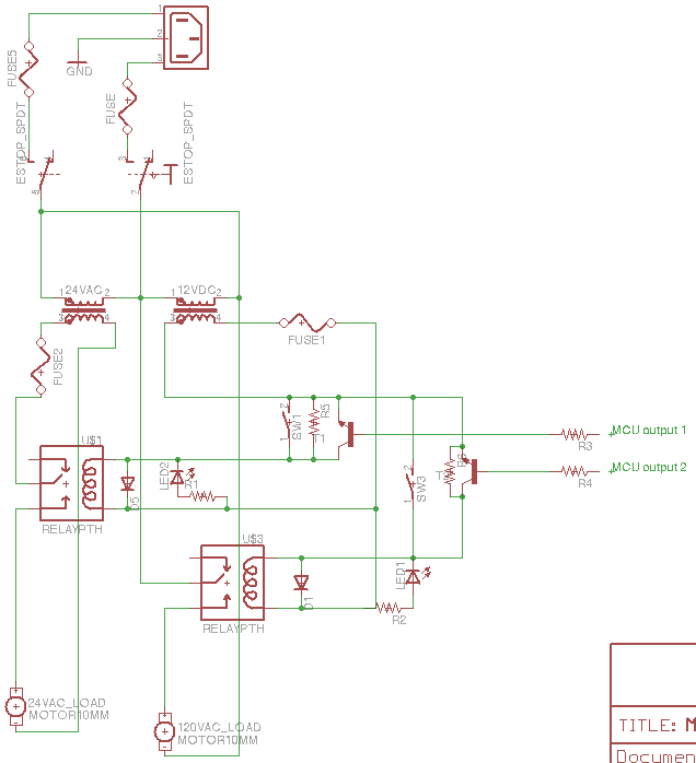
I have drawn a basic circuit diagram showing the flow of both 120v AC and 24v AC through the system to power two loads via relays. The relays can be triggered by either a manual switch, or, a transistor via a micro controller. The relays are ground triggered and I have added a diode to protect the transistor/microcontroller in the case that the manual switch is flipped, no current will get back to the microcontrollers inputs.
I have also added a diode over the relay coil so when the magnetic field collapses everything is protected. There are fuses at numerous points throughout the circuit to protect the various parts. The picture of the 12v DC coil is ment to represent a 12v DC power supply, which would be a separate product.
To operate the circuit, you would turn on both the E-stop switch and power switch. Pressing either switch connected to a relay will both trigger that relay and send voltage to the load connected to it. It will also light a LED to signal that it has been activated. Alternately, the microcontroller could send a 5v signal to the transistor to trigger the relay.
My questions are the following
1) Does this circuit design look safe to you?
2) Have I placed fuses in the appropriate locations?
3) Have I protected my relays, and microcontrollers with diodes correctly?
Currently I have something very similar to this design up and running, however it has no fuses or diodes, and I have not tested the microcontrollers ability to control it due to safety concerns for the MC. Thanks for your help!
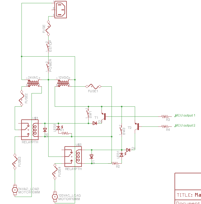