• Please visit and share your knowledge at our sister communities:
  • If you have not, please join our official Homebrewing Facebook Group!

    Homebrewing Facebook Group

Question on wiring/setup for 2-stage Inkbird in Collar

Homebrew Talk

Help Support Homebrew Talk:

This site may earn a commission from merchant affiliate links, including eBay, Amazon, and others.

UT-Alex

Member
Joined
Jun 16, 2015
Messages
21
Reaction score
1
I'm not sure if this is the right area or if it's more of an electrical area.

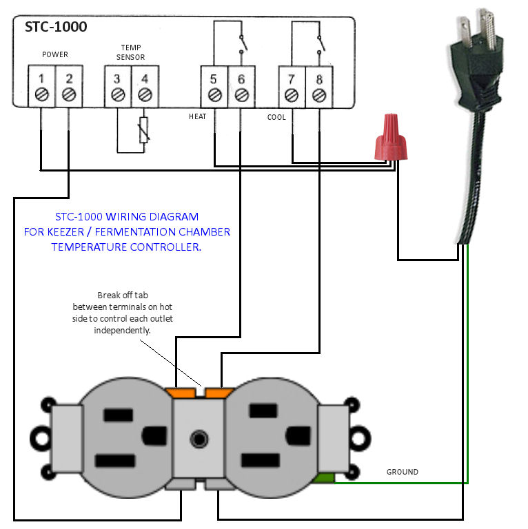
I'm in beginning of a keezer build and I've decided I'd like to do some more DIY work with the temp. controller and I'd like to have this knockoff STC-1000 in the collar mostly for aesthetics and I like the idea of having it within the keezer versus a separate project box.

So question 1: Does anyone have anything negative to say about the 2-stage Inkbird controller? I plan to use this keezer as a fermentation chamber as well and the main reason I am wanting to purchase the Inkbird over the STC-1000 is the Fahrenheit display.

Question 2: I'm not super handy with electrical work, so I was wondering if 2 electrical outlets are required for a 2 stage? I've seen a lot of project boxes with 2 electrical outlets like this.

I understand I'll need a heater inside of the keezer to kick on and I'm trying to figure the best set up for this. Here's what I currently have in mind:
image.jpg


Can I plug the heater into the same outlet or will I need 2 electrical outlets and have a cord running back in through the collar to the heater?

The inside should look like this. And the back should look like this but potentially 2 electrical outlets? That's my main question.
 
Most 15amp outlets have a break off tab on the hot side that allows you to wire 2 separate circuits - one on each plug - but share a common neutral and ground.
View attachment 286331

I'm a complete novice at this. I'm sure it'll make more sense once I get the Inkbird in hand along with the rest of the items. But what is the point of having two electrical outlets like this?

P1010024.jpg


Will I be able to heat and cool with just one outlet? And I should be able to wire in a PC fan to the power without having to worry about an additional outlet, right?
 
The diagram posted above, will basically give you "2 outlets", versus "physically" having 2 "separate" outlets.

1 heat, and one cool.

To your question @ the bottom, Yes on the one outlet, and find a place to wire in the PC fan, if you want it to run all the time.
If it were me, I would run the PC fan whilst in the cooling mode only...........This, depending on what your mode of heat will , conduction or convection.

So I should be able to accomplish everything I need with one standard outlet if I'm understanding you correctly. The top portion of the outlet can be for the freezer to plug into and the bottom portion can be where the heater plugs into? This is easier than I thought it would be.
 
I used the Love controller but they work the same way. I wired mine like the graphic I attached. I use an adapter to include a fan on the cool side. It's very seldom my hot garage will need a heater but I'm wired for it for those rare occasions.View attachment 286343

Awesome, I didn't even consider doing it like this but I think that is probably the better option. Thanks man!
 
Just going to leave this here in case someone has a similar question in the future. Now to figure out my best way to prevent cold air loss from the hole in the collar.

AaEi8qD.jpg
 
I have had the Inkbird controller for a couple months now (since they started advertising on HBT) and have zero complaints. Just like you I wanted the ease of seeing Fahrenheit versus having to convert. Works just like any normal STC just in Fahrenheit.

As far as preventing cold air loss from having the controller in the collar you could try Great Stuff. It's a spray foam insulation so all you need to do is mount the controller in the collar and then spray the Great Stuff around it. A little goes a long way as it expands pretty quickly and should form a decent seal.

I'll look into that, thanks for the tip!
 
Can someone check my wiring on this?

KB_Wire_Detail.jpg

The red is live, neutral is gray and ground is green. Maybe I'm not using those terms correctly because the confusing part to me is there isn't a red going to the outlet that will be mounted on the collar.
 
This is not right. I am not qualified to tell you exactly how to wire it but this isn't it. You are going to want #6 going to one of the hot terminals on the right side of your outlet diagram and the #8 going to the other hot terminal on the right. Your controller is giving power to only one of those at a time and that is how your load (either cool or heat) gets energized.
 
Your power from the wall needs to run directly to the controller. Then you will run power from the controller to each of the outlets, one for heat and one for cooling. Doesn't that controller come with a diagram?

Look for one of the STC-1000 build threads on here. That should give you a better idea of how to wire this one up.

I found this diagram that might help.

temp-controller-wiring-diagram.jpg
 
That diagram still doesn't look right to me. I'm thinking the lines from 6 and 8 are hot and correct but then this has the hot from the wall plug tied to neutrals 5 and 7. I think 5 and 7 should be jumpered with 2.
 
That diagram still doesn't look right to me. I'm thinking the lines from 6 and 8 are hot and correct but then this has the hot from the wall plug tied to neutrals 5 and 7. I think 5 and 7 should be jumpered with 2.

I thought the same thing when i first wired mine, but 5 and 7 are the hots coming in from the wall. 6 and 8 are switched by the controller to turn on heat and cooling. The neutral goes to the outlet and then ties into the controller.

5 and 6 are the switch for heat

7 and 8 are the switch for cooling.
 
That diagram still doesn't look right to me. I'm thinking the lines from 6 and 8 are hot and correct but then this has the hot from the wall plug tied to neutrals 5 and 7. I think 5 and 7 should be jumpered with 2.

The only neutral connections are to the bridged terminals at the duplex outlet and pin 2 at the controller.

5 and 7 are always hot. 6 and 8 are the corresponding "switched hot" terminals...

Cheers!
 
I think what has been confusing me from the manufacturing diagram is that 2, 5, and 7 are all tied in but I may just be reading that wrong because it doesn't consider an outlet in the diagram such as the one above.
20150203202601_12623.jpg


I made some adjustments thanks to everyone's input. This should be the final diagram if I understood everything correctly.
vOr60pX.jpg


It's a bit unfortunate that my temperature controller is far from the outlet which isn't the case for people who mount both in a project box. I was trying to keep all of these cords coming from the controller in the extension cord sheath but it looks like everything needs to be wired directly.

After a bit of searching I think I can group all the cords together in this plastic conduit and it should help group and protect them all.
newblackwireloompic.jpg
 
The confusion may be due to the fact that neutral is being switched in the suggested connection diagram.
20150203202601_12623.jpg


While it will electrically function, switching neutral is generally considered "less than optimal" (I'd call it utterly fubar myself) because it leaves an "always-hot" line at the load, as well as a ground return. Touch them both even while the switch is open and enjoy the tingle ;)

Cheers!
 
Can it be wired to switch the hot instead of the neutral?

Yes it can. Just take all of the blue wires and put them on terminal 1 and and make them the Hot (120v) wires and then take all of the Red wires and make them the neutral.

UT-Alex you still have your diagram wired wrong. You can't have the hot on terminals 5 & 7 and and the neutral on terminals 6 & 8. that will make a direct short. If you haven't turned the circuit on, don't! If you already have, I'm sure you know there is a problem somewhere. The 2 sets of terminals act like a switch with only the hot wire going across them. The pic TechyDork sent you is good and you should follow it. It is exactly what you want to do.

This is the way the Inkbird Schematic should be shown so as not to switch the neutrals.

InkBird Wiring.jpg
 
Last edited:
Yes it can. Just take all of the blue wires and put them on terminal 1 and and make them the Hot (120v) wires and then take all of the Red wires and make them the neutral.

UT-Alex you still have your diagram wired wrong. You can't have the hot on terminals 5 & 7 and and the neutral on terminals 6 & 8. that will make a direct short. If you haven't turned the circuit on, don't! If you already have, I'm sure you know there is a problem somewhere. The 2 sets of terminals act like a switch with only the hot wire going across them. The pic TechyDork sent you is good and you should follow it. It is exactly what you want to do.

This is the way the Inkbird Schematic should be shown so as not to switch the neutrals.

I was going to wire my unit today actually, but I'll hold off now that I'm confused. I based my new diagram off of the one TechyDork sent me. The lines follow from the same port on the controller to the same location on the outlet in both diagrams. Maybe this is easier than I think, are you saying lines 6 and 8 should be red as well and only 2 is gray?

Is there something about the composition of the gray wire that won't allow it to switch like the red wire? Sorry, my understanding about electrical stuff is very limited.

vOr60pX.jpg


temp-controller-wiring-diagram.jpg
 
UT-Alex I gave you some bad poop. I apologize for my mistake. I was just looking at the colors of the wires you had going across those contacts and in my mind the grey was the neutral. And no electricity doesn't know colors, so there is nothing in the composition to make it hot or neutral. It would be common practice to make 6 & 8 a red wire also and not the grey color you designated for the neutral. What you have drawn is good. Once again I'm sorry for the confusion.
 
UT-Alex I gave you some bad poop. I apologize for my mistake. I was just looking at the colors of the wires you had going across those contacts and in my mind the grey was the neutral. And no electricity doesn't know colors, so there is nothing in the composition to make it hot or neutral. It would be common practice to make 6 & 8 a red wire also and not the grey color you designated for the neutral. What you have drawn is good. Once again I'm sorry for the confusion.
Whew! I've been waiting for a response hoping this was the case. Thanks for the confirmation!
 
Thank You for showing the "Break Tab" as I have been dealing with endless cold until I saw that in your drawing. I must have seen 30 to 40 drawings as reference but never saw the "Break Tab" ...been dealing with excessive cooling randomly for over 3 weeks.

Thanks again,
Mike
 

Latest posts

Back
Top