motorized mill wiring

Homebrew Talk - Beer, Wine, Mead, & Cider Brewing Discussion Forum

Help Support Homebrew Talk - Beer, Wine, Mead, & Cider Brewing Discussion Forum:

This site may earn a commission from merchant affiliate links, including eBay, Amazon, and others.

SpaceCoastBrew

Well-Known Member
Joined
Nov 29, 2009
Messages
152
Reaction score
5
Location
Kentucky
I recently acquired a MM2-2.0 and a bodine gear motor for my direct drive milling station. I'm trying to keep this as simple and safe as possible. The gear motor is reversible so I was thinking of using a keyed fwd-off-rev switch like this one: GCX1470-22 Products and a mushroom style E-stop button.

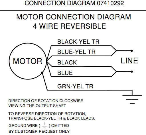
Is there any reason why this wouldn't work? And what would be the best way to wire this? Here's the motor wiring sheet:

motor%252520schematic.jpg
 
You need a DPDT switch to support forward/reverse. I bought a 10amp switch at Radio Shack for $4 to control my bodine gear motor.

A DPDT switch is two independent single pole switches in one, so you wire the forward speed to one side and reverse speed to the other. Very simple.

An e-stop may be overkill.
 
I just used a toggle switch. On off on wired like the above spartan post. I don't see a need for a DPDT
 
SpaceCoastBrew (Matt),

I was not able to pull up the specs on the motor but was able to get the diagram as you posted it. The pdf file that I found had a little more info but not all of it. I was looking for the HP and motor speed info.

Try this wiring plan:

motor-schematic.jpg

____________________________

You would be wiring the key switch using N/O modules only. You will need to secure a second N/O module. Perhaps you can get Automation Direct to exchange the N/C module that would normally ship. I'd suggest that you call them.

I hope this helps you.

BTW, I did not set it up with an e-stop. To do that, you would need to have a GFCI breaker in the power source setup. Simply turning the motor off will do the job very well IMHO.

P-J

Edit: After looking at the drawings again, I discovered that the switch I placed in the drawing did not shut the motor off. My bad, I modified the drawing to incorporate additional N/O modules so that the power would be shut off when the switch is placed in the center position.
 
P-J,
Thanks, that helps a lot! To clarify, would my neutral go the blue-yellow lead? That was exactly my plan on the NO blocks, AD is really good to work with so hopefully it won't be an issue to get those switched out. The e-stop is easy enough to wire and under normal circumstances won't ever be used but I work around industrial systems and I've seen people panic. A big red button just makes things easier in those instances.

Here are the specs on that motor: Bodine 42R-5L

Thanks!
 
Ok... I modified the diagram to show a little more info including the E-Stop:

motor-schematic-3.jpg

____________________________

I hope it helps.

P-J

Edit: After looking at the drawings again, I discovered that the switch I placed in the drawing did not shut the motor off. My bad, I modified the drawing to incorporate additional N/O modules so that the power would be shut off when the switch is placed in the center position.
 
P-J, that's EXACTLY what I was looking to do. I understand the theory but suck at the application part of it. Thanks for the diagram and your help! :mug:
 
This is off topic, but what really bothers me about this site.

You get two accurate technical suggestions and two inaccurate suggestions, of course both claiming to be correct. Which, makes it difficult for the OP to get a clear answer.
 
This is off topic, but what really bothers me about this site.

You get two accurate technical suggestions and two inaccurate suggestions, of course both claiming to be correct. Which, makes it difficult for the OP to get a clear answer.
Not the least off topic, IMHO, but right on the money. Your initial post to the question was also spot on.

The OP & I communicated via PM so that I had a good understanding of the issues AND the motor involved. I omitted the E-Stop in the first drawing & then learned that it was very important to Matt. That's why I made the second drawing. (I also wanted to show the progress within the thread so I retained the inital drawing for all to see.)

For the most part, I will not make a diagram unless I have a clear understanding of the mission and the devices involved.

I appreciate your post very much as it is really spot on. A lot of folks post info without really reading the Q or understanding the issues.

Thanks.

P-J
 
I appreciate your post very much as it is really spot on. A lot of folks post info without really reading the Q or understanding the issues.

Ya, I suppose I've become jaded over the years (way too many folks shooting from the hip).

Keep up the positive outlook, P-J. :)
 
P-J, you are extremely helpful. I have a very basic understanding of electrical. Is there any chance you would run through the diagram w/o the safety stop and just explain in laymans terms how that wiring setup works? if it's too complicated or time consuming, I'll understand, but if not I'm about to wire up my own mill and I'd really like to understand what I'm doing and why rather than just following steps. Thanks for any help you can offer
 
This is off topic, but what really bothers me about this site.

You get two accurate technical suggestions and two inaccurate suggestions, of course both claiming to be correct. Which, makes it difficult for the OP to get a clear answer.

In the OP post he stated he wanted to keep it simple. The simple way is to use a SPDT On-Off-On switch. Shown in the other example. If you don't use a capacitor you ignore that but the wiring is the same. So center position on toggle switch is off. Flip it one direction for FWD back to Off and the other direction for reverse. Not wrong, simple and cheap.
 
P-J, you are extremely helpful. I have a very basic understanding of electrical. Is there any chance you would run through the diagram w/o the safety stop and just explain in laymans terms how that wiring setup works? if it's too complicated or time consuming, I'll understand, but if not I'm about to wire up my own mill and I'd really like to understand what I'm doing and why rather than just following steps. Thanks for any help you can offer
After reading your post and question, I went back and reviewed the drawings and discovered that the power would not be completely shut off to the motor with the way I had drawn it. I've since modified the drawings to incorporate additional N/O modules so that when the switch is in the center off position, power will be shut down.

My bad. The switch is now a 3 pole - double throw - center off switch.
 
Back
Top