Looking to convert

Homebrew Talk - Beer, Wine, Mead, & Cider Brewing Discussion Forum

Help Support Homebrew Talk - Beer, Wine, Mead, & Cider Brewing Discussion Forum:

This site may earn a commission from merchant affiliate links, including eBay, Amazon, and others.

bpaulik

Well-Known Member
Joined
Dec 1, 2014
Messages
46
Reaction score
15
Location
Hedgesville
Hello,

I am looking for some advice, insight, and just some general input. I currently have a direct fire system that I want to convert to electric. I have a 15 gallon HLT, 20 gallon MT and a 20 gallon Boil Kettle. I would like to have the capability to do back to back brews although not a deal breaker if I can’t. I was thinking of using a single 4500 to 5500 Watt element for the HLT and Boil Kettle each, a 2000 watt element for a RIMS tube, and two pumps. I believe I would only need to run two elements at a time so I think I could do this with a single 50 amp circuit. Would anyone have any recommendations from your personal experience? I was hoping someone may have an electrical drawing for a panel using PID’s. I have seen some drawings on here from Doug293cz that look absolutely amazing. I love the safety feature that he adds in that it won’t allow the elements to be turned on without the pump being on.
 
I do single infusions, so I can make my system work with just a BK and a MT. I heat the water in the BK, pump over to the MT (underletting the grain), then recirculate through the RIMS tube and MT using the same pump. Then I just switch the line over from returning to the RIMS to the BK, and fill that up.

I can make it work using only one pump. If you feel you need the HLT, then you'll need the two elements (and BTW, use the 5500, no need to go low).

I'm never running multiple elements at once, though on my system I could if I wanted.

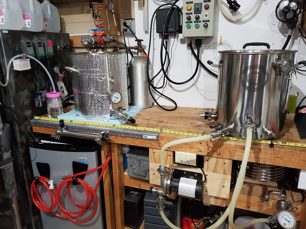
Here are a couple pics showing the setup. The first pic shows me recirculating through the counterflow chiller below the BK; when my strike water is right, I just close the ball valve that is in the middle of the kettle and move that hose over to the sight glass on the MT you see on the left, and pump that water in.

brewsetup.jpg


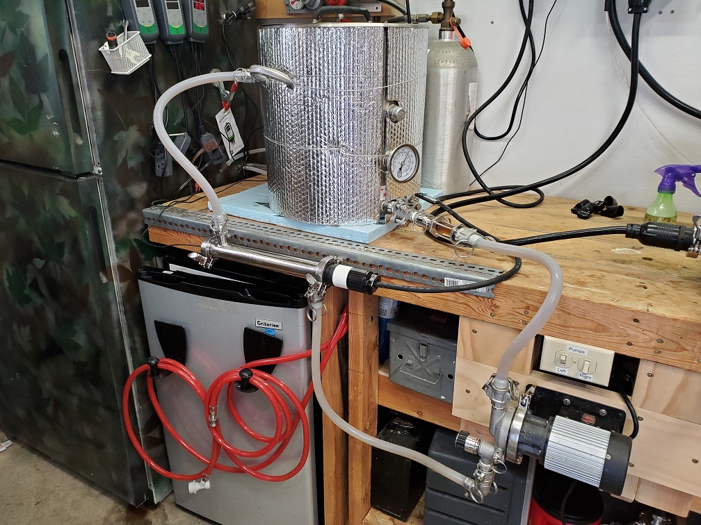
Same pump, recirculating through the RIMS tube.
brewsetuphosesRIMS.jpg


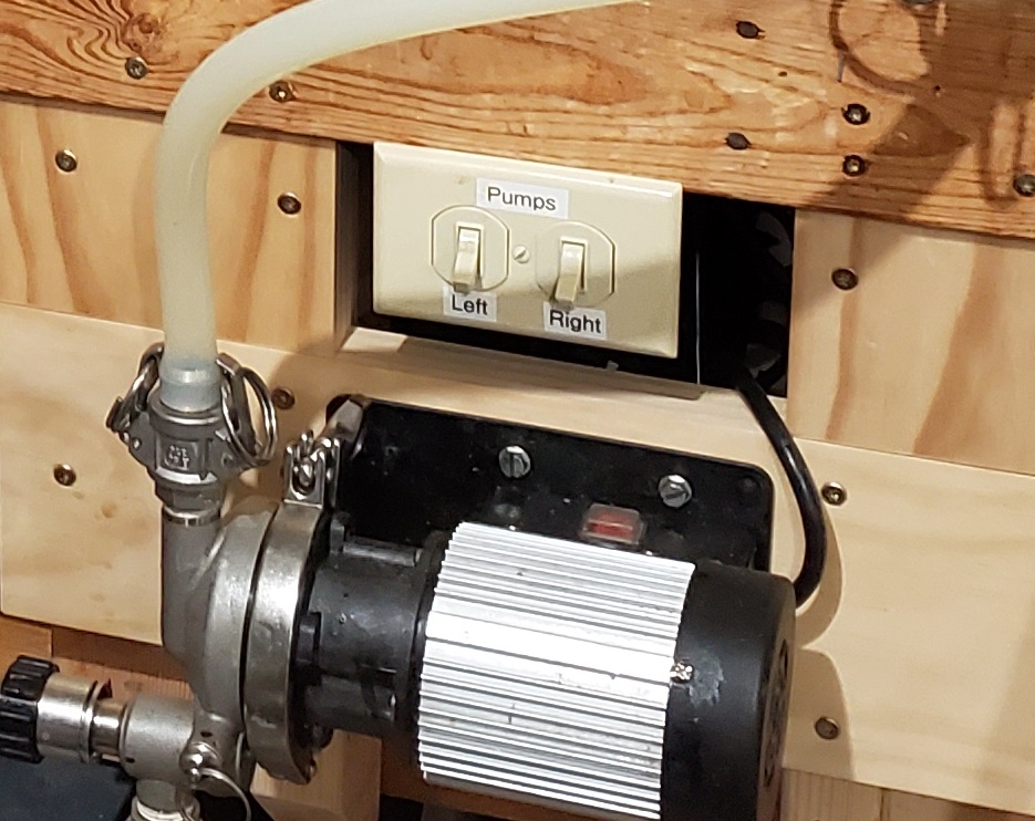
Third pic is showing the pump switches. I added an outlet under the bench (plugged into the GFI above) and switches to control my two pumps. Easier and more convenient than using the pushbutton switches on the control panel. The left switch controls the RIPTIDE; the right switch controls another pump I use to recirculate cleaning solution through the CIP ball on m conical.
brewsetuppumpswitches.jpg
 
I looked to see if I had any three element controller schematics, but haven't done one of those yet. A 2 x 4500W + 2000W panel for a 50A service would be relatively straight forward. But a 2 x 5500W + 2000W with only 50A available would require interlocks so that only two elements could operate at once. Have to spend some time figuring how to do that interlock with the minimum number of switches/contactors/relays. Since I would like the design to be of interest to the largest number of potential users, I'd like some idea of the interest in the 2 x 4500 + 2000 vs. 2 x 5500 + 2000 options. The panel for the higher power option will necessarily be somewhat more expensive than the lower power version due to the hardware required for the interlock.

Brew on :mug:
 
I looked to see if I had any three element controller schematics, but haven't done one of those yet. A 2 x 4500W + 2000W panel for a 50A service would be relatively straight forward.

Brew on :mug:

I would be interested in seeing this as well. I am looking to make the switch as well and have modified other plans to make it work, but I wouldn't mind seeing something "official." I typically do 5 gallon batches with the occasional 10 so I am not too concerned with the extra few minutes of heating time that a 4500 requires vs 5500.
 
I like the idea of both options. I like that the 5500 would heat the water faster shortening the brew day but I also like the idea of saving money. That being said I would be good with either option.
 
I looked to see if I had any three element controller schematics, but haven't done one of those yet. A 2 x 4500W + 2000W panel for a 50A service would be relatively straight forward. But a 2 x 5500W + 2000W with only 50A available would require interlocks so that only two elements could operate at once. Have to spend some time figuring how to do that interlock with the minimum number of switches/contactors/relays. Since I would like the design to be of interest to the largest number of potential users, I'd like some idea of the interest in the 2 x 4500 + 2000 vs. 2 x 5500 + 2000 options. The panel for the higher power option will necessarily be somewhat more expensive than the lower power version due to the hardware required for the interlock.

Brew on :mug:
Been trying to come up with a simple way to implement an "any two of three" element enable. This would allow having 2x 5500W & 1x 2000W elements on a 50A circuit without any chance of drawing more than 50A. The only thing I have come up with requires 6 single pole relays and a three way switch in addition to what would be required for 2x 4500W + 2000W system. Is there still any interest in such a control panel vs. just using a 60A feed?

Brew on :mug:
 
@doug293cz I know that for me personally I plan on going either 2x4500w + 2000 on a 50 or 2x5500 + 2000 on a 60 as opposed to the "any 2 of 3" route. Just depends on the day and how I'm feeling as to which direction I'd go. In the end I think I'd probably lean towards the 60A feed just to "future proof" as much as humanly possible when I decide that I want to make changes later.
 
Been trying to come up with a simple way to implement an "any two of three" element enable. This would allow having 2x 5500W & 1x 2000W elements on a 50A circuit without any chance of drawing more than 50A. The only thing I have come up with requires 6 single pole relays and a three way switch in addition to what would be required for 2x 4500W + 2000W system. Is there still any interest in such a control panel vs. just using a 60A feed?

Brew on :mug:
What about using a simple NO/NC relay to only allow power to pass to the boil kettle if the HLT is off? thats how I did it... I do just what your talking about, only I have a 5500w BK element and 4500w HLT element with an 1800w rims all running off a 30a feed. (and then the scaled up 3bbl version at the brewpub which uses a lot more elements (10) off a 120amp feed..
 
I should add that I chose to use a 240v rims element because they only draw half of the available current vs a 120v element which requires twice to amp load draw... I use a cartridge heater but there are multiple options available now for this.
 
What about using a simple NO/NC relay to only allow power to pass to the boil kettle if the HLT is off? thats how I did it... I do just what your talking about, only I have a 5500w BK element and 4500w HLT element with an 1800w rims all running off a 30a feed. (and then the scaled up 3bbl version at the brewpub which uses a lot more elements (10) off a 120amp feed..
That works if only running one of the HLT or BK at a time is acceptable. But, back-to-back brewers tend to want to heat strike water for the second batch in the HLT while the first batch is boiling. Being able to run "any two of three" elements gives the brewer the most flexibility.

I think I have figured out how to do any two of three using a double pole triple throw on-on-on type switch, if I can find one suitable for panel use. I have only found one so far, but it appears to be a little fragile for panel duty. The DPTT switch makes the six relays I thought it was going to require unnecessary.

Brew on :mug:
I don't know much about this type of stuff but, I can help look for a switch as well. Just want to be clear on what I am looking for. Would it be a DPTT with all three positions being normally closed?
 
I don't know much about this type of stuff but, I can help look for a switch as well. Just want to be clear on what I am looking for. Would it be a DPTT with all three positions being normally closed?
DPTT with all three poles normally open, such that one, and only one, pair of poles is closed in each of the three positions.

Brew on :mug:
 
Hello,

I am looking for some advice, insight, and just some general input. I currently have a direct fire system that I want to convert to electric. I have a 15 gallon HLT, 20 gallon MT and a 20 gallon Boil Kettle. I would like to have the capability to do back to back brews although not a deal breaker if I can’t. I was thinking of using a single 4500 to 5500 Watt element for the HLT and Boil Kettle each, a 2000 watt element for a RIMS tube, and two pumps. I believe I would only need to run two elements at a time so I think I could do this with a single 50 amp circuit. Would anyone have any recommendations from your personal experience? I was hoping someone may have an electrical drawing for a panel using PID’s. I have seen some drawings on here from Doug293cz that look absolutely amazing. I love the safety feature that he adds in that it won’t allow the elements to be turned on without the pump being on.
I have an electric rig. Comparing it to others shown in here often ,one would decribe mine as cavemanish .Its a very simple construction, only the controls and heating elements directly from an old electric range . I have the smaller element up on the tallest level I use for my strike and sparge water,gravity feed to the MT and from there to the BK,where the other element which is a higher heat capacity and much larger is for boil . No PID, only panel I have is for the 2 knobs and the small "power ON" light . I only have both on for a short time while sparging . I drain the MT to the BK and start heating that while running the sparge. By the time my sparge is done, my BK is already within 20 degrees of boil. It runs on a 50 amp 220 breaker.
 
I know it's been awhile but I was unable to find a DPTT switch which will work. Would there be a way to accomplish this with multiple circuits into one panel to break it apart some? Such as a separate circuit for each of the larger elements.
 
I know its been a long time since anyone has responded to this thread.

Would you have a drawing that would allow three elements but only the HLT or Boil kettle to be on at one time? I'm ready to move forward on my control panel build and it looks like the back to back option is just not practical. So I'm good with going with an option that only allows the HLT or Boil Kettle to be turned on at once. With this option it would be able to run on a 50 amp circuit with plenty of room to spare.
 
I have figured out how to wire an "any two of three" switch. This can allow you to run a three element panel on 50A, with each element being up to 5500W. I describe the switch arrangement here.

Brew on :mug:
 
Is this something you are currently working on or will be in the near future? I’m more than happy to pay you for a schematic.
 
Is this something you are currently working on or will be in the near future? I’m more than happy to pay you for a schematic.
Yes, I plan to work on this over the next few days. I don't charge for schematic designs (it's just a hobby.)

Brew on :mug:
 
Yes, I plan to work on this over the next few days. I don't charge for schematic designs (it's just a hobby.)

Brew on :mug:

Hello Doug,

Life keeps getting in the way and I just don't get around to checking on this. Have you had any luck with the drawing?
 
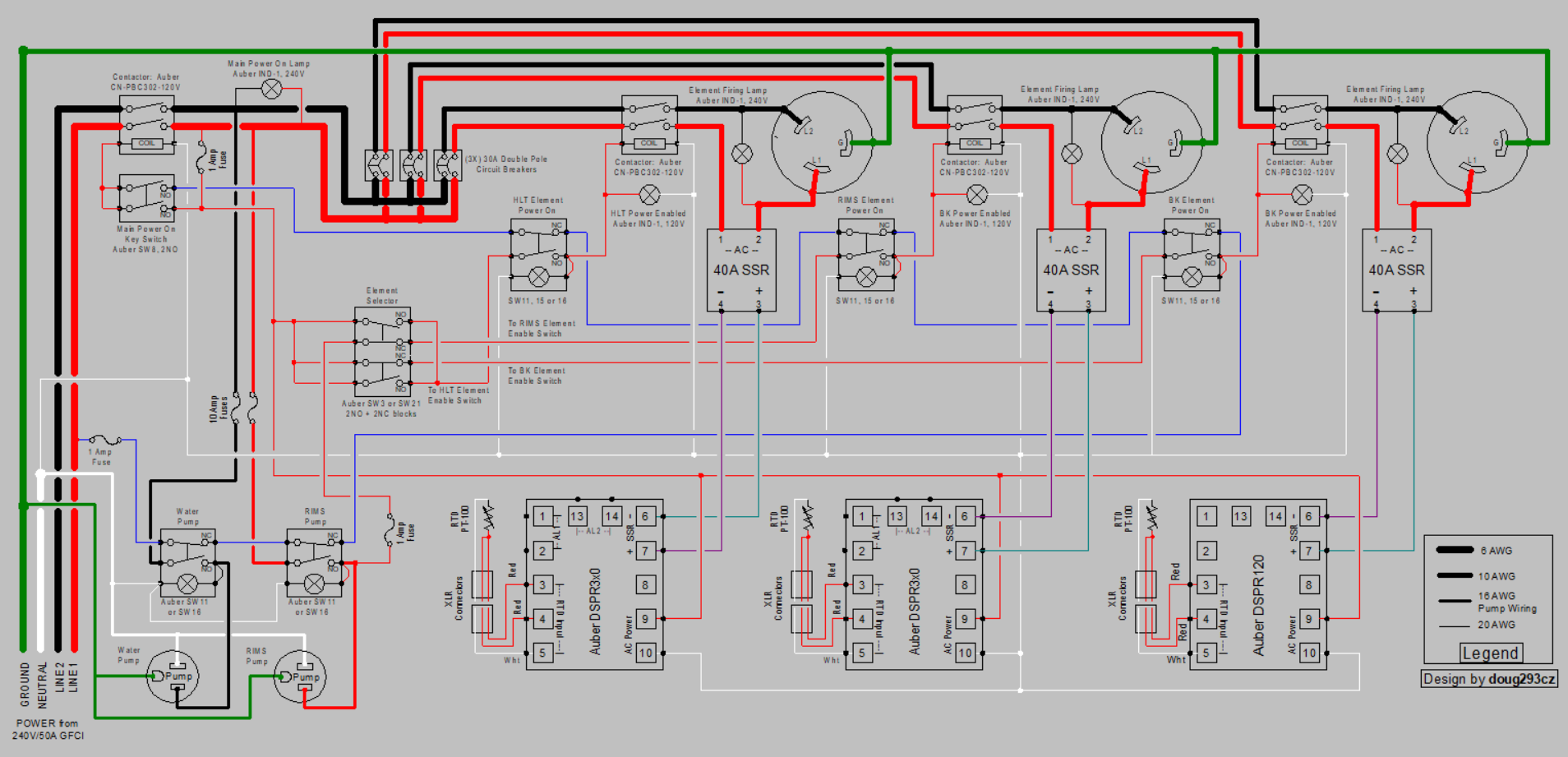
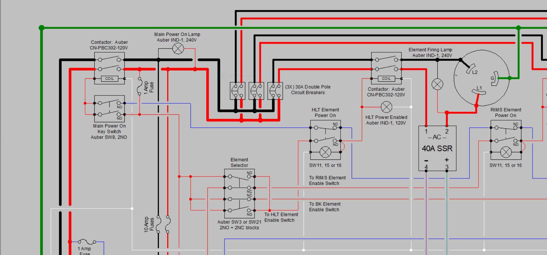
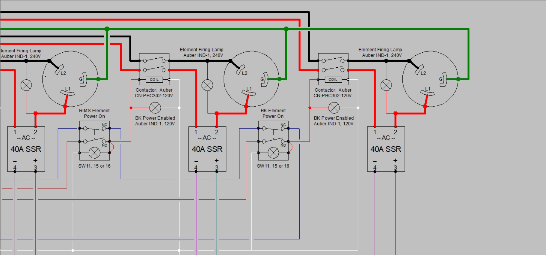
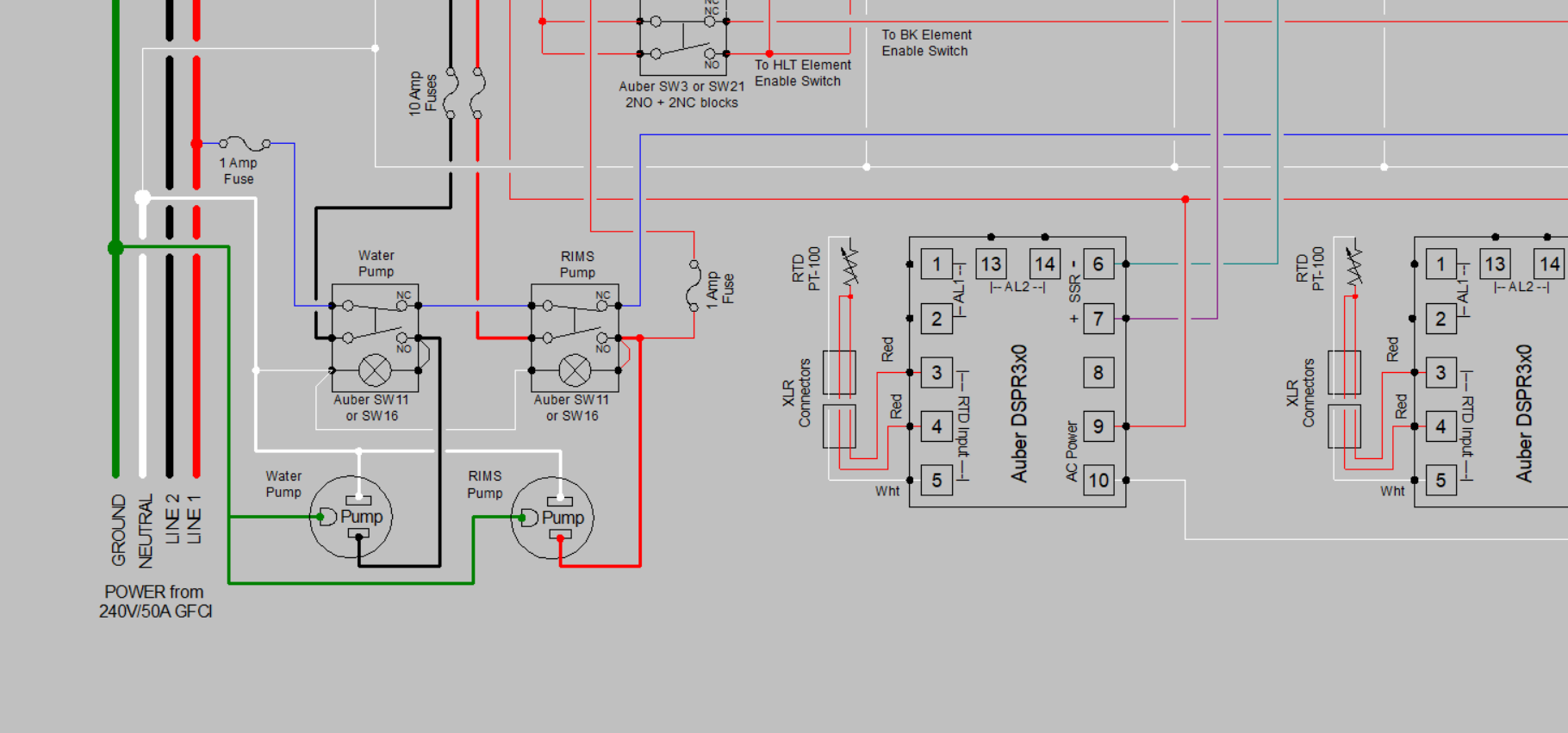
Yes, I have completed one design. The drawing is huge, so I have five pics, the entire design, and each of the corners where you can see the detail.

Any 2 of 3 elements.PNG
Any 2 of 3 elements UL.PNG
Any 2 of 3 elements UR.PNG
Any 2 of 3 elements LL.PNG
Any 2 of 3 elements LR.PNG


Brew on :mug:
 
You could do the ""any two of three" using solid state logic. Requires a different skill set for construction. Also there reasonably priced boards that give you a bunch of relays on a single board to make wiring easy.

ETA I just recalled I put this together a few years ago.

https://www.homebrewtalk.com/threads/sainsmart-relay-board-user-guide.523263/
Lots of ways to do things, but if you want to go solid state logic, then you have to add a low voltage power supply to your panel.

Brew on :mug:
 
I have a question in regards to the contactors. Would you be able to use the Auber DIN Rail mounted contactor (Model DRCN - 32A, Coil Voltage 110V (2-Pole)) in place of the CN-PBC302-120V?
 
I have a question in regards to the contactors. Would you be able to use the Auber DIN Rail mounted contactor (Model DRCN - 32A, Coil Voltage 110V (2-Pole)) in place of the CN-PBC302-120V?
Yes. In general, there a lots of substitutions possible with different components, as long as they are appropriately rated.

Also, I have discovered an error in the schematic above. The upper left (main power contactor) needs to be a CN-PCB402-120V, not a CN-PCB302-120V (or equivalent.) The 302 is rated for 40A max resistive load, and the 402 is rated for 50A resistive.

Brew on :mug:
 
I believe I may have found a mistake on the drawing. I think the wires from the Auber DSPR3x0 to the 40A SSR for the HLT element are reversed. terminal 3 on the SSR should go to terminal 7 on the DSPR3x0 and terminal 4 on the SSR should go to terminal 6 on the DSPR3x0.

I have a question about the lamp on the element on/off switches. If the small red jumper on the right side was moved to the left side and the white wire on the left side was moved to the right side, would that cause the lamp to turn on indicating that switch would now be operational when the element selector switch was positioned to allow that particular element to be turned on? The light at the outlet for the element would then indicate when the element was actually powered on. I hope I'm explaining that clearly.
You are correct about the SSR control wiring for the HLT. Don't know how I got that one wrong, and the other two correct. Thanks for pointing this out. I will go back and correct.

If you move the jumpers on the element enable switches, then the lamps will indicate when there is power to the switch, regardless of the position of the switch. As they are currently wired, they indicate when the particular switch is turned on AND the switch is receiving power from the "any 2 of 3 switch" - they let you know when power is actually enabled to the particular element. The lamps in parallel with the elements indicate when the elements are actually receiving power via the SSRs.

Brew on :mug:
 
Thank you again Doug for all the work you put into this drawing.

I have made the first purchase of components needed to build the panel. I know I have a long way to go to get everything I need but a little at a time as I have the extra money to put towards it.
IMG_2712.jpg
 
Well progress is being made, slow but, progress. DIN rail blocks still need to be confirmed since I know some changes need to be made as well as I'm going to have to add a few more but, still waiting for them to be delivered. Added a few things to the original plan as well. I added a Timer PID, AMP Meter and indicator lights to let me know which elements (2 of the 3) are enabled with the position of the switch. That way it is very clear which ones can be powered on.

Let me know your thoughts.
 

Attachments

  • IMG_2961.jpg
    IMG_2961.jpg
    1.1 MB · Views: 22
  • IMG_2962.jpg
    IMG_2962.jpg
    843.5 KB · Views: 24
I know the drawing states 6 AWG but can i get away with an 8 AWG on the ground? The reason I ask is I can get an RV 50 amp cord a lot cheaper then the 6/4 SOOW cord.
 
I know the drawing states 6 AWG but can i get away with an 8 AWG on the ground? The reason I ask is I can get an RV 50 amp cord a lot cheaper then the 6/4 SOOW cord.
I would say yes, as the ground doesn't normally carry any current, and at worst should only carry current for a short fault condition. I don't know what code says about this.

Brew on :mug:
 
Strictly speaking, it may not be to code . . . . .

Can you establish a new ground/earth reference by driving a new grounding rod at a point local the brewing location?
 
Strictly speaking, it may not be to code . . . . .

Can you establish a new ground/earth reference by driving a new grounding rod at a point local the brewing location?
But then again, it might be. I seem to remember something about thinner ground lines being allowed, but I just don't know for sure. We really need a code wonk to weigh in.

Brew on :mug:
 
Strictly speaking, it may not be to code . . . . .

Can you establish a new ground/earth reference by driving a new grounding rod at a point local the brewing location?
I guess if I needed to go to that extent of installing a new grounding rod I would just spend the extra money on the 6/4 SOOW cord.

I think I will go with the 6/4 SOOW cord since going the other router is not a huge cost savings especially when you look at how much money goes into building a new control panel anyway. Also, that way I know I will be covered.
 
So, I have the control panel wired up and have put power to it and it seems to be working as it should. Going to have to figure out how to use the new EZBoil controlers compaired to my old PID controllers. Hopefully do a test run with just water in the next week or two.
 

Attachments

  • IMG_3072.jpg
    IMG_3072.jpg
    596.3 KB · Views: 21
  • IMG_3073.jpg
    IMG_3073.jpg
    805.3 KB · Views: 21
  • IMG_3074.jpg
    IMG_3074.jpg
    807.1 KB · Views: 19
I have been playing with the new controllers to attempt to learn them since they are a lot more detailed than my old PID controllers. I have been testing with just water and it seems that the mash temp is overshooting more than I think it should. If I have the mash temp set for 152, I have seen that it is getting up to 154/155.

My current setup is a 1.5 inch RIMS tube which is 16 inches long. The temp sensor is 2.36 inches long with a 12 inch 3500 watt heating element (so really only about 10.75 inches inside the RIMS tube).

Not sure if the distance between the element and the temp sensor, 3500 watt element or a setting in the DSPR320 would be causing the larger temp swings. Or if this would be considered normal.


IMG_3197.jpg
 
Back
Top