Looking for feedback on my fittings diagram

Homebrew Talk - Beer, Wine, Mead, & Cider Brewing Discussion Forum

Help Support Homebrew Talk - Beer, Wine, Mead, & Cider Brewing Discussion Forum:

This site may earn a commission from merchant affiliate links, including eBay, Amazon, and others.

worldzfree

Well-Known Member
Joined
Nov 22, 2010
Messages
98
Reaction score
1
Location
seattle
I am looking for all types of feedback on my fittings diagram as this will be first time building up something like this. I am open to any ideas.

fittingssanitydiagram.png
 
I should clarify that this is a design intended for a Brutus 10 system with three direct-fire gas burners.
 
why dont you just run a 3/4 cam locks with barbed hose fitting and not have to reduce your pump down. 3/4 is 1/2 ID 1/2 is 3/8 ID
 
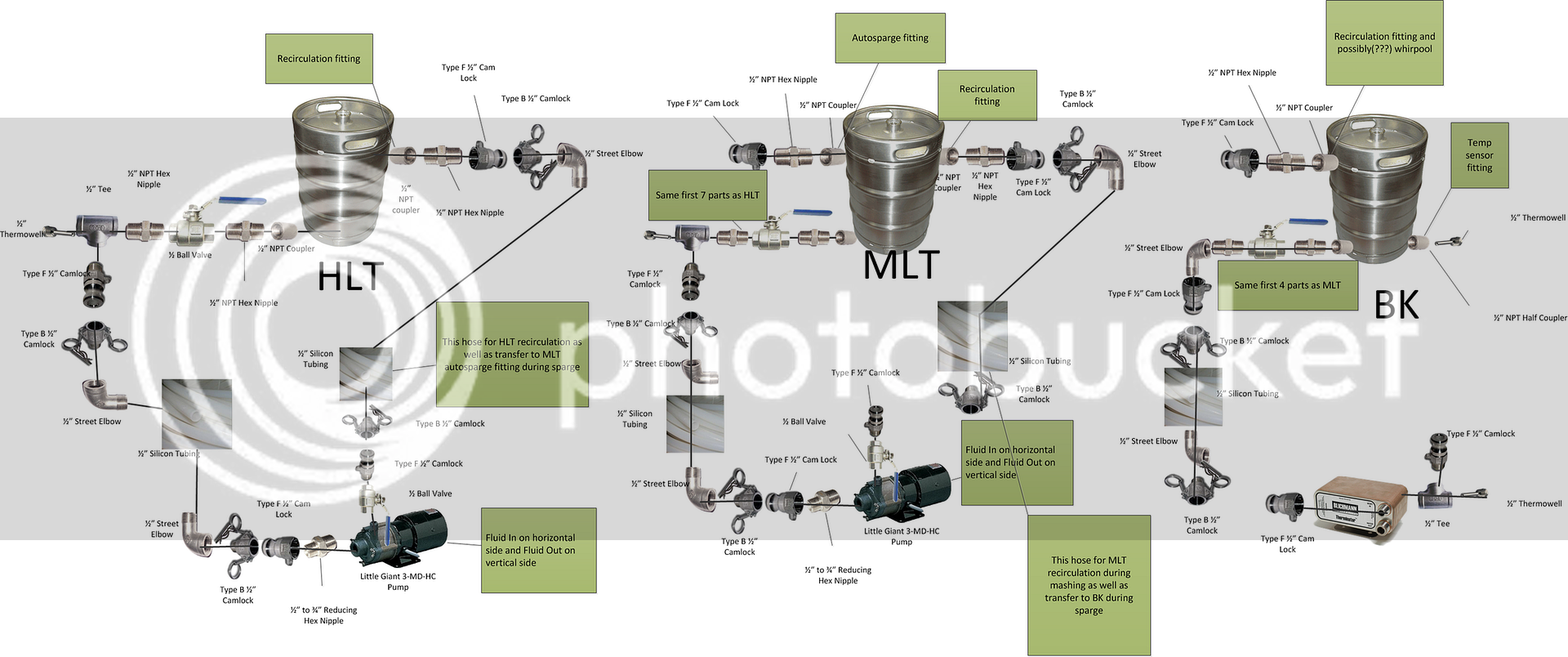
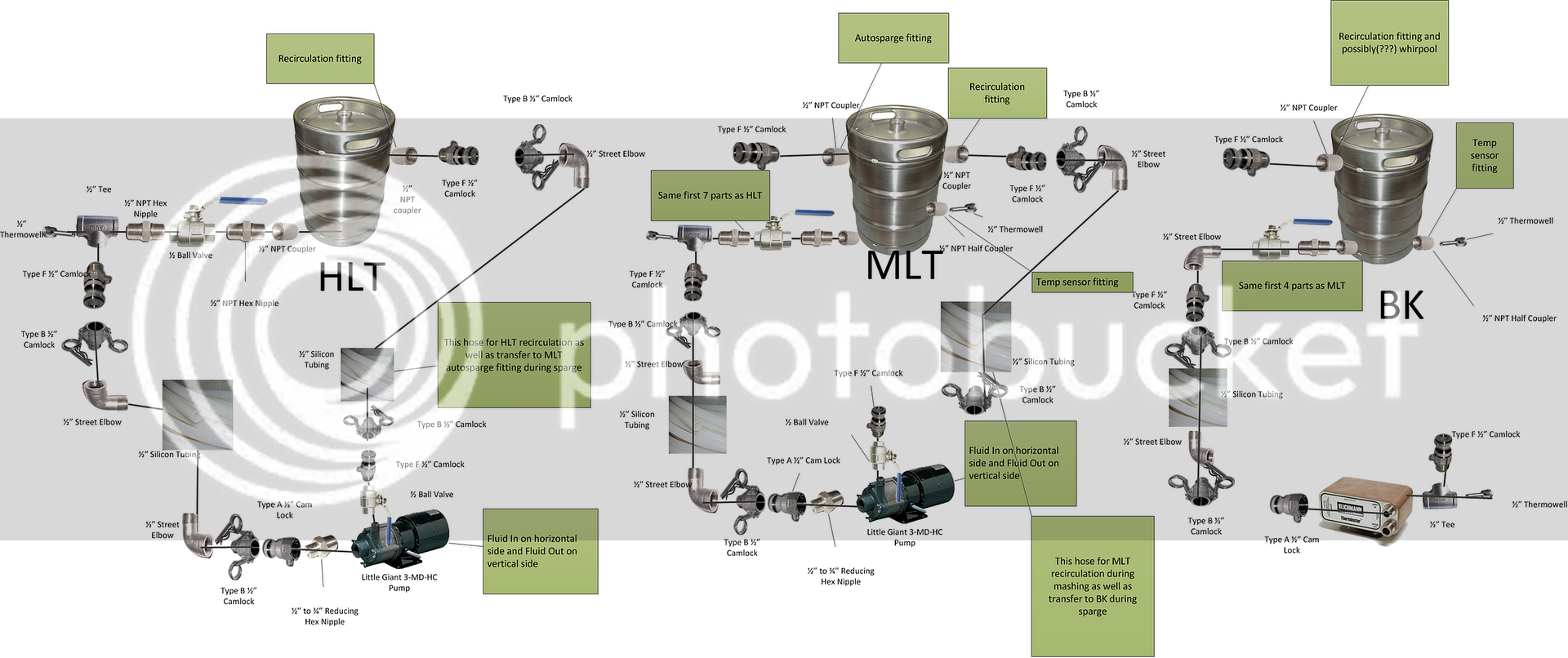
All of your male camlocks are labeled type F, even though it looks like many of them are actually type A. You could eliminate a lot of the hex nipples if you switched a bunch of the type A camlocks to F, which is maybe why they're mislabeled? Same goes for the one at the BK drain valve, just flip the street 90 and use a type F instead of A. Or are you adding the nipples to get the fittings further away from the vessels, which might be needed with the 90's on the hose side of the camlocks? I've not considered putting the 90 on the hose side, and I'll be curious to know how well that works out. Depending on how high your recirculation fittings are mounted some of them may need valves added.

As for the comment about 1/2" ID fittings actually being smaller, that applies to the barbed fittings, which I don't see any of in your diagram. You should have a full 1/2" of flow through the whole system the way it's drawn.
 
Thanks for the feedback. I agree. I adjusted the drawing to:

  • Eliminate as many hex nipples
  • Flipped the BK elbow and removed a hex nipple there
  • Added a MLT thermowell port for an additional temp sensor

fittingssanitydiagram-take2.png


So I first saw the idea of using street elbow from BobbyM. He was discussing using street elbows to reduce the chance of pinching off the tubing when hanging down from the side of the fittings as well as increasing the flow because the barbs are rather restrictive.

Here's the video I watched where he talks about it.

[ame="http://youtu.be/U_vzNDM9S5Q"]http://youtu.be/U_vzNDM9S5Q[/ame]

I am not sure if I gleamed everything he was saying though.
 
I use 90's or T's in some places for the same reason, but I mounted all of mine between the male camlock and the vessel (like you show on the BK drain), rather than between the female and the hose. I don't think it really matters much either way, but it works better for how I have my system set up and makes the hoses all identical, which I like for versatility. It also required fewer fittings for me to do it this way, but I suppose or your system it would add a couple fittings. It also allows for fewer turns with my plumbing (faster flow). The way you show it has double turns at the HLT and MLT drain. I also used threaded fittings as opposed to barbed to maintain a full 1/2" just like you're doing.
 
juanmoore, not sure i follow. can you describe the parts in order that they occur to have a standardized hose system?

i see your point about the elbow at the end of the hose on the HLT and MLT (going from Type B + Elbow + silicon to Type B + silicon). i will remove.
 
All of my hoses are just the silicone with a type B camlock on either end. The elbows (or T's) to remove strain where needed are all attached to the vessels rather than to the hose. You've already got one of them plumbed that way on the BK drain. So instead of coupler -> male cam -> female cam -> elbow -> tubing, it would be coupler -> elbow/T -> male cam -> female cam -> tubing. You wouldn't need elbows where you have the thermowells, because you already have the T's there. This may or may not be what works best for your system, it's just how I did it because it works well for my system.
 
Back
Top