Keezer cycles every 2 seconds

Homebrew Talk - Beer, Wine, Mead, & Cider Brewing Discussion Forum

Help Support Homebrew Talk - Beer, Wine, Mead, & Cider Brewing Discussion Forum:

This site may earn a commission from merchant affiliate links, including eBay, Amazon, and others.

mattrennert

Well-Known Member
Joined
Jul 15, 2009
Messages
53
Reaction score
2
Location
Platteville
Just built a temp controller for the keezer using a cheap JLD7100 temp controller. When i run Auto-Tune it seems to work, but when it finishes, it wants to kick the compressor on and off every few seconds. I just cant figure out how to keep it running until it hits a low setting, then shut off until it reaches an upper limit. I took out the other temp controller i was using, so my beer is in peril....
 
PID control is not going to work for this application, it cycles power as it tries to control temperature by varying on-off time in relation to difference in measured and set point temperatures. Do like others have with the Auber PID controllers and use the alarm function and relay output to provide compressor control without constant compressor cycling by setting upper and lower limits far enough apart to prevent short cycling.
 
Will the mechanical relay wear out after a period of time? That's why I was trying to use the ssr output and pid, no moving parts.
 
You can use a SSR. You need to set up your controller for digital ( on/off switching) operation, not PID. You should also set a minimum off cycle time of a minute or so, to prevent issues with your refer unit. Short cycling of compressors will cause overloads and possible shortened life.
You can use a mechanical relay, most commercial equipment uses them. Just try to tune the control to prevent short cycling.
 
So these are my three options, is option 0 essentially on/off control?

0: Relay Alarm output; SSR Disabled, normally used for upper lower limit alarm trigger control.
1: Relay J1 PID controlled output: SSR Disabled. Contact controlled output.
2: Relay J1 as alarm output; SSR PID controlled 12 Volt output. Know as No Contact controlled output.
 
It looks like your alarm output is on/off. Is there a dead band? If so, this could work for you. A dead band (difference between on/off commands) of a degree or so would make the alarm output function just like the OEM temp control does. This would give you some time between compressor cycles.

Back to the PID; can you set cycle times for the SSR output?
If so, you may be able to set off cycle timing to a minute or so.
 
Could you take a look at this? I know, this is a lot of information, but...

For some reason the Bb on table 3 is not present on the controller...

5793725955_69322417ee_b.jpg


Note 1:
0: Relay J1 Alarm output; SSR Disabled, normally used for upper lower limit alarm trigger control.
1: Relay J1 PID controlled output: SSR Disabled. Contact controlled output.
2: Relay J1 as alarm output; SSR PID controlled 12 Volt output. Know as No Contact controlled
output.


Note 2:
This controlled has 3 type of auto-tuning control methods already built-in.
0: Universal PID control suitable for increase/decrease fast speed of change of temperature application.
1: Gradual change PID control is suitable for applications that require steady change of temperature and speed of temperature change is not critical.
2: Fussy logic control suitable for system with oscillation and sensing signal delay.

Note 4
Proportional Band (P): When P increases, fluctuation of object being controlled decreases. When P decreases, fluctuation of object being controlled increases. When P value is too small, system may become non-converge.

Note 5
Integration time (I): its purpose is to reduce static error. When I decrease, respond speed is faster but system is less stable. When I increase, respond speed is slower, but system is more stable.

Note 6
Differentiation time (d): its purpose is to control in advance and compensate delay. Setting d-value too small or too large would decrease system stability, oscillation or even non-converge.

Note 7
Integration control range (SF): It defines integration range limits. When |SV-PV|<SF, integration
control is activated.

Note 8
Full power/complete off range (bb): It defines temperature range limits that the heating/cooling
element is either fully on or fully off. When |SV-PV|>bb, heating/cooling element could be either full power heating or complete not power.

Note 9
Control Period (ot): When ot gets smaller, heating/cooling cycle is drive faster, system respond speed is faster. But when using contact control (Relays), contacts wear out faster. When contact control (Relay) is used, normally set ot=5~30. When non-contact control (SSR) is used, normally set ot=2.

Note 10
Digital Filtering (Filt): Filt=0, filter disabled; Filt=1, weak filtering effect; Filt=3, strongest filtering effect; Stronger the filtering, more stable the readout, but has more readout display delay.
 
Could you take a look at this? I know, this is a lot of information, but...

For some reason the Bb on table 3 is not present on the controller...

5793725955_69322417ee_b.jpg


It looks like you might be able to fake out the alarm mode to work for you.
See table 4;
Set the AL1 setpoint for your target temp for the refer unit, say 42-deg.
Set the parameter AH1 to the high limit above setpoint, say 45-deg.

As for the Bb parameter missing from the controller, I don't know.

In my experience I would use a PID system for valves, dampers, speed drives etc, processes that ramp up/down.
For cycling motors, I use digital, on/off control, either directly, or via a contactor/relay.
Your controller likely uses variable pulses of the output (pulse width modulation, or PWM). Good for heating elements, not compressors.

Maybe someone here has one, and can shed more light on the subject.
 
Set control to 0 and be sure you are on cooling and then edit your al1 to 38 and you ah1 to 45. Then wire up your alarm contacts to a 115v relay that turns an outlet on and off. Plug your freezer into the outlet and your done. when the temp hits 38 it will turn on your freezer, when it hits 45 it will turn it off. Table 3 will have no effect!
 
Works like a charm. So the SV setting (target temp) dosn't really matter? Just the upper and lower limits?
 
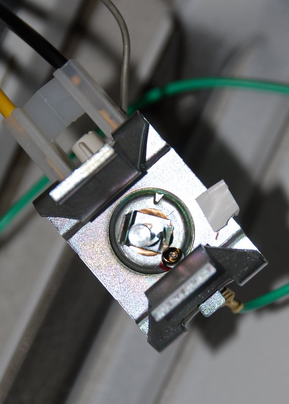
Why use an external controller? You can use a small screwdriver to adjust the set screw on the chest freezer built-in electromechanical thermostat to move it up to keezer temps. It may take a few trys to get it just right, but its free and works. Do this while the freezer is unplugged because the set screw may have line voltage on it.

The set screw may be covered by a piece of tape (was on my new GE freezer) or not. Tighten the screw (it will get harder to turn) for higher temp.
 
Never would have thought of that. Would this work on older freezers? is there any risk of permanently damaging anything? If I can do that I'll use this TC on a fermentation chamber...
 
Works like a charm. So the SV setting (target temp) dosn't really matter? Just the upper and lower limits?

SV only affects pid so it will make no difference in alarm mode. :rockin:

Let me know if the set screw thing works, that would make things much more simple for me as well!
 
The set screw is usually recessed inside the 'stat on the front side (where the dial shaft is). In the photo below the set screw is in the 5 o'clock position relative to the dial shaft and brass colored. It was hard to get a good photo. It took several turns clockwise to get it up to 40F and was covered with some thick plastic tape. I've done this on 3 different freezers, oldest was 20 years and newest is less than a month old.

thermostat.jpg
 
I'll be damned. Found it. Ill have to give it a try when ill be around the house longer to monitor the temps.

5795014893_a8e943a710_b.jpg
 
A comment about the Bb not being present on the JLD7100. On I have a TET7100 and a JLD7100 on some rancilio silvia espresso makers and use the Bb setting on the TET7100, but it was not on the JLD7100. I wish it was, because that lets it go 'full on' if it was a long way from target temp.
 
Back
Top