• Please visit and share your knowledge at our sister communities:
  • If you have not, please join our official Homebrewing Facebook Group!

    Homebrewing Facebook Group

Kal Clone and New Brewshed

Homebrew Talk

Help Support Homebrew Talk:

This site may earn a commission from merchant affiliate links, including eBay, Amazon, and others.
Last night's progress
- REWIRED amp and volt meters (see note below)
- wired pump switches, indicator lights, and receptacles

Notes - after working with all the small (22awg) wire for the Amp and Volt meters, and having it have to go past the door hinge - i thought, i have a crap ton of cat 5 cable around, i have 8 wires to run, and theres 8 in cat 5 - lets make this a LOT cleaner. so thats what i did. (didnt think to grab a pic - i'll do that later)

Tonight hopefully i'll get the brains (PIDs) wired up.

The 220v is getting put in the garage this weekend. That wont be the final place - it will soon be going to the new brewhouse in its own building, but i want 220v in the garage so i can run tests and brew if needed before the brewhouse is completed (that thing is going to be a whole 'nother project in itself)

I have to say - if you're thinking about going electric - but scared about the wiring etc - this kit is the way to go. I am right at home doing the fabrication part - but the wiring not so much. This has been great - i set it out, throw the instructions (theelectricbrewery.com) up on the iPad, follow the pictures - easy! And Kal does a great job of explaining the how and why it works as well, so when something doesn't work, you've learned enough of the concept to do some trouble shooting.

I'm loving it!

time - 3 hrs
Total - 31hrs
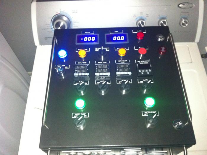
Photo 2013-06-27 07.31.51.jpg
 
Not a lot got done this weekend (at least on the control panel itself)
We did run a new 50a 220 circuit to the back of the garage (where it will also be run to the new brewhouse when time comes)
So now i can test and even brew in the garage.

Got a sweet little package in the mail saturday - Kal and Mike at theelectricbrewery.com sent me a PID collar for the Boil PID! Thanks guys!

So now its back to wiring, hope i can get the insides wired up in the next few days - then on to making temp probes and installing heating elements. Maybe with the short work week i'll be able to fire up at least the HLT and work out any bugs between HLT and MLT.

waiting on my new Boil Kettle keg that should be around soon!
 
Nice Job! I got my DIY control panel kit today and hope to start the build later this week. 4 day weekend because of the 4th of July couldn't have come at a better time. Always good to see someone else building one of the DIY kits - gives that extra boost of confidence that I can tackle this thing. Quick question - in the updated DIY information sheet I got with my kit, it references the placement of the safestart interlock on the backplate opposed to the door in Kal's build instructions. Have you decided if you are going this route and if so, where on the back plate you will be placing it? I didn't see it in your pictures (if I totally missed it in your pics I apologize). I was just curious to see what your plans are. Also, I love the idea of using the cat5 for the amp and volt meter, seems like it will definitely make routing the wires easier and cleaner. If you happen to have any pics of the wiring that would be awesome. Thanks in advance and good luck with the rest of the build.
 
Hey Kian -
You're gonna love it. Make sure you check out the building your brewery forum at theelectricbrewery.com. Tons of great info, and Kal answers all the questions that get posted.

I'll get some pics of the wiring up here in the next day or so. But here's what i used cat5 on.
Volt/amp meters (4+4)
Temp Probe
SSR signal

I broke up the temp probe and SSR like this
HLT/MLT = 6 wires (3+3) on one run.
BK and SSR signal (3+4) on another run.
Worked out great. And the colored coding makes it easy to route, no tracing wires back to source, which at this point in the process is damn near impossible.

It's driving the OCD side of my brain insane. But I'm almost done adding wires and then i'll clean everything up!

Progress last night -
All PIDs wired, Timer wired, Alarms wired, signal input to SSRs wired.
Tested all of above.
Made up one temp probe for testing - still need to calibrate, but was able to get signal and demonstrate raising and lowering temp.

Have to wire up the Element receptacles - make the other two temp probes, install elements in kettles, and wire pump lead lines.
Have some vacation stuff coming up, so i wont be running water test on full system as soon as i'd like, but i can see the light!

Time 4hrs
Total 35hrs

Photo 2013-07-02 07.26.25.jpg
 
How'd you drill the holes for the plugs on the bottom? I used my dremel for the wall-source hole and that was a complete PITA compared to using a step-bit for the LED holes.
 
How'd you drill the holes for the plugs on the bottom? I used my dremel for the wall-source hole and that was a complete PITA compared to using a step-bit for the LED holes.

Bi-Metal hole saws. DEFINITELY worth the extra cash.
made quick work of them. I bought a Milwaukee set at HD for like $25 i think? Drilled the front holes and bottom receptacle holes with the hole saws. RTD plugs were done with a step bit, front panel holes were cleaned up with a step bit.

used the same size for 220v30a and 120v pump plugs
 
anonymousbrew said:
Bi-Metal hole saws. DEFINITELY worth the extra cash.
made quick work of them. I bought a Milwaukee set at HD for like $25 i think? Drilled the front holes and bottom receptacle holes with the hole saws. RTD plugs were done with a step bit, front panel holes were cleaned up with a step bit.

used the same size for 220v30a and 120v pump plugs

Thanks for all the info regarding using the cat5 - definitely going to go this route. How did the holes on the front of the panel turn out using the step bit? Was there anything that needed to be cleaned up using the step bit? I have the 1/2 inch greenlee conduit punch for making 7/8 diameter holes which I will also be using on my kettles for the bulkheads I ordered.

Unfortunately alot of stuff I ordered for my kettles is back-ordered so I want to progress with the control panel in the mean time. Only thing I am hesitant about is wearing down the knock out punch making all the 22mm holes on the panel leaving me with a dull knockout punch when it comes time to use the punch for my kettles. Seeing that my kettles are quite a bit more expensive then the control panel enclosure id rather take a metal file to the enclosure and keep the punch for making the precision holes in the kettles. I guess I'm just curious if using a step bit opposed to a punch on the control panel caused any of the holes to come out less precise the you had hoped for?

Sorry for hijacking this thread. I will PM you going forward if you don't mind. I was having trouble finding an answer to this by searching through existing threads. Thanks again.
 
Hey Kian -
Not a hijack at all! thats what this thread is for. Ask away!

I used a 22mm hole saw on the front to make holes, then just cleaned them up a bit with a step bit.
i did NOT use a drill press. If you have access to one, go that route. You can do it by hand if you take your time, center punch your holes, and have a good powerful drill you can work slow with.

I had one hole that was off by 1/32", but was able to cheat the LED downwards and make everything line up.


Progress report -
I have everything but the interlock wired up. I'm moving on to make up an element next. I really like the idea of the interlock, and will most likely wire it in after i get all the kinks worked out.
- temp probes madeup
- PIDs configured
- Volt Meter wiring harness fixed
- elements wired in
- interior 'cleaned up' and zip-tied (ish - not all the way, but enough to make me stop twitiching everytime i open the box)
- started HLT element

I've only found 3 wiring issues so far.
- Had to switch 4&5 terminals on all PIDs - you'll know you need to do this if your PID reads a temp and wont change - (got the wiring logic from the auber site)
- I think i have my voltage meter reading off of a Hot and a Neutral - (=120) vs a hot and hot (=240)
- using a multimeter - i was reading 240 at the boil plug - even though element selector is off. I'm asking some ?s on the electricbrewery forum on this one.

time 6hrs
total time 41hrs
 
Subscribing to this. I've always drooled over these kits, so its cool to see someone do a build with estimates of time.

Mind giving a ballpark of price for the entire setup?
 
Subscribed. Also drooling over this and interested in the ballpark figures.

Happy 4th!
 
Hey Kian -
- using a multimeter - i was reading 240 at the boil plug - even though element selector is off. I'm asking some ?s on the electricbrewery forum on this one.

This is typical and expected, and happend to me. The SSR won't open (show 0 voltage) without some load on the SSR. So you're detecting a slight trickle current, or maybe the full current. If you plug your element in, or a large resistor, or maybe even a 240v rated device, you should see the voltage drop to zero. You just need to put some sort of load on the SSR so it can open. There's nothing wrong with your setup, and you're not going crazy.

-Kevin
 
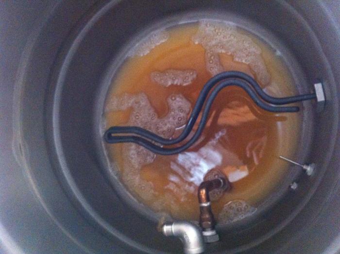
Unless I am mistaken by the picture you are referring to, that is the HLT, its only ever gonna have water in it.

The HERMS coil inside of it though, I imagine you would clean that by running hot water + PBW through it after brewday is over
 
one of the first things i noticed was that the box itself is a little different than the one Kal has, this one has two closure latches and no removable cable tray. I actually like it a little better. (very nice not having to mess with sealing that bit up)

Grabbed the tape and started laying all the front panel holes out. The two latches meant that i needed to move the buzzer, but that was ok, cause i meant i needed to move the Power indicator as well to balance it out, meaning i didnt need to cut off and move the door ground post.

Anonymous - I finally got a chance to start mocking up the measurements for the front of my control panel. I too received what I would assume is the 'latest version' of the panel with the two latches. I am following your lead with this one and moving the key and power indicator instead of relocating the grounding post. Aside from that I followed the same layout that Kal has on his site. One thing I noticed is that when measuring 1 1/2 inches in from the left of the panel for the key/power indicator, the hole seems awfully close to the foam seal on the inside of the door. Did you follow the same measurements from Kal's site as far as the vertical spacing 1 1/2" --> 4" --> 6 1/2" etc? If yes, did you have any clearance issues when installing the key/power as far as the seal on the inside getting in the way?

Also, for some reason the adj dc power supply I received is one-board with two units connected. Did you receive the same set-up and manually seperate the two power supplys from eachother - or did you receive two seperate units? Mine honestly looks like the manufacturer just forgot to cut the circuit board leaving the two units attached to one another.


I followed the spacing from KAL and to be honest, i didnt get nervous until i put the switch in place. Actually worked out fine.

My adjustable DC boards came as 2 pieces. Post up a pic, i'd like to see that!
 
I have brewpot envy.

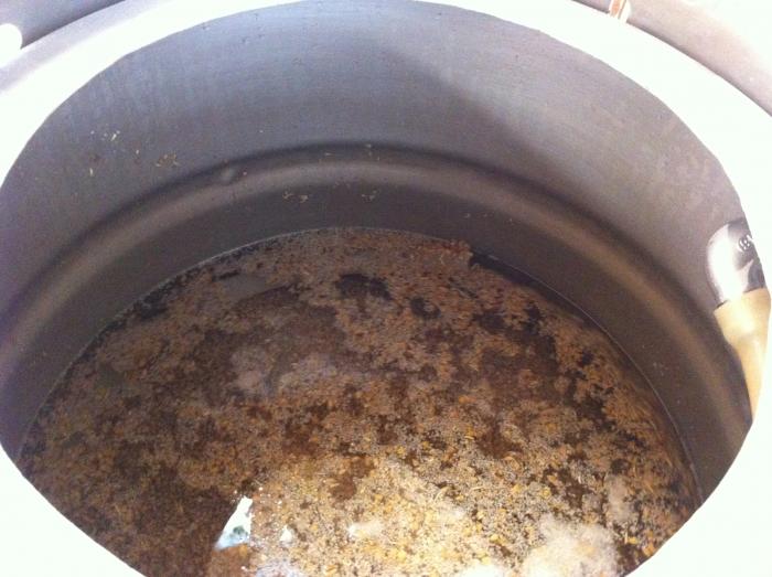
How do you clean that thing out (bottom picture post #2)?

Thats the HLT - you know, i've had that coil out probably 6 times since taking that picture, fixing leaks etc on fittings, and still never scrubbed it out (task tunnel vision).

I have scotchbrite pads i scrub everything down with, but once i clean that vessel, it should stay clean as it will only see water. the junk thats in there now is because i used to use this vessel as my Boil Kettle.
 
PROGRESS REPORT!

First off - i know - this post is pointless without pictures - and I'll apologize because i've been fitting in work on the system when i can, and haven't really stopped to take pictures. But i will post some up tonight when i do my water test.

Went on vacation last week, but worked saturday and sunday like a banshee trying to get things ready to finally brew.

here the progress:
- control panel finished (have not done the safe start interlock, I'll do this when i get bored)
- pumps wired
- boil kettle top and bulkhead holes cut and drilled
- boil kettle fittings installed
- boil kettle element installed and wired
- boil kettle boil test

So i am operational! I have to put some new hose barbs on the new fittings tonight, and should be ready to do a full water test.

Hoping to brew on saturday for the first run.!

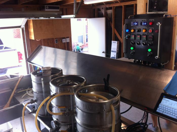
Right now everything is set up in the garage temporarily until i run the power out to the new building.
 
I'll be with in-laws on saturday, and not brewing like a good brewer should :( You should live-cast your first brew day on here with plenty of pics, so we all can brew vicariously.
 
Well..the wort making was a success!
The entire brewsession was very enjoyable, everything worked the way i wanted it to, no suprises - it was GREAT!

Have a few things to get used to/figure out, but all in all it was great!

Had some fellow brewers come over and hangout. had three 'generations' of homebrewers there - the guy that helped me get into brewing, me, and a guy i helped get into brewing.

Will need to fine tune the ramp to boil transition to avoid boilover, and refine my chilling/whirpool process.

The recipe for the day was a single malt, single hop pilsner (with ale yeast) i call Opa's Rasenmaeher.

As soon as its done fermenting, i'll be running a batch of Oktoberfest - and will have to do it ale style cause i'm so late.

Lessons learned -
- realize that if you're doing this build with keggles, you have a constraint on strike water/HLT volume you will want to take into consideration

- because of probe placement in HLT and MLT - temps only read correctly when pumps are recirculating. is not a problem, because this should be happening all the time, but when you forget to reopen a valve on your HLT and cant figure out why your temp is so low ;)


I'll post up sourcing for the parts NOT in the theelectricbrewery.com DIY kit a little later. I'm very happy so far with all the parts and service of all the guys i have worked with has been OUTSTANDING. That, i think is a nod to HBT itself, because i went with the vendors i did based on the experiences you guys have all had. enjoy!

Photo 2013-07-23 06.49.41.jpg


Photo 2013-07-23 06.49.52.jpg


Photo 2013-07-23 06.49.46.jpg


Photo 2013-07-23 06.49.31.jpg


Photo 2013-07-23 06.50.01.jpg
 
Lookin' Great! I love the control panel. I've got to get to building something to replace my apartment wooden stand... Soon!
 

Latest posts

Back
Top