Jurassic eBIAB Build

Homebrew Talk - Beer, Wine, Mead, & Cider Brewing Discussion Forum

Help Support Homebrew Talk - Beer, Wine, Mead, & Cider Brewing Discussion Forum:

This site may earn a commission from merchant affiliate links, including eBay, Amazon, and others.

Dplonk87

Supporting Member
HBT Supporter
Joined
Nov 4, 2015
Messages
29
Reaction score
11
After spending some free time looking over the forums for the last year I have decided to move to eBIAB. I currently am brewing with a 3 vessel system made up of two coolers and an 8 gallon MegaPot 1.2 boil kettle. After having a few kids and needing more space in the garage for kids toys it is now time to shrink my brewing space to one vessel.

Starting out I just want to thank everyone for posting such valuable information regarding their builds, they have been hugely helpful on the path to electric brewing.

Step 1 - Upgrade Kettle:
I intend to brew mostly 5 gallon batches but may try the occasional 9-10 gallon batch. I decided to let Spike do all of the "hard work" and went with a custom 15 gallon kettle with 4 1.5" tri-clamp ports labeled below.

full


In the process of working with Spike on the kettle the information came out regarding their Single Vessel Brew System. I liked the idea but wanted to make my own controller, however I did confirm with them that my custom kettle would work with their basket. I plan to recirculate during the mash and will start out with a brew bag and false bottom but will likely get the Spike basket when it is available.

To keep things simple I also ordered a heating element, a shorty pickup tube for the drain port, and a side pickup tube for the whirlpool port.
 
Last edited:
Sounds good. My only comment is that most do their WP port farther up, presumably to get more vertical exchange. Lower like you have it may prevent interference with a nah or basket though.
 
Sounds good. My only comment is that most do their WP port farther up, presumably to get more vertical exchange. Lower like you have it may prevent interference with a nah or basket though.

Appreciate the feedback, I went back and forth on that but went with a port down low for concerns about interference like you said. I think the pick-up tubes are supposed to be rotatable so if I have any issues maybe I will be able to angle it up.
 
Step 2 - Control Panel:
I found several wiring diagrams posted on the forum that I used as inspiration for what I would like to do. Auber Instruments has various sizes of enclosures with knockouts, I intend to use the Black 10"x8"x8" found at the link below:

https://www.auberins.com/index.php?main_page=product_info&cPath=34&products_id=892

The plan is to configure it with the components in the layout below:

View media item 70881
View media item 70882
The 5500W element will be controlled by an EZBoil DSPR320, power to the element will be switched and a 240V light will indicate when the element is firing.

There will be two 120V outlets, power to each will be switched. One will be intended for a pump with the other being an auxiliary outlet for phone charging, speaker, etc.

Auber Instruments also offers an Ammeter and Voltmeter as a pair which I intend to use.

Here is the Bill of Materials I laid out for the enclosure and components:
View media item 70886
 
Last edited:
Step 3 - Wiring Diagram:
This is definitely the part I'm hoping for some feedback on, I used inspiration from the wiring diagrams in the following threads:

https://www.homebrewtalk.com/forum/threads/totally-building-an-electric-biab-system.635682/

https://www.homebrewtalk.com/forum/threads/yet-another-ebiab-control-panel.660119/

https://www.homebrewtalk.com/forum/threads/advice-on-control-panel.597209/#post-7820518

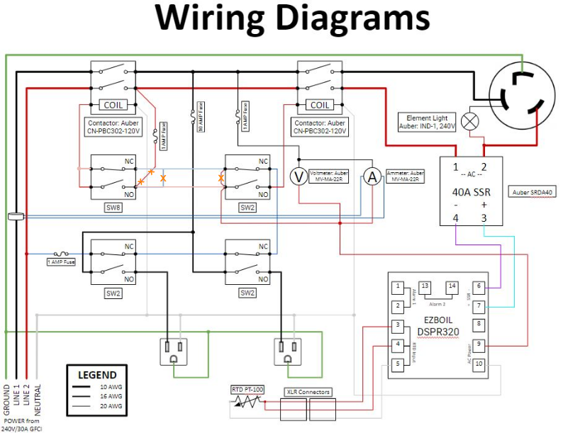
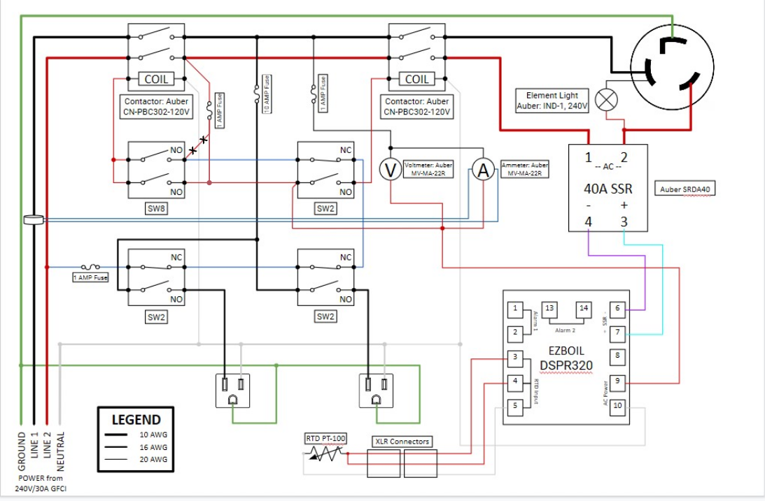
I like the idea of the safe start interlock on the element, pump and auxiliary switch and have incorporated that into the diagram in what I believe to be the correct way.

View media item 70883
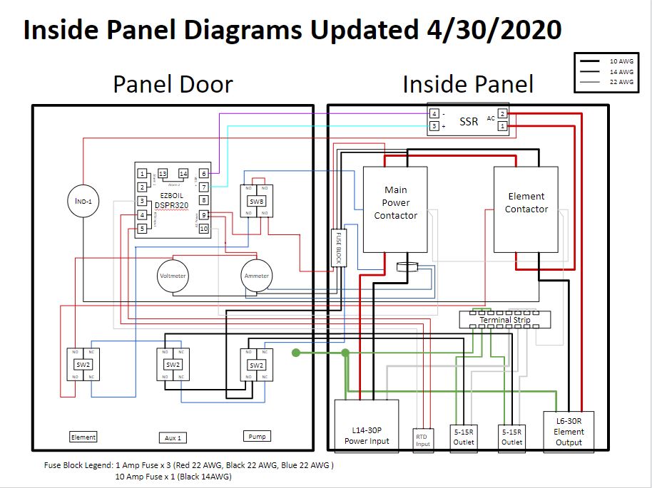
I also tried to layout what I think the wiring within the actual panel would look like to give myself a road map to follow.

View media item 70884
Again I'm definitely hoping for some feedback on the diagrams as this is my first attempt at it. My only real question is about the use of 20AWG wire vs 22AWG wire. I know that Auber Instruments has a wiring kit that includes 22AWG wire which I intend to purchase for the build. From my understanding of other posts as long as it is fused properly there would be no issue, but please correct me if that is the wrong idea.
 
I suggest you modify the Safe Start circuit as shown below. This version doesn't provide power to the DSPR until the main power contactor is energized.

Modified Safe Start.png


22AWG wire should be fine within the control panel when protected by a 1A fuse.

Brew on :mug:
 
Doug thanks for the quick response and advice. Looking at the updated diagram for the Safe Start Circuit, is the output of the NC block on the element switch connected to the input NC block of the keyed switch? If I am thinking about that correctly it seems the main contactor would be energized as soon as I plug it in. Or would I just use two NO blocks on the keyed switch to prevent that and connect the output of Line 2 on the main contactor to the top NO block on the keyed switch so everything still functions when the other switches are used?

View media item 70889
 
Yes, the keyed switch should have 2X NO blocks. I failed to notice that you used a 1-NO 1-NC keyed switch. Your updated schematic will work, but I would move where the Line-2 wire from the load side of the main power contactor connects to the keyed switch. (I messed this up on my updated drawing by "X"ing out a wire I shouldn't have. This would leave more of the total wiring unpowered before the main contactor is activated. See the update below:

Modified Safe Start.png


Brew on :mug:
 
Wiring diagram and inside panel diagram updated to reflect the changes that @doug293cz suggested to the safe start. I also updated the wiring size on the legend to reflect that 22 AWG wire is going to be used.

View media item 70891
View media item 70890
Anybody have any recommendations on fuses/fuse holders? Brands to use/avoid? I would like to use inline holders just to avoid drilling any holes but if that is bad practice please let me know.
 
That is a really nice kettle. I want to build one similiar. How did it work? About how much you have into the system?
 
I think the other was the thermocouple and whirlpool port.

That is correct

That is a really nice kettle. I want to build one similiar. How did it work? About how much you have into the system?

The kettle with the accessories I got was about $600, $425 for the custom kettle.

As far as the controller I got everything from Auber Instruments for about $375, still in the process of putting it all together so I will have to let you know how it all works.
 
That is correct


The kettle with the accessories I got was about $600, $425 for the custom kettle.

As far as the controller I got everything from Auber Instruments for about $375, still in the process of putting it all together so I will have to let you know how it all works.

I may do something very similar. The only thing I might do different is remove whirlpool Port and Add a recirculation port at top of pot for recirculation of mash. Then use a clamp on stile whirlpool tube I can put in after the grain basket is removed and be able to adjust height where I want it. I see utahbiodiesel makes custom brew baskets I wonder how far above heating element you want it to sit? I want to leave a little room for element but not too much because on bigger beers don't want water on top of grain to close to top edge
 
Sounds like a good plan, I thought about putting a port at the top but didn't want to limit my batch size. I then started thinking about going through the lid but when I saw Spike is working on a basket that includes a port I designed my kettle to work with that when it is available.
 
I think you'll like the system. I bought the same kettle and use a 400 micron Brew Bag bag. I'm actually using a 40-62 quart bag which is a size down from what they recommend and like the fit better diameter wise. It could stand to be a few inches shorter so eventually I order a custom one. Under the bag I use a Brew Hardware false bottom. For a control panel, I'm using an Electric Brewing Supply panel but switched out the controller for an EZ Boil.
 
Sounds like a good plan, I thought about putting a port at the top but didn't want to limit my batch size. I then started thinking about going through the lid but when I saw Spike is working on a basket that includes a port I designed my kettle to work with that when it is available.

Do you know what their basket will cost?
 
I have a question regarding the neutral side of the 120V circuit required for the pumps and the coils of the contactors. Since everything on the circuit is going to be fused for 10amps on the hot side of the circuit do I need to use 10AWG wire to the Power In Receptacle or can I use 14AWG wire?

I realized the 120V receptacles I got have 0.187" quick connect terminals, I don't believe there are any connectors the will work with 10AWG wire for the connection. I was thinking about adding a terminal strip to more easily make the connections from the Power In receptacle to the 120V but it looks like most terminal strips are designed to one size wire to be used.
Yes you can use 14AWG for the neutral. You can also drop the gauge of the hot downstream of the 10A fuse.

Brew on 🍻
 
Looks good.

Brew on :mug:
Hi,
I have been spending all my free time trying to create a wiring diagram based on the ones published by Bryan from Short Circuited Brewers, but that were actually designed by doug293cz, so thanks for that Doug! I am very happy now that I found this thread cause it's very similar to what I want to build.
I have two (probably very stupid) questions on the final diagram:
1 - There are no fuses or circuit breakers to protect the element. Is that ok? Is the protection provided by the 240v/30a GFCI breaker in the breaker box sufficient? Or we the element is so cheap that we don't care?
2 - The pumps that I check have an amparage of 1.5amp, so will having a fuse of 10amp protect it?

Thank you!
Cheers!
The purpose of a fuse/circuit breaker is to protect the wires from carrying excess current, overheating, and thus starting a fire. Fuses are selected based on the current carrying capacity of the wire. For example, if you are using 10AWG wire you need to protect it with a 30A fuse/breaker. Fuses do not protect the loads that are connected to the wires.

A GFCI is designed to protect people from electrocution. They trip at ~5 milliamps, which is much less than a lethal amount of current. A GFCI breaker functions a both a GFCI and a circuit breaker.

Using a 10 amp fuse for the pump wiring allows you to wire that part of the circuit with 14AWG wire, which is much easier to work with than 10AWG.

Brew on :mug:
Now that clarifies everything! Thank you so much Doug!!!!
Cheers!!!
 
A few updates as the build carries on:
- Added a terminal strip to help connect the Ground and Neutral wires
- Added a fuse block instead of doing inline fuse holders to better organize everything

Wiring Diagram - Updated 4-30.jpg


Some pictures of the current wiring process:
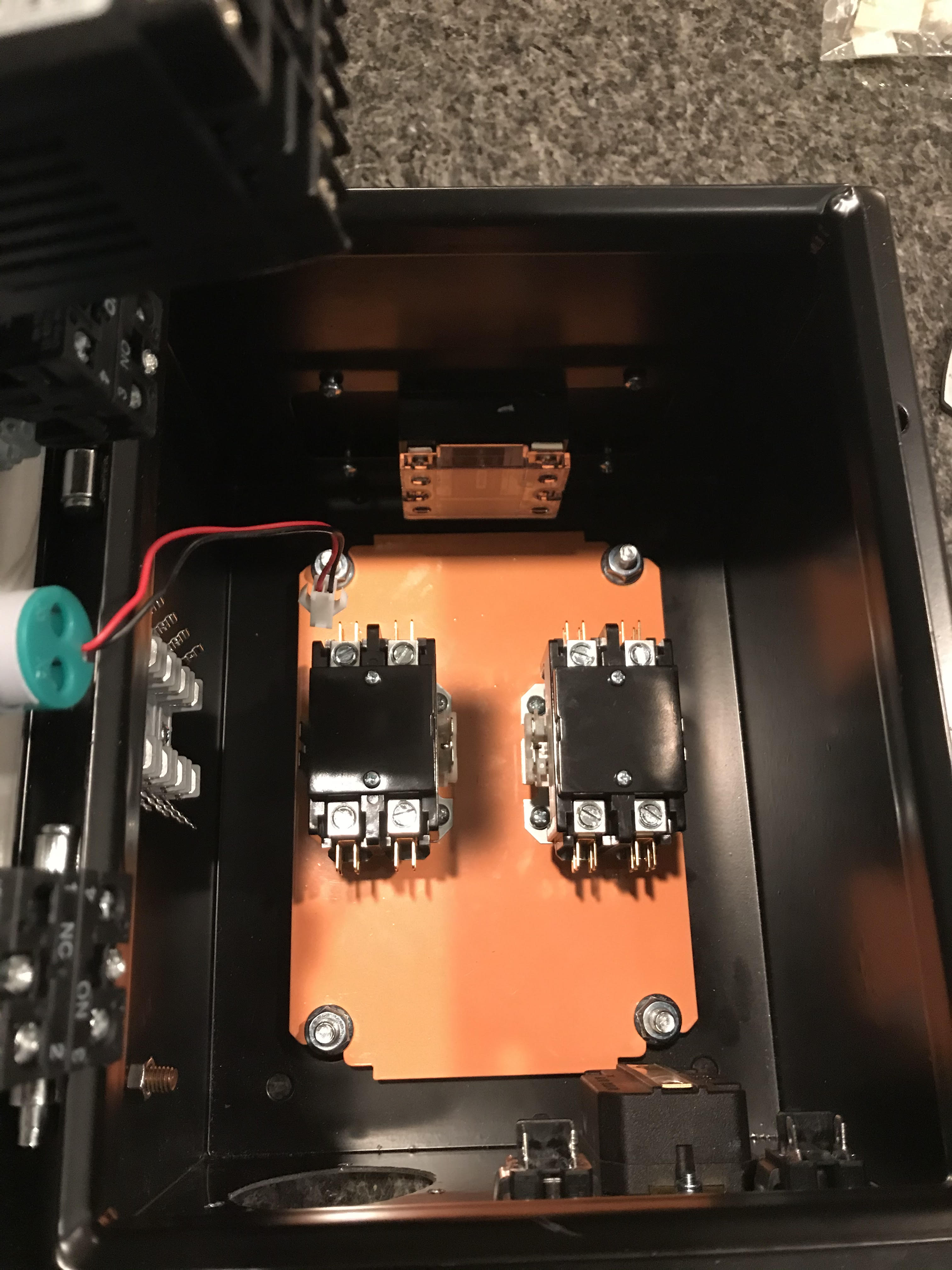
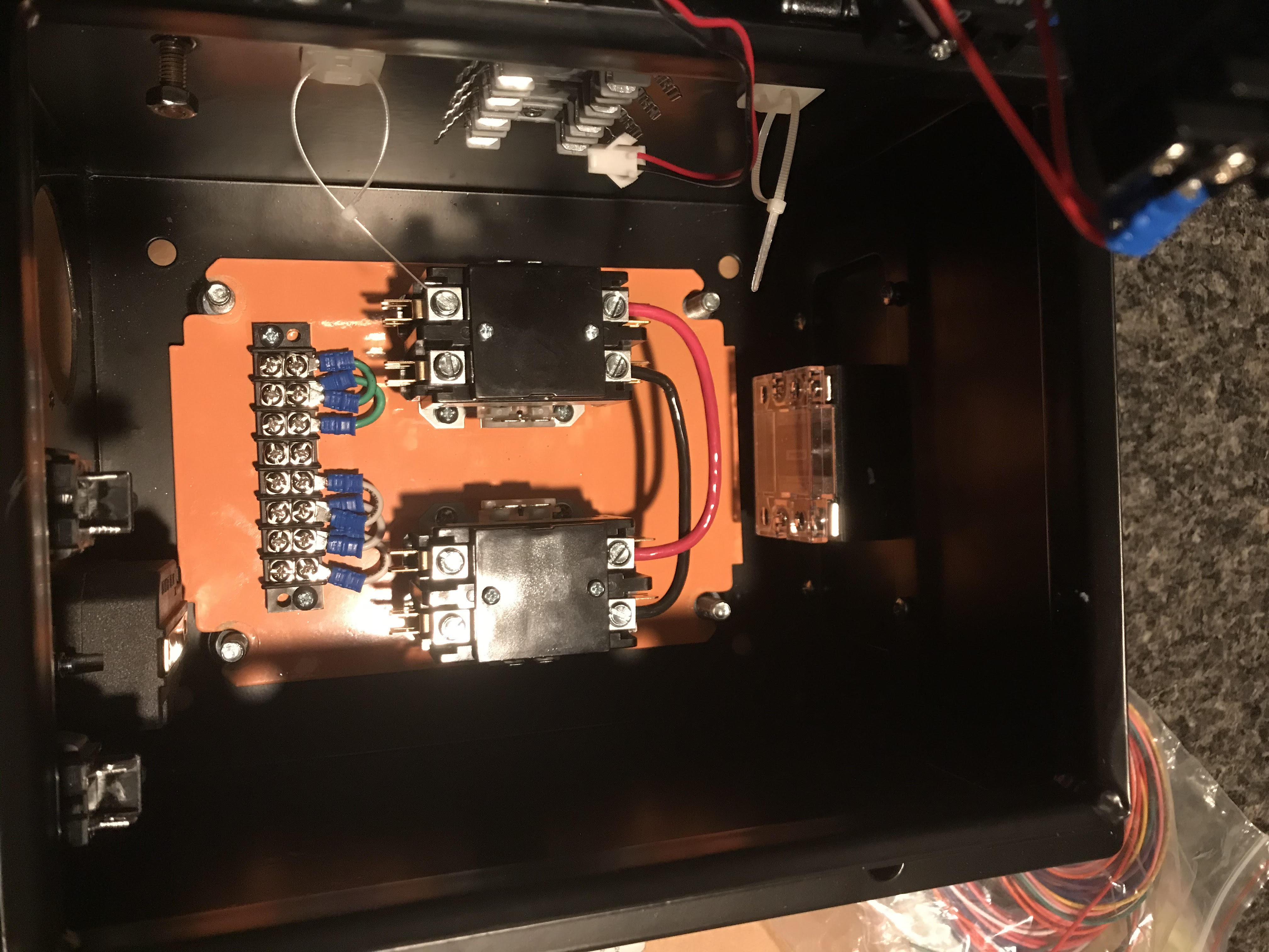
Components Installed
Components Installed with Fuse Block.jpg


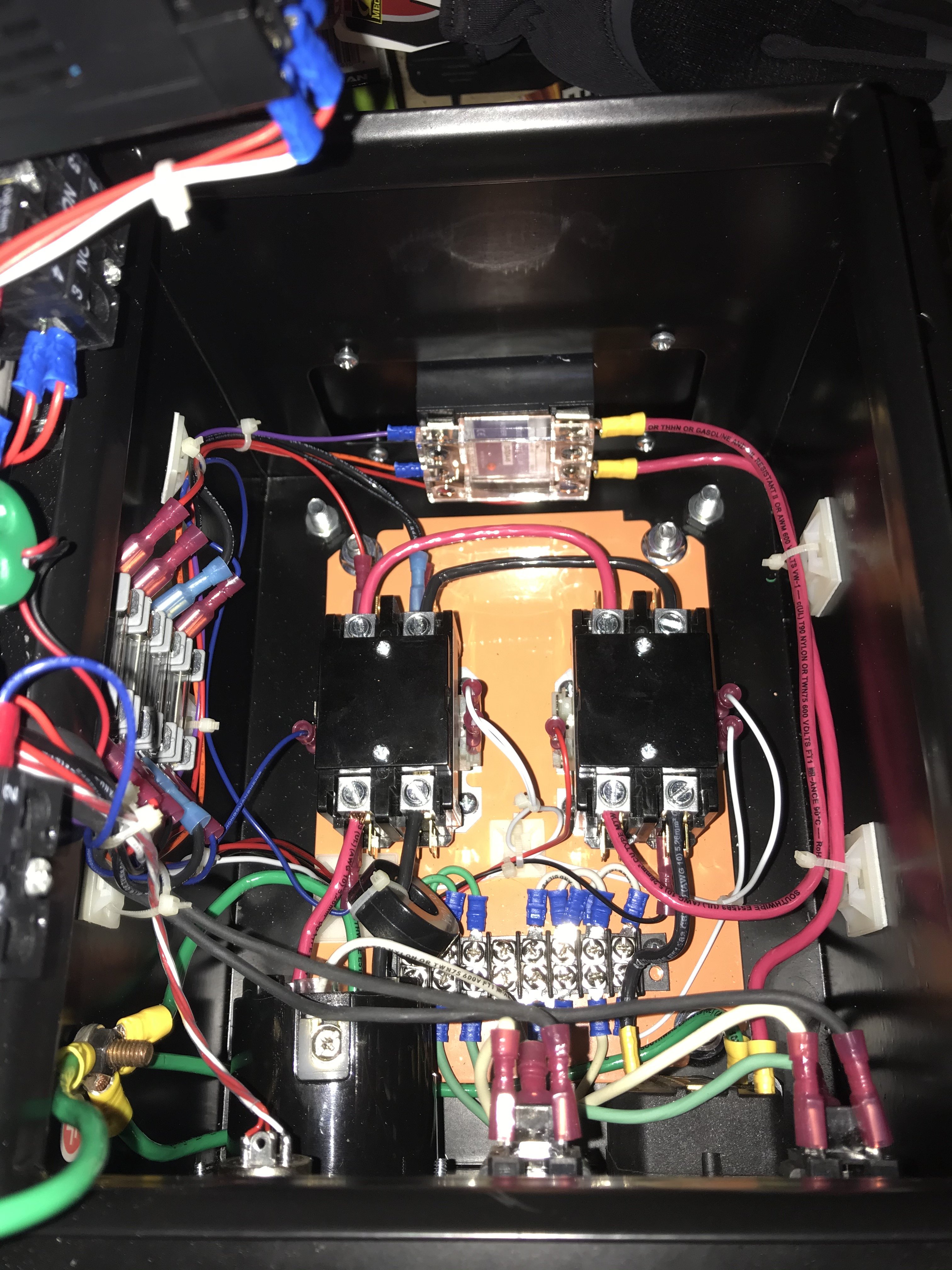
Back Plate Wiring In Process
Back Plate Wiring In Process.jpg


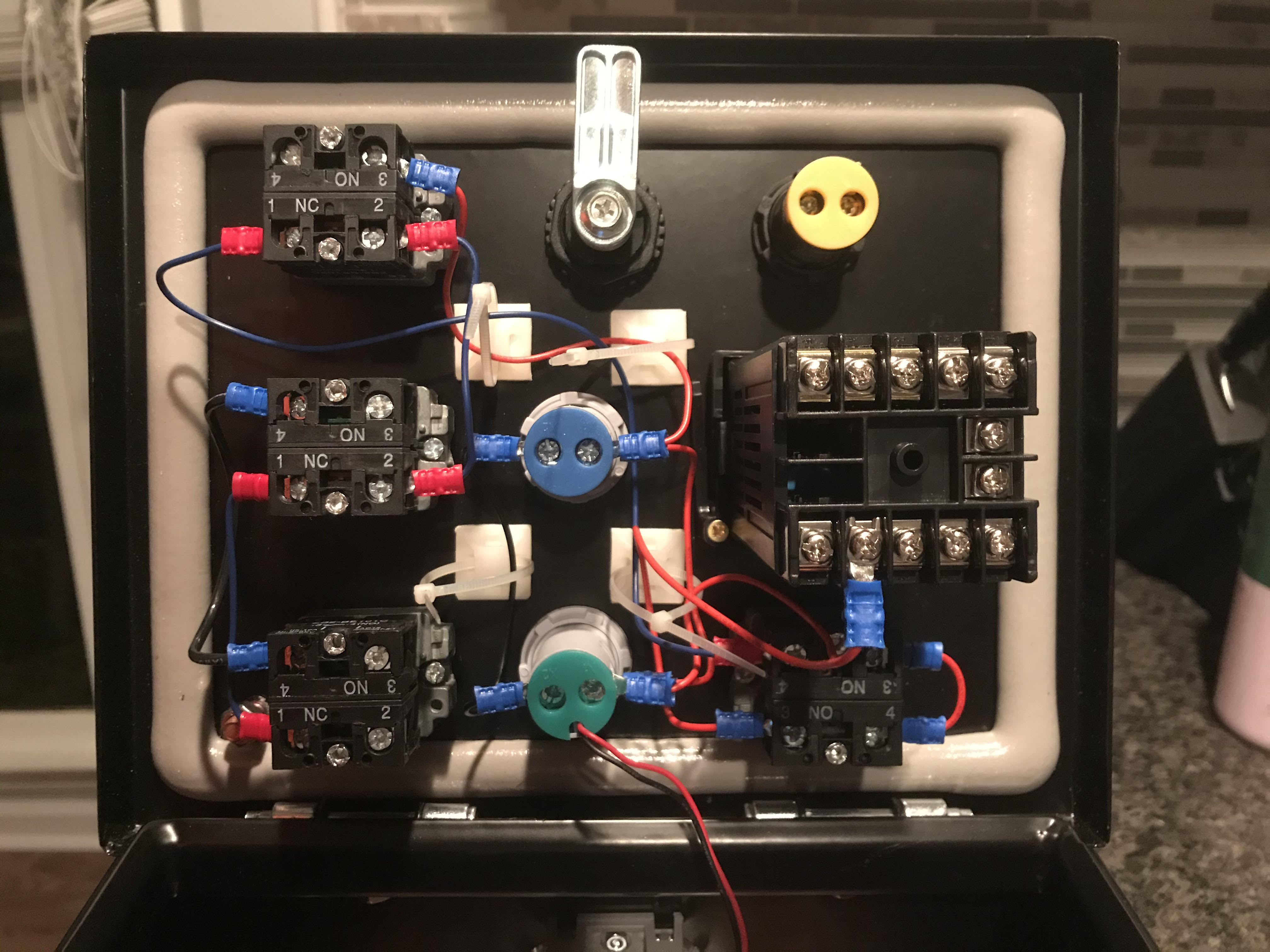
Door Wiring In Process
Door Wiring in Process.jpg
 
Finally got back to wiring after a temporary stop to build a playset for the kids. I took some pictures along the way as I progressed through wiring.

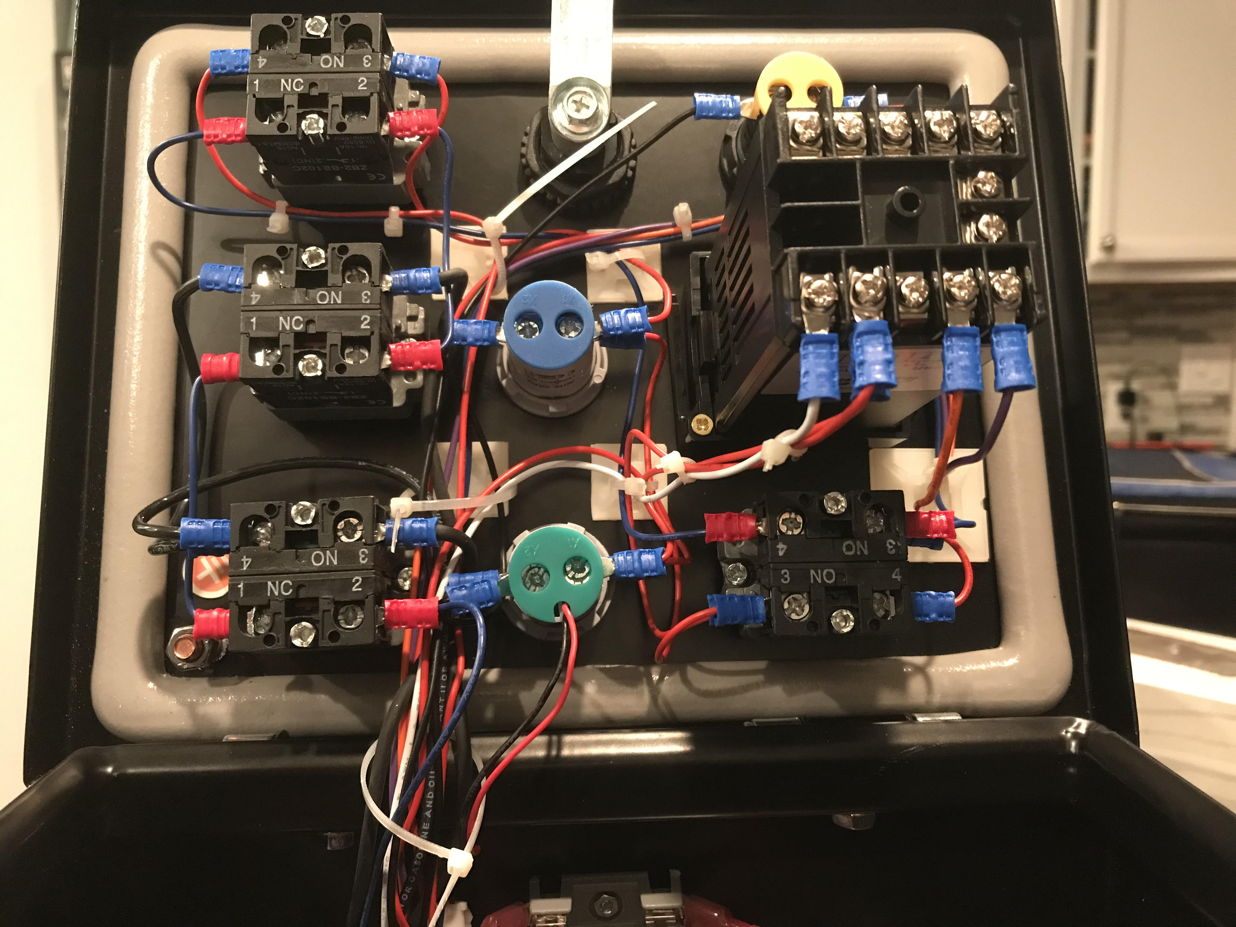
Progress on Door Wiring
Door Wiring in Process (2).jpg


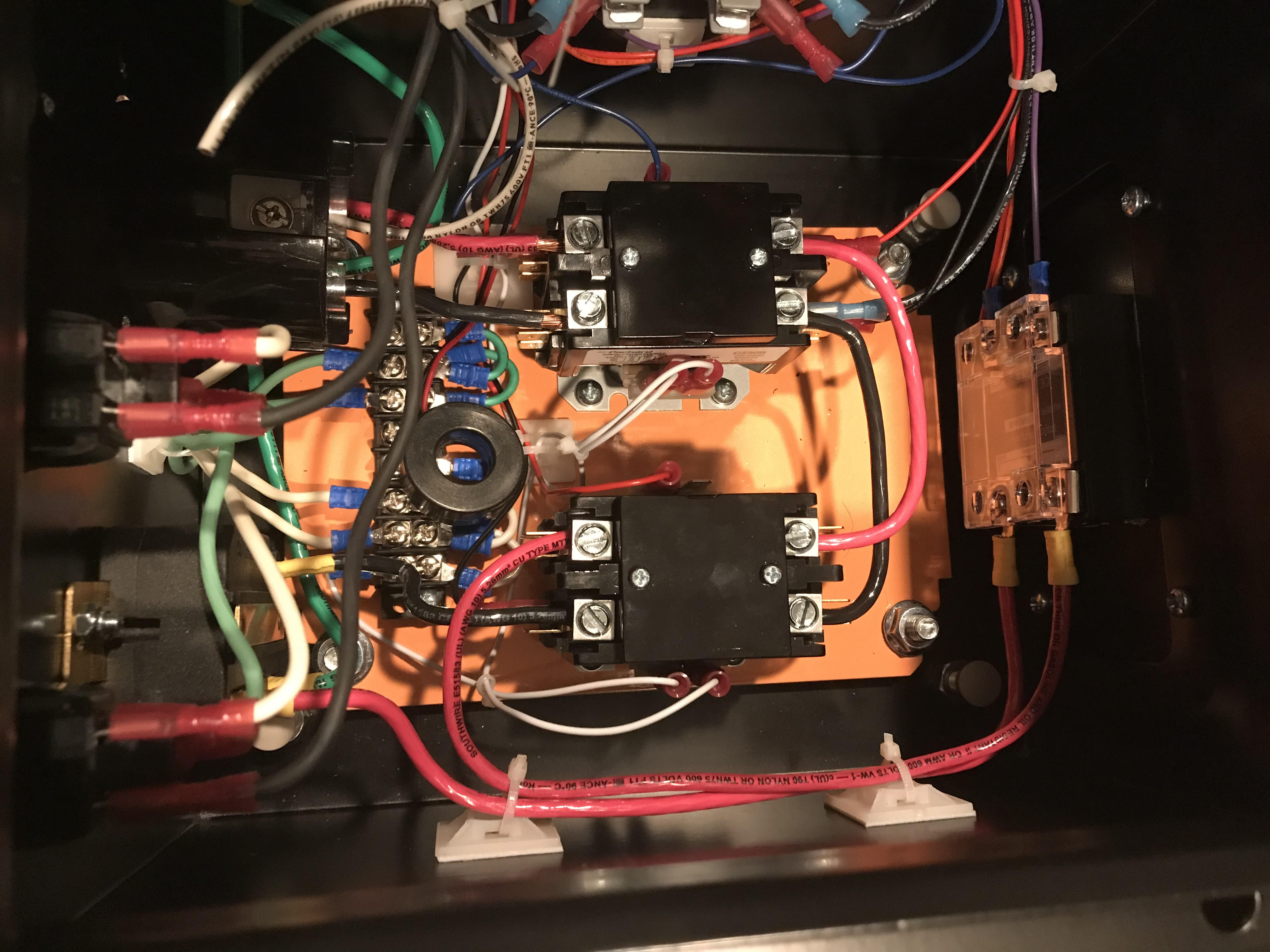
Progress on Back Plate
Back Plate Wiring in Process (2).jpg


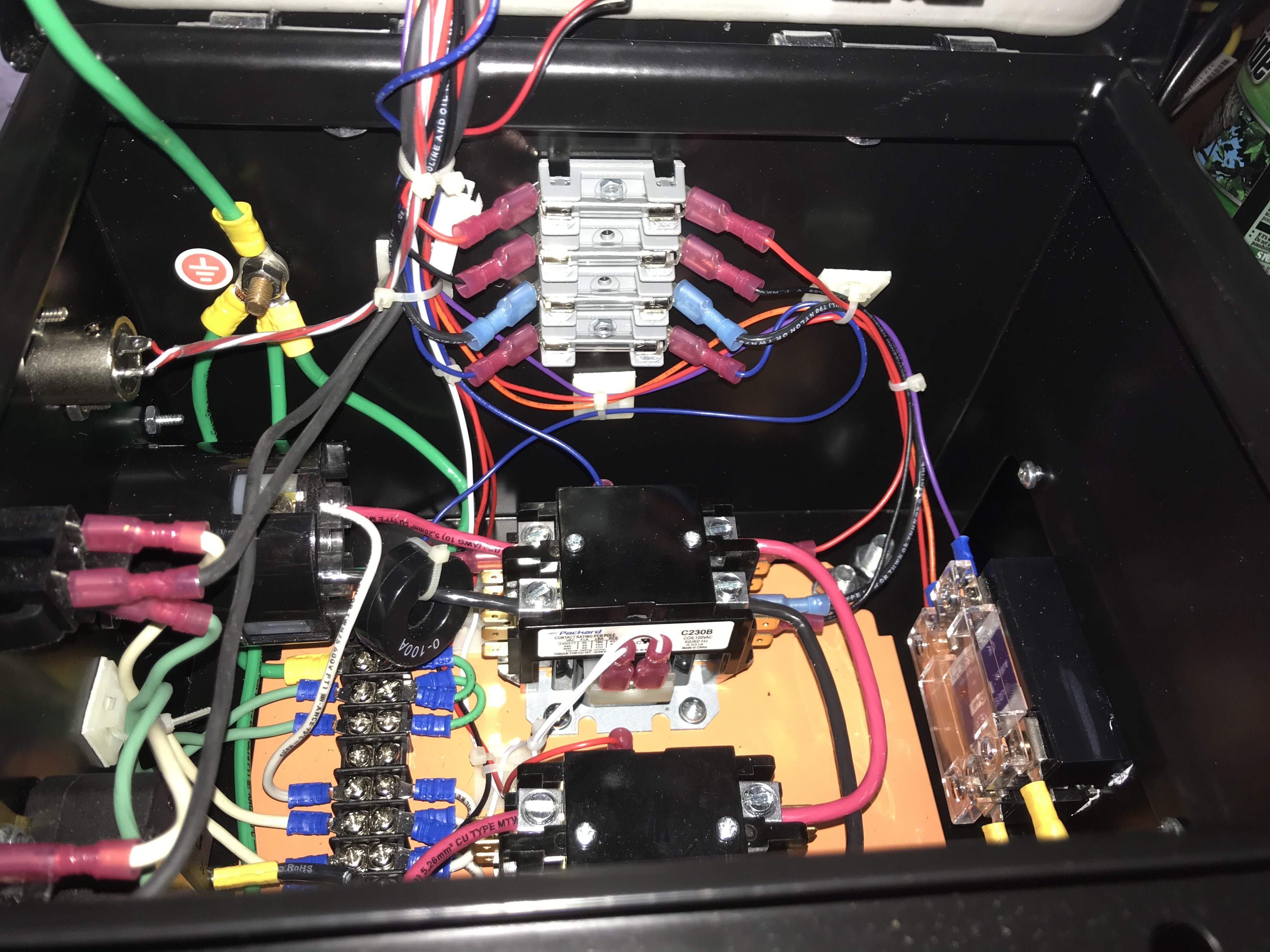
Fuse Box Wiring
Back Plate Wiring in Process (3).jpg


Finally got everything finished and secured with cable ties.

Finished Door Wiring
Door Fully Wired.jpg


Finished Back Plate
Back Plate Wired 2.jpg


Finished Fuse Box
Fuse Box Wired.jpg
 
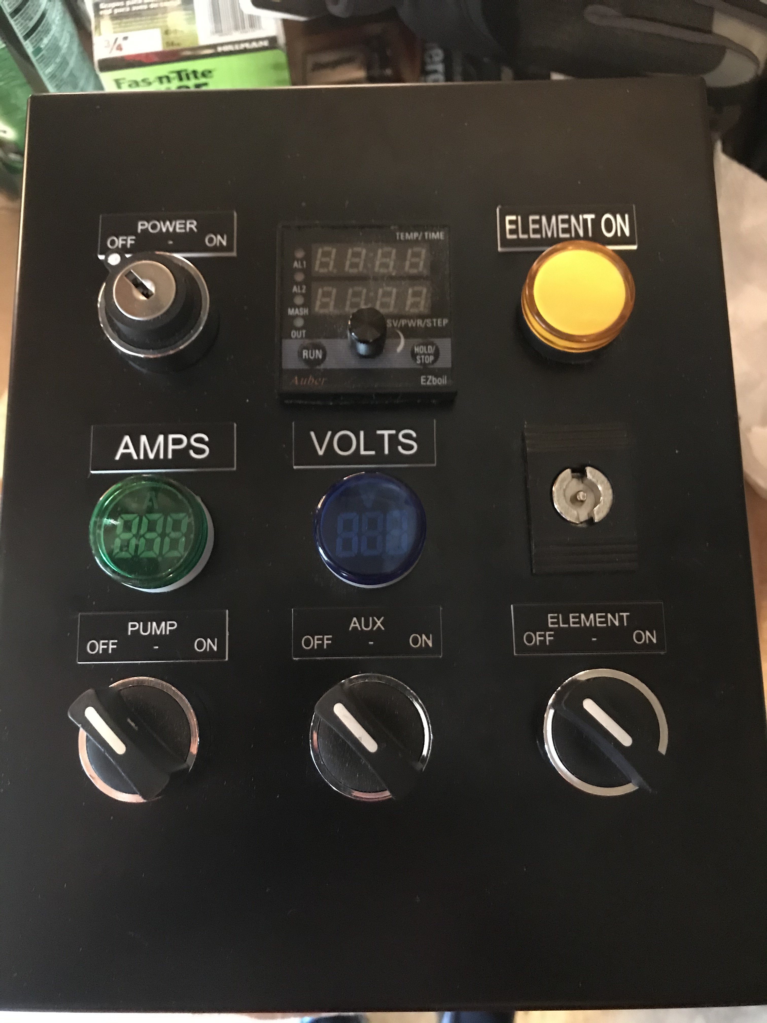
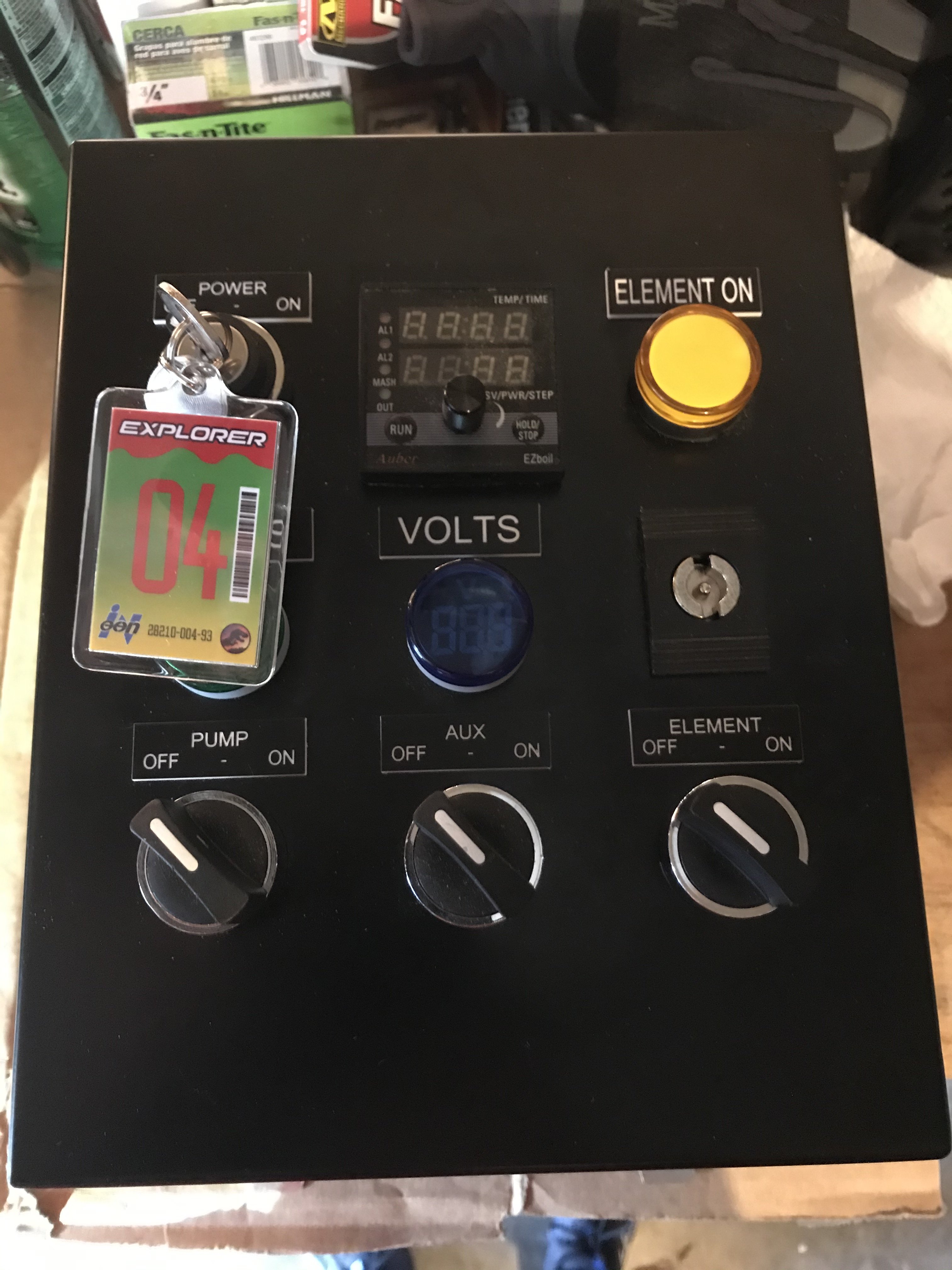
Finally here is the outside of the panel

Finished Front
Finished Panel Front.jpg


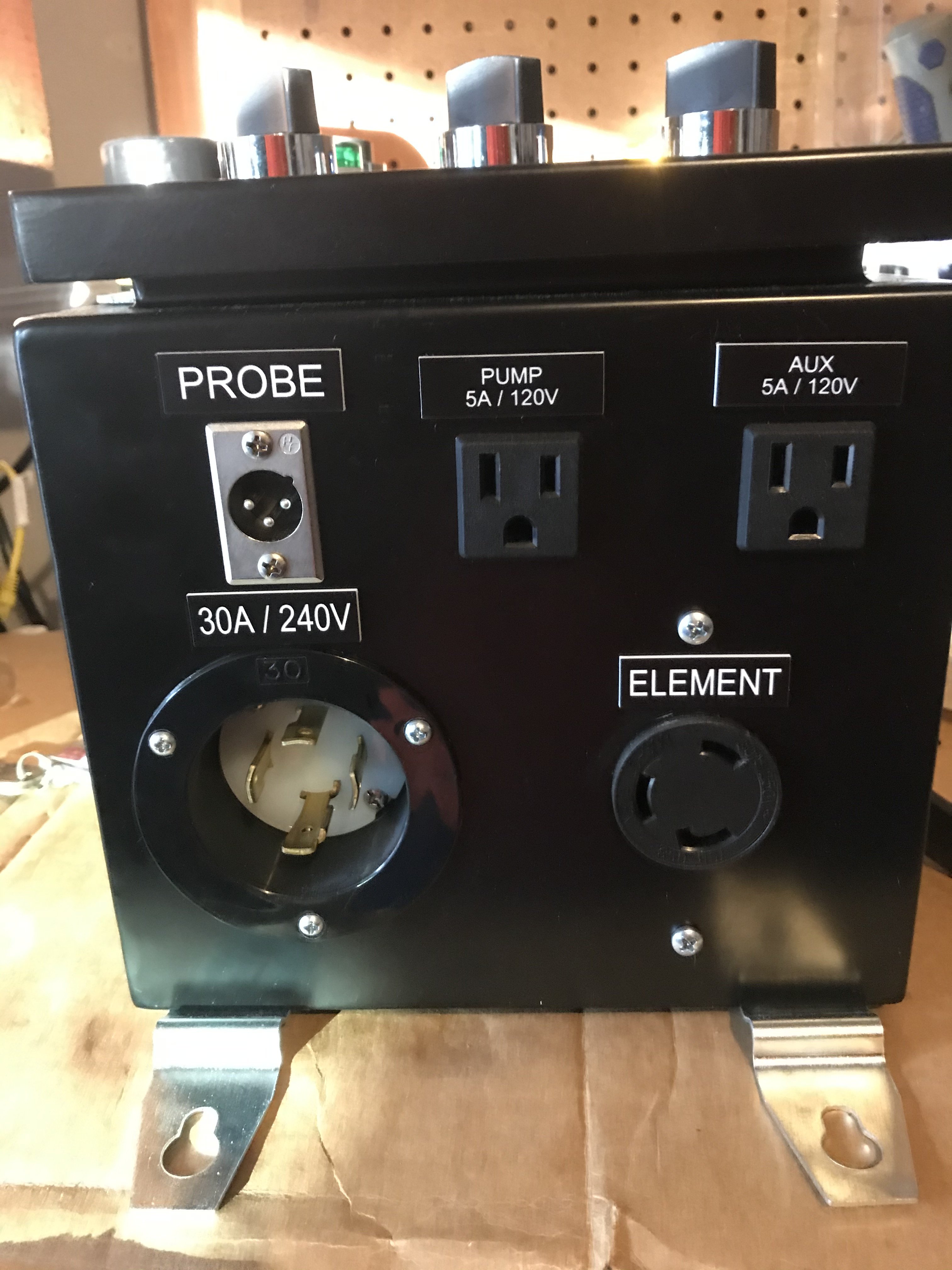
Finished Bottom
Finished Panel Bottom.jpg


With custom Jurassic Park Keychain
Finished Panel Front with Key Chain.jpg


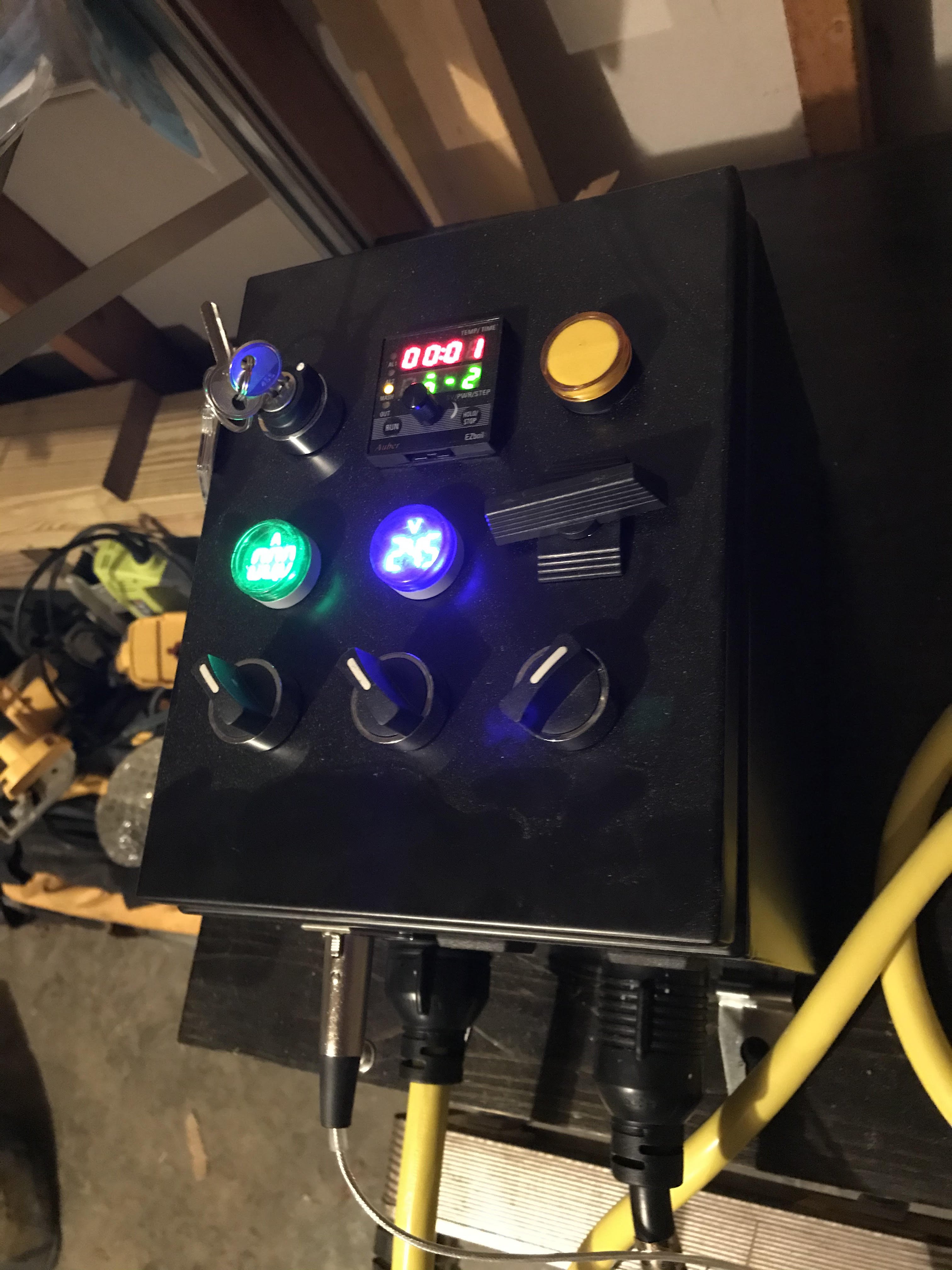
Initial Power Up
Control Panel On (2).jpg
 
Regarding recirculation, Bobby from Brew Hardware recommends, if I understand it correctly, splitting the output of the pump. Half goes under the bag to keep hot/cold spots forming around the heating element. Half goes up top to keep the mash itself constant and even temp.

I think you get the advantage ifvthe under recirculation will act as a hedge to ensure your element does not go dry in case you get a stuck mash.
 

Latest posts

Back
Top