HOWTO - Make a BrewPi Fermentation Controller For Cheap

Homebrew Talk - Beer, Wine, Mead, & Cider Brewing Discussion Forum

Help Support Homebrew Talk - Beer, Wine, Mead, & Cider Brewing Discussion Forum:

This site may earn a commission from merchant affiliate links, including eBay, Amazon, and others.
Status
Not open for further replies.
@LBussy hey I finally bought a 3d printer as was looking for your design of the temp probe holder on thingaverse. And it looks like you might have removed it. Did it not work as expected?
 
I keep telling @Thorrak that he needs to include at least a screenshot on his web page.

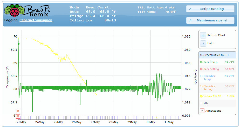
Actual differences from the POV of the user? The way it looks. After some slight differences in setup, the interface is all you are going to see. Maybe Thorrak will post a pic of his. This is a screenshot of one of my mules:

1590960144605.png


I'm not going to say that we work together on this, but we speak every day and there's not much one will do that the other will not. One of the primary differences originally was that Thorrak implemented an esp8266 controller, however, both will use each other's controllers so that difference is moot.
 
@LBussy hey I finally bought a 3d printer as was looking for your design of the temp probe holder on thingaverse. And it looks like you might have removed it. Did it not work as expected?
Not sure what happened to that, but I've uploaded it again. I did not put any thought into the upload, but it's the same piece.
 
Hi Lee,
I've finally got BLR up and running on wifi, via a wemos d1 mini ESP8266 board. All seems to work, but when there is a power outage, the arduino loses installed devices. Does this have something to do with serial settings in BrewPiUtil.py? I followed a combination of Mattrox, day_trippr and your BrewPi on wifi guides, but none of them exactly match my setup. Cheers
 
Generally an Arduino acts like that when there’s something hung up in the EEPROM. Try to erase EEPROM and reset everything and see what happens.
 
Since none of us have the same configuration, you're left with stepping through the chain to figure it out. I'd start with direct-connecting the Arduino and see if you can replicate. Continue adding components until you find where it is.
 
Does Fermentrack run on an ESP8266?
I hate to say "you're not asking the right question," but, you're not asking the right question. :)

This thread is BrewPi specific. Fermentrack is a different UI written to serve the application. It is a separate thread. Both Fermentrack and BrewPi Remix connect to a controller. Both support the original Arduino Uno, as well as the ESP8266. So, BrewPi (the firmware) runs on the ESP8266 as well as the Arduino Uno. You'd connect either of those to either BrewPi Remix or Fermentrack.

Hopefully, that makes sense.

Thank you, I totally understand what you are saying LBussy. I was playing catch up and was referencing a quote from yourself to bdogg171 where you said
"Be aware that Fermentrack and BrewPi Remix should both be thought of as the "front end" to either ESP-8266 or Arduino Uno controllers. They are almost interchangeable, it's a lot about how you want it to look/act on the front end."
And that is what piqued my interest.

I am trying to minimise the footprint on some of my installations and if I can use an ESP8266 in place of a Pi then I'm all ears.
Hope I wasn't too far out of line with the question and, on reflection, I think I jumped the gun with the question anyway as what I meant to ask (and yes, it is also not thread related) is in relation to CraftBeerPi. An no, I do not expect an answer to that here.

FTR I have now successfully used my ESP8266 (Wemos D1) with Fermentrack so have answered my own question anyway. :yes:
 
I've experienced two SSR failures over the last few months and thought I would reach out to the community for suggestions.
(FYI- This setup has been running for years so the recent failures are baffling me.)

The failure I'm experiencing is that the SSR is will "get stuck? / fail-closed?" keeping the "cooling" circuit running constantly. I know that this isn't a failure of the software configuration because the "heating" circuit will kick on to combat the dropping temperature.

I've twice caught the fermentation chamber nearly freezing my beer solid as a result of this issue.

The only fix (so far) has been replacing the SSR (which immediately corrects the issue).

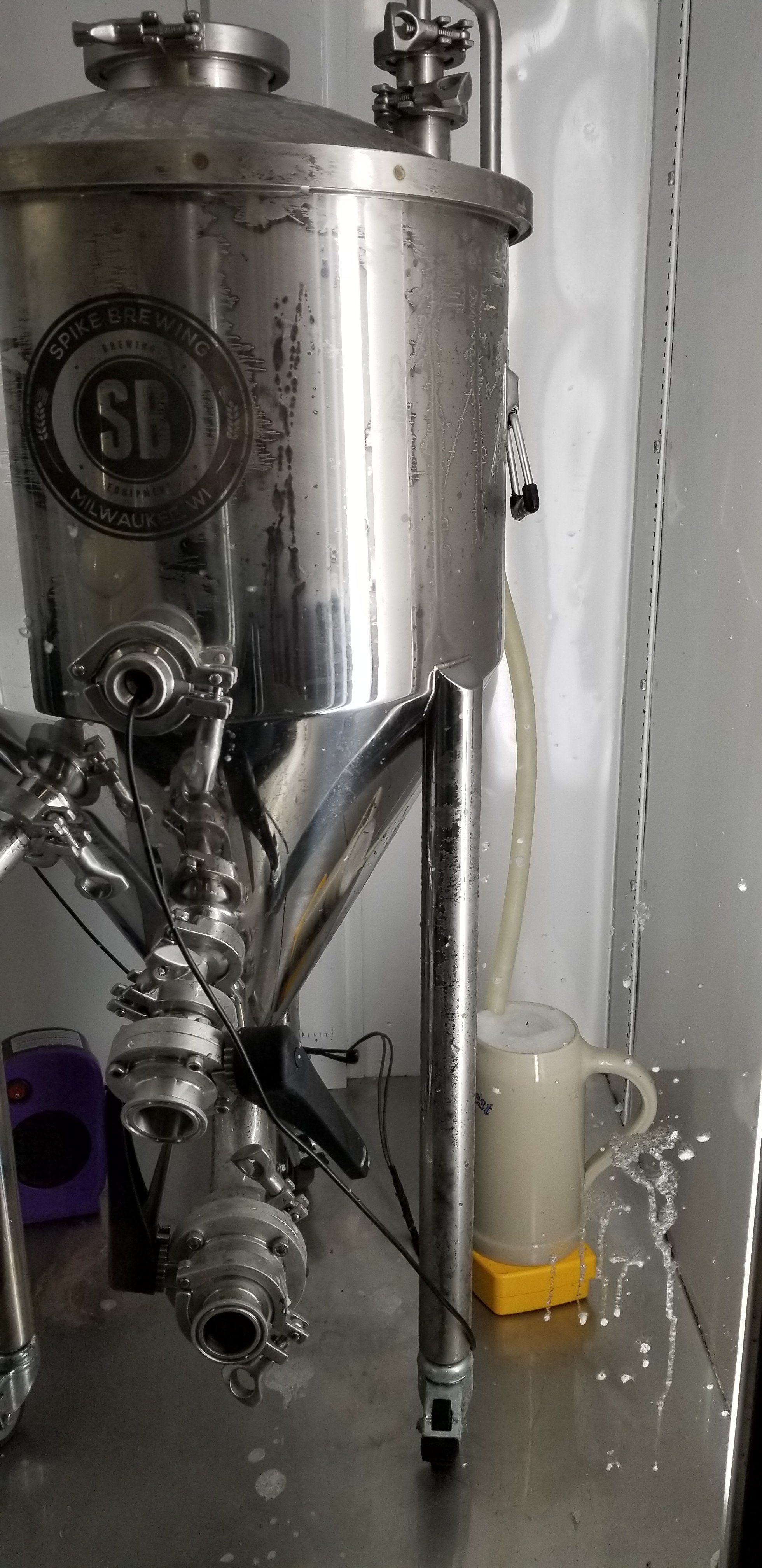
The diagram below is what I have wired/configured.

Any idea on where I can begin troubleshooting this problem?

BrewPi_Wiring.JPG
 
If everything works fine except you eventually weld the points on the Cold side relay module, I would suspect the relay module rating isn't up to par with the load it is trying to switch. You could add a slaved relay with much higher current rating - I did this for my keezer - and never have to worry about it again...

Cheers!
@day_trippr I think you and @gromitdj are probably correct.

I'm no electrical engineer, but I assume when you say "slave" the higher amperage relay you mean wiring it "in-line" with SSR that is already in place for the cold side circuit?

I have an extra ink bird SSR from my E-HERMS control panel build that I can probably use:

INKBIRD.png
 
So, just for clarification, the drawing clearly shows a dual relay module controlled by the Arduino, and my response was based on that.
If otoh you've actually been using SSRs and they're failing closed, that's a whole different problem that slaving another element may not address.

That Inkbird SSR could be directly wired to the Arduino, fwiw, instead of whatever you're using now that's getting fried...

Cheers!
 
But if you are using a dual relay board like pictured..., by slave I think day_trippr is saying that you could use the current relay to drive an AC-AC SSR that would more likely be able to handle the power required.
 
@day_trippr The drawing is correct, I'm using a dual relay module (also the component that is failing). After posting the Ink Bird SSR solution and then reading @gromitdj 's post I see that if a "slave configuration" were used, I would need an AC-AC SSR (with higher amperage). Or if I just want to omit the dual relay module from the cold side circuit I can use the DC-AC Ink Bird SSR directly wired to the Arduino.

I think I'll do that later and monitor for issues.

Thanks, everyone!
 
Last edited:
@H0phead used the term SSR, but posted a picture using relays. The failure he describes is exactly how most SSRs fail—they tend to fail ‘on’.

I feel any SSR from China needs to be viewed with skepticism. So many are marked falsely. Buy a good one from a reputable seller—I have bought several from Auber and have had a lot of success with them. Spend the money here—it could save your beer.

In the meantime be thankful the almost frozen beer wasn’t in glass carboys!
 
@hinkensj Yeah, that's my ignorance of electronic components shining through :D I thought that the "SainSmart 2-Channel Relay Module" (pictured in my diagram) was an SSR?

---

Agreed on the glass carboy...that would have been ugly.

It's probably hard to see, but my "blow-off bucket" is frozen solid (the beer was just a little sloshy)

20200401_070754.jpg
 
hah! No, "SainSmart" isn't the "SS" in "SSR" :)
SSR = Solid State Relay

So I think we're all on the same page now. There are relays used, and evidently the points are being welded on the Cold relay.
That indicates the current draw (at least on start-up) on the load is far in excess of what the relay can handle.
Now, with a new/fully functional dual relay module, you could route 5V (drawn off the Arduino) through the Cold relay NO points and send that to your Inkbird SSR control input, and use that hunky chunk of Si to switch your compressor. Or - and this depends on the control input loading provided by that SSR - you could skip the relay entirely and control the SSR directly from the Arduino...

Cheers!
 
Bing! +1 to @day_trippr if using an SSR, run it straight from the Arduino.
There are relays that can take more load than these std 10A versions so commonly and cheaply (meant both ways) available. But many may require a 12 of 24V coil supply even though many can still be switch with the 5V from the Arduino. That takes more power supplies, etc. to string together and probably not worth it.

You could try something like this: https://amzn.to/30eAH3R, but I don’t really trust the current ratings stated on Chinese things sold on Amazon...
 
The control for that hunky relay does not appear to have an opto-coupler in the path - and from the reviews it needs at least 4.5 volts to pick the relay.
The relays we typically use on this and related projects are opto-coupled with low-active inputs, so be aware "adjustments" may be required (eg: don't invert the Cool and Heat controls in the BrewPi gui, at the very least).

fwiw, I would probably put a fet or transistor between the Uno and the control input to that relay just on GPs...

Cheers!
 
hah! No, "SainSmart" isn't the "SS" in "SSR" :)
SSR = Solid State Relay

So I think we're all on the same page now. There are relays used, and evidently the points are being welded on the Cold relay.
That indicates the current draw (at least on start-up) on the load is far in excess of what the relay can handle.
Now, with a new/fully functional dual relay module, you could route 5V (drawn off the Arduino) through the Cold relay NO points and send that to your Inkbird SSR control input, and use that hunky chunk of Si to switch your compressor. Or - and this depends on the control input loading provided by that SSR - you could skip the relay entirely and control the SSR directly from the Arduino...

Cheers!
This is what I've sketched up, but based on your "NO points" comment I have a feeling it isn't correct.

I assume that the "points" are the contacts on the relay?
Cold_Circuit_Issues.JPG
 
I think you are making this too complicated. Is there a reason you want the SSR?
Well, I'm open to ideas, but the problem that I'm trying to solve is that my cooling device (True GDM-23) has ruined two sain smart relays recently so it is assumed that the commercial refrigerator is overloading that circuit (at startup presumably).

I'm using the SSR on the cold circuit because it can handle the increased load (also because I happened to have an extra one on hand).

I looked into the relay that @hinkensj suggested, but they appear to be out of stock.
 
Okay, that's fair. Then how did you get to using a relay to drive the SSR? (you may have covered this previously)
 
Okay, that's fair. Then how did you get to using a relay to drive the SSR? (you may have covered this previously)
From the sounds of it, it isn't the ideal situation. Based on what @day_trippr and @hinkensj suggested I may be able to drive the SSR (cold circuit only) directly from my Leonardo board...but my lack of electrical engineering knowledge is preventing me from understanding that option.
 
I don't use an SSR, but from those who do, I understand you wire the pin to SSR low voltage (3 in your pic) and then SSR (4 in your pic) to ground. When you set up the control point you set it up as non-inverted (which is a silly double-negative). That should be all you need there.

You would still need a relay for your heating side.

I read up above where we went down the road of using a relay on the low voltage side, not really sure how we got there.
 
Along with more rationale ways to go I did indeed throw in the "run the SSR off the relay" comment. The relay point bounce thing would make that a last-resort imo.
If the Inkbird model pictured isn't what's actually in hand, if the OP could provide the actual make/model of the SSR we could see if the control input would work directly driven as I mentioned as well...

Cheers!

[edit] fwiw, looking at the Inkbird SSR40DA spec (pdf linked) it looks like it could be directly controlled from an Arduino GPIO. Might not work directly driven by an RPi though...
 
Last edited:
Dave if there's a current draw issue, I think the Arduino can sink more than it can supply? If so, supplying 5VDC (or whatever is avail) and sinking that through an inverted point would work, wouldn't it?
 
Along with more rationale ways to go I did indeed throw in the "run the SSR off the relay" comment. The relay point bounce thing would make that a last-resort imo.
If the Inkbird model pictured isn't what's actually in hand, if the OP could provide the actual make/model of the SSR we could see if the control input would work directly driven as I mentioned as well...

Cheers!

[edit] fwiw, looking at the Inkbird SSR40DA spec (pdf linked) it looks like it could be directly controlled from an Arduino GPIO. Might not work directly driven by an RPi though...
@day_trippr the SSR that I have on hand is the InkBird SSR-40 DA

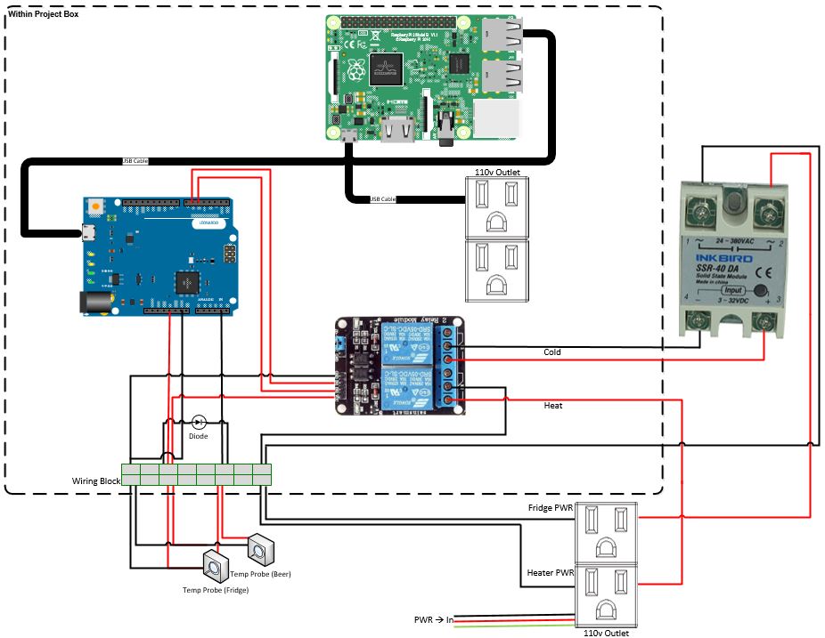
I've added a few labels for clarification
*Note that I swapped out the Leonardo for my Uno (I didn't realize I had my old setup pictured)*
Cold_Circuit_Issues_v2.JPG
 
Lee: yes, to the pin limit and then total package limit, an open drain output could be used with a 5v pull-up resistor...

Cheers!
 
@H0phead I think you are making it more difficult than it needs to be. I think that any time I need to get out a whiteboard to follow someone's wiring diagram, it's too complicated. Here's an updated basic diagram from the BrewPi Remix website:

1592336993061.png


Note that for the high voltage, the hot leg only is run through the relay. The common or neutral (which is grounded anyway in most locales) is not run anywhere except for the outlet. I'm not sure what you have there will work.

Then for your cool side, the same thing applies. You will run your hot leg to one side of your SSR (1) and then the other side (2) will go to the hot side of the outlet. In the diagram I've posted, run the jumper from NC on the first relay up to the SSR (1) instead of the second relay, and the red/hot leg to the SSR (2) - that will prevent both from coming on at the same time. I think heat and cool might be reversed in the diagram, but you can figure that part out.

Now you have the relay directly controlling Heat, and the SSR controlling Cool (with nothing controlling the SSR yet.) Run whatever pin you are using to control cooling to the low side of the SSR (3) and then run the other side (4) to ground.

Now when you set up the Heat control point, it will be the typical "inverted" and the Cool will be "non-inverted."

... at least I think I have all that right. :)

ETA: There's a reason why I leave this to the experts, but this is what I mean (I think):

1592338382910.png
 
Last edited:
Status
Not open for further replies.
Back
Top