HOWTO - Make a BrewPi Fermentation Controller For Cheap

Homebrew Talk - Beer, Wine, Mead, & Cider Brewing Discussion Forum

Help Support Homebrew Talk - Beer, Wine, Mead, & Cider Brewing Discussion Forum:

This site may earn a commission from merchant affiliate links, including eBay, Amazon, and others.
Status
Not open for further replies.
It totally works… you just have to separate the other 4 wires from the rj45 and connect them directly to mains voltage on either end.
*Sarcasm*
 
Hi guys. I have tried to search this thread, but to no avail. Simple question: is it possible to make the Arduino Uno communicate with the web server, in my case a VM on a NAS, over ethernet rather than USB using, for instance, a Ethernet Shield W5100? My NAS is in another room and I already have RJ45 sockets in my fermentation room.

If that shield can be run in a "transparent" mode such that the Uno still thinks the world is a serial port, it should work. Some of us are using esp8266 wifi-serial bridges to link Unos with BrewPi hosts, and that works because the Uno still "speaks serial" and the esp8266 does all the heavy lifting...

Cheers!
 
day_trippr and everyone else...

I realize I'm asking a lot, but my 10 year old son is really enjoying learning about electronics and soldering projects. So while we wait for parts from China for our BrewPi build, I thought he and I could take a stab at designing a PCB board based upon day_trippr's protoshield build.

Can you take a look at the attached schematic and let me know if I'm on the right track before we start tackling routing stuff on the board? This is my first attempt at a PCB board and this isn't an entry level board, so any help is very much appreciated.

Obviously, if I get this thing to work in the end, I'd be happy to share the PCB files here for anyone who's interested in printing up a board instead using the prototype. They are printed in three's and I only need two, so I'd even be happy to send day_trippr or anyone else my extra board for free in case you're looking to build another minion. I'll also document the build for those who are interested.

On the schematic, I left off the LEDs and the panel switches. The rest are intended to be separate male header pins for all of the optional projects on the BrewPi. I was going to silkscreen in info to help me remember where to hook everything up.

Thanks in advance for any guidance you can give!


https://drive.google.com/file/d/0BwakCoACNDsmcEhTV1d2Ujhnd28/view?usp=sharing
 
If that shield can be run in a "transparent" mode such that the Uno still thinks the world is a serial port, it should work. Some of us are using esp8266 wifi-serial bridges to link Unos with BrewPi hosts, and that works because the Uno still "speaks serial" and the esp8266 does all the heavy lifting...

Cheers!

Cool. I don't care whether its wifi or wired ethernet, as long as I can avoid USB. Thanks a lot for pointing me in the right direction :)
 
turns out my problems started when the USB ports' availability thru VirtualBox on the laptop crapped the bed

ports work fine in Windows 10, can use the mouse in VBox (the pointer disappears sometimes), but the Arduino/BrewPi port is crapped out, no USB devices are available for use

happened to have the Windows 10 PC I first used to hook up & test the BrewPi, but couldn't use it in the brew lab because 1) no wired Ethernet in the basement & 2) no monitor for it

well, both issues have been rectified and BrewPi is happily back up and running, in plenty of time for my BoP next Sunday at Brew LoCo.

thanks again, guys!
 
[...]Can you take a look at the attached schematic and let me know if I'm on the right track before we start tackling routing stuff on the board?[...]

Ok, I reviewed the Eagle schematic against my latest shield schematic. Other than having the 16-pin LCD connector sectioned as 1-12 and 1-4 (with 1-4 corresponding to 13-16), and the lack of the p-channel FET for the backlight dimming function (and the bits for the panel LED support) it looks to be an accurate copy.

I would recommend adding the p-FET, perhaps as an option with a wire jumper around it if the user opts not to install it. I have all my minions using the backlight dimmer function and prefer it to having them constantly glowing.

Otherwise I think you're good to get into layout...

Cheers!

I read the entire LCD add on thread a couple of times and I totally forgot that on page 15 or so you added the p-FET. I've modified the schematic to include it. I also changed out the 12 and 4 pin headers for the LCD to a 16 pin header. I looked and looked last night but couldn't find that 16 pin header. In literally 30 seconds this morning with a clear head, I found it.

As for the LED pull-ups, I couldn't figure out how those were wired in because I believe some of the wiring is built into the protoshield that you are building on. How would I add that as an option to fully replicate the protoshield?

https://drive.google.com/file/d/0BwakCoACNDsmUTFLTGlnTWVfZjA/view?usp=sharing
 
The LEDs on my minions are derived from a Love TSS2 implementation I did before BrewPi ever arrived on the scene.

love_tss2_front.jpg

I provided individual SPST/Center Off switches for both the Heat and Cool functions, with each switch selecting the AC mode (ie: either TSS2 controlled AC, Always On, or Always Off). This proved to be so useful that I did something similar with my BrewPi minions, except I used DPDT/Center Off switches, with one half of each switch controlling the AC mode for the function, and the other half of each switch controlling the state of the associated LED.


minion_upgrade_02.jpg

Here's the wiring scheme...

ac_power.jpg

I located the two "pull-up" resistors (actually, current limiting resistors in the 200-300 ohm range) on my shield design because it's the handiest place for them. Wrt a pcb layout, they're trivial, and it's always easier to have something in etch that's not used than it is to wish you had something in etch ;)

Cheers!
 
The LEDs on my minions are derived from a Love TSS2 implementation I did before BrewPi ever arrived on the scene.

I provided individual SPST/Center Off switches for both the Heat and Cool functions, with each switch selecting the AC mode (ie: either TSS2 controlled AC, Always On, or Always Off). This proved to be so useful that I did something similar with my BrewPi minions, except I used DPDT/Center Off switches, with one half of each switch controlling the AC mode for the function, and the other half of each switch controlling the state of the associated LED.


Here's the wiring scheme...

I located the two "pull-up" resistors (actually, current limiting resistors in the 200-300 ohm range) on my shield design because it's the handiest place for them. Wrt a pcb layout, they're trivial, and it's always easier to have something in etch that's not used than it is to wish you had something in etch ;)

Cheers!

I updated the schematic to add the LED pull-up resistors. You're right that it is better to add those now and not wish I had later on. As far as the rest of the switch wiring, I can use the female stacking headers to add the switches later if I understand it correctly.

I took a stab at the layout. I've attached links for the layout and the schematic. Two questions. First, the MOSFET is surface mounted. Did I get the soldering pads right on the layout? I can't tell.

Second, on the relay card header, it doesn't matter which of the two i/o pins are hot or cold, correct? It is either a matter of swapping the wires or a software setting if I have the card labeled incorrectly, right? Does that make sense?

Don't laugh at my routing. It was more difficult than I figured it would be.

https://drive.google.com/file/d/0BwakCoACNDsmNjRHOC1hZm1qb2s/view?usp=sharing
https://drive.google.com/file/d/0BwakCoACNDsmbnhERGhURlc2SWM/view?usp=sharing
 
ok so i am back on this thread again. honestly I gave up on this build, because the software was just too complicated for me.

Now NOOBS is downloadable and I can forsee this new project in the future. I knew it was a matter of time when people smarter than me would figure something like this out and put it together in a software package.

So I have read about half of this thread, thats how exiceted I was at the start, so my question is.......... is the hardware configuration the same for this build as it is on the first page? I remember seeing something with a minor tweek somewhere before half this thread.
courious minds want to know
 
First off noobs has been downloadable for like 5 or 6 years now, maybe more. secondly if you just came to this forum then you'd see the last 20 pages or so talking about how different the install is from the op and the new wiki links that fuzze has put together
 
ok so i am back on this thread again. honestly I gave up on this build, because the software was just too complicated for me.

Now NOOBS is downloadable and I can forsee this new project in the future. I knew it was a matter of time when people smarter than me would figure something like this out and put it together in a software package.

So I have read about half of this thread, thats how exiceted I was at the start, so my question is.......... is the hardware configuration the same for this build as it is on the first page? I remember seeing something with a minor tweek somewhere before half this thread.
courious minds want to know

The hardware is the same, there are a few changes to the install procedure documented on the Wiki at the top of the first post.
 
edit: I was able to change the /var/www/html to /var/www and finished the install. I received the message to enter the IP address into the web interface. I did the update sudo python updater.py and recived the message ***Done updating BrewPi****. But when I go to the Rpi IP address I get Not Found.


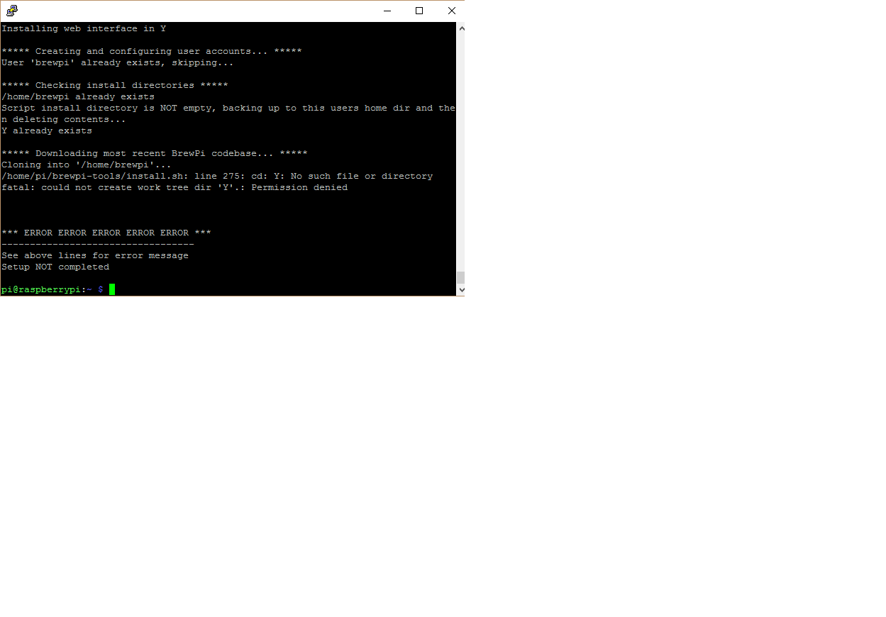
I have been working on this over the weekend and keep getting an error message when doing the automated install.

When the process gets to Downloading most recent BrewPi Codebase it gets an error stating no such file or directory.

Has anyone run into this before?

Rpi Error.png
 
edit: I was able to change the /var/www/html to /var/www and finished the install. I received the message to enter the IP address into the web interface. I did the update sudo python updater.py and recived the message ***Done updating BrewPi****. But when I go to the Rpi IP address I get Not Found.


I have been working on this over the weekend and keep getting an error message when doing the automated install.

When the process gets to Downloading most recent BrewPi Codebase it gets an error stating no such file or directory.

Has anyone run into this before?

It appears somehow you actually entered in Y as a directory to install things. You can see on the very first line its installing the Web interface into a directory named Y.

When you run these scripts simply hit enter when they ask you what path to install into and it uses the default. The default is /home/brewpi and /var/www for the webpage stuff. Only answer Y/N if it explicitly asks for those, in this case you entered Y when it was asking you for a directory to install to.


Ok. So if I do a reinstall that will solve the issue?
 
It appears somehow you actually entered in Y as a directory to install things. You can see on the very first line its installing the Web interface into a directory named Y.

When you run these scripts simply hit enter when they ask you what path to install into and it uses the default. The default is /home/brewpi and /var/www for the webpage stuff. Only answer Y/N if it explicitly asks for those, in this case you entered Y when it was asking you for a directory to install to.

That did it!

Thank you! Off to break more things.:mug:
 
Just wondering,

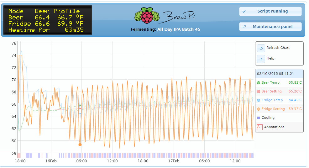
On my chart it shows different colors on the bottom

For cooling it starts out violet and then changes to blue/purple
For heating it starts out pinkish and then turns red

Are the off colors the waiting periods and the blue red the actual time on or is that indicating a ramping of temp while running?

(He said pinkish)

if you run your cursor along the lines, you can see what was happening at that point along the timeline by looking at the Date/Time box on the right

there's a STATE monitor in there too, which will explain those colors. violet and pinkish for waiting to cool/heat, respectively. the blue/purple and red are for actual cooling and heating
 
I've searched (this thread and The Google), and haven't found a 'yes' (well, or a no) answer....

Has anyone done any work on modifying the BrewPi automated installer (http://docs.brewpi.com/automated-brewpi-install/automated-brewpi-install.html) to work with multiple fermentation chambers?

It looks like a simple shell script, and doesn't look like it would be that difficult to modify it to include the differences from http://diybrewpi.wikia.com/wiki/Multiple_Fermentation_Chamber_Control_with_BrewPi
 
Anybody got any general wiring tips? I can't get my temp probes to show up, I'm using a connector like in the second schematic and I've wrapped the necessary wires around the resistor. With the other ones I've twisted them together before screwing them down in the connector. Is this the correct way to use a connector and resistor? I've checked the amazon listing where I bought the probes and they tell you which wire is which so I don't think its that. At a loss here :confused:
 
For the temperature probes I suggest you get one working first then add the others.

There are two parts to the connection. The first is on the 'controller' side. There are three connections, +5V, Data and Ground (0V). The resistor goes from Data to +5V. You only need one resistor.

The second part is the sensors themselves. They are strung out on parallel wires. Basically, each one gets a connection to +5V, Data and Ground. Make sure you get the pins the right way round.

If you can get a single sensor working then you can get several in parallel working (with only one pull-up resistor).

Thanks for replying so quickly, I'll try just the one tonight. Just out of interest, when you twist the wires together from the two sensors and stick them in the same slot in the controller, then have one wire going from the controller to the Arduino, this one wire can still separate out the two signals and the Arduino can understand it as two? Such a stupid question but this is my first time wiring anything and its interesting that the two wires can be distinguished after being hooked up this way.
 
Thanks for replying so quickly, I'll try just the one tonight. Just out of interest, when you twist the wires together from the two sensors and stick them in the same slot in the controller, then have one wire going from the controller to the Arduino, this one wire can still separate out the two signals and the Arduino can understand it as two? Such a stupid question but this is my first time wiring anything and its interesting that the two wires can be distinguished after being hooked up this way.

yes, it can!

Each temp probe has a unique 64-bit serial number to distinguish each individual probe
 
Anybody got any general wiring tips? I can't get my temp probes to show up, I'm using a connector like in the second schematic and I've wrapped the necessary wires around the resistor. With the other ones I've twisted them together before screwing them down in the connector. Is this the correct way to use a connector and resistor? I've checked the amazon listing where I bought the probes and they tell you which wire is which so I don't think its that. At a loss here :confused:

I just want to make sure you realize that the two connections opposite eachother on the wire block are connected together, thats the point of them.

One wire goes in one side, and you can then twist up your outputs together and put them in the other side to screw down.. I wasnt sure if that was obvious or not from your comment. Also double check the color stripes on your resistor, more than a few people have installed 47k or 470 ohm resistors on accident.
 
I just purchased a fermenter with internal coil. I have setup my mini fridge with a water bath, exchanger,heater and pump to supply cooling water to the coil. I have my brew pi fridge sensor in the water bath. I am fairly happy with the control but I think I can do better. Any suggestions on tuning the PID loop?
Thanks
Ken

Cooler graph.PNG


Fine graph.PNG
 
In a setup like that you might actually get better performance out of Fridge constant mode? Keep your fridge(and coil) at the set point. Right now i think its battling to get your beer to the setpoint because your fridge sensor is responding too fast? It seems to be cycling a lot and having problems trying to equalize the fridge temperature.
 
As a note I run the pump constant so the system behaves more like a fermenter in a chamber.
I am reluctant to use the constant fridge set point. In watching my other ferments I have seen an 8 or 9 degree difference between fridge and beer temp at the peak of fermentation. I could try in constant beer mode to see if it hones in a little closer.
I have a also thought about using as little water as possible to keep it from having a fly wheel effect with the mass of the water.

But if your running the pump constantly through your coil then your beer temp will always be the temperature of your fridge water correct? Or it will be within a small lag time...

When your fermenting beer warms up, it warms up the liquid in the coil which in turn heats your water jug, which your fridge corrects for by chilling, which chills your coil and your beer to compensate.

Your basically creating a HERMS loop like you'd use for holding mash temperature in a 3 vessel HERMS brewing setup. To hold your mash at a set point you dont measure the mash temperature, you set your HLT at a setpoint and pump your wort through the coil in the HLT which brings your wort to temperature and holds it there through heat transfer.

In this case your not actually pumping your wort through the coil, but the same principles should apply? In your case I think your not trying to control the beer temperature necessarily, by controlling the temperature of the fridge your controlling the temperature of the water in your coil, which controls your beer temp.

Hopefully that makes sense to someone :D
 
Just wrapping my head around this at this point and attempting to lay out a plan. Would an XP machine from around 10 years ago(512 Mb RAM) qualify in the old PC department to run the web server or is that too ancient? I have access to a bunch of old beat up xp machines I can re-purpose however I want, I just want to know if it would be a waste of time or if the OS would run on something that old.
 
It should run just fine i would assume? The hardest part will be getting Debian on the machine as some of those really old machines sometimes cant do USB boot for installs so you'd have to burn a DVD or something to install.
 
The net install image burned to a DVD is how I installed Debian wheezy on a 10+ year old XP laptop. It is working really well running 3 instances.

I wouldn't think a desktop computer would be much different, except that it may not have a wifi connection and would need a CAT5 connection to the Internet.
 
I don't plan on having it connected to the internet once everything is running.
 
I don't plan on having it connected to the internet once everything is running.

If you use the net install as i suggested, you'll need internet access to install the operating system. Additionally, You'll need network access unless you plan on having a permanent monitor and keyboard attached. Or want to attach them every time you want to check it's status.

In my opinion, the beauty of the system is being able to monitor and adjust the fermentation from any web browser on your home network.

Yeah I plan on the install and config to be done before I move it to the brewhouse, but network access there isn't feasible unless I add a wifi dongle, which I am not planning on at this time. I may run a cable to an old crt TV for monitoring through a converter. I just wanted to make sure the old PC wasn't too much of a dinosaur.
 
I was going through the dashboard and the beer profile option. Is there a way to upload several different profiles at once or do we need to create a profile one at a time?
 
Yeah I plan on the install and config to be done before I move it to the brewhouse, but network access there isn't feasible unless I add a wifi dongle, which I am not planning on at this time. I may run a cable to an old crt TV for monitoring through a converter. I just wanted to make sure the old PC wasn't too much of a dinosaur.

The internet connectivity is nice though so you can view it anywhere at your house but other than that its not necessary assuming your having it hooked up to a screen with keyboard/mouse so you can change the settings and view whats happening.
 
Has anyone tried to set up a BrewPi with a Cool Zone from gottabrew.com? I don't see any inherent reason why the BrewPi software should not work. Essentially, there would be only 1 temperature probe (the beer), a heater, and a chiller. There is no fridge, so there is no fridge temperature probe.

Thanks,
-Matt
 
Status
Not open for further replies.
Back
Top