• Please visit and share your knowledge at our sister communities:
  • If you have not, please join our official Homebrewing Facebook Group!

    Homebrewing Facebook Group

HOWTO - Make a BrewPi Fermentation Controller For Cheap

Homebrew Talk

Help Support Homebrew Talk:

This site may earn a commission from merchant affiliate links, including eBay, Amazon, and others.
Status
Not open for further replies.
I've got my BrewPi set up exactly as FuzzeeWuzzee laid out in the OP and it's almost all up and running -- except getting BrewPi to recognize my temperature probes (I have a feeling my splicing isn't quite up to par; should I use a breadboard?).

My main question is about the wire gauges going to/from the relay. I have a GE 7 cu. ft. chest freezer I picked up on Craigslist. Is 16 or 18 AWG thick enough to support the energy that this freezer is going to draw? The connectors on the Sainsmart relay are too small for 14 AWG, but 18 AWG fit well. I haven't tried 16 AWG. (I'm referring to stranded wire).

This is my first time working on a project like this and I just really don't want to burn the house down. Thanks for this awesome guide!

EDIT: After doing a little research, it looks like the freezer draws 1.7 amps under normal operation, so 16 or 18 AWG should be fine, right?
 
Let me know how it works out for you.

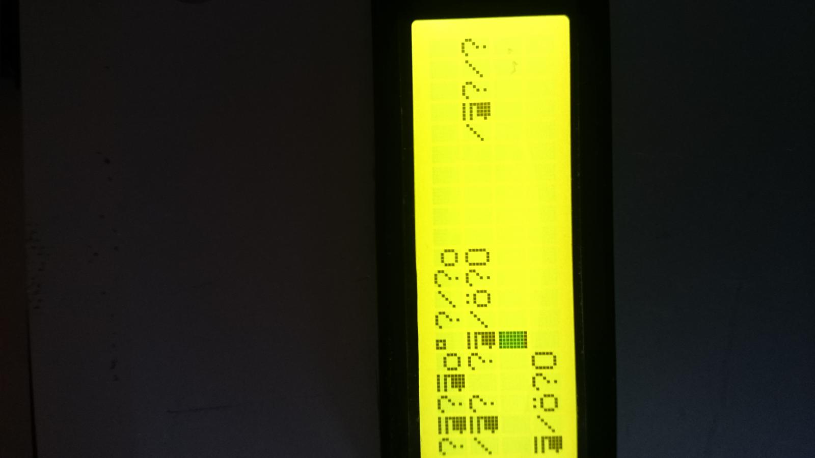
It seems that i have located the source of the problem.

I installed the SSRs today and still had the display errors.

I deconnected everything but a 5V power supply from the PCB and made some tests.

And i could not belive it:

The circuit is so sensitive to RF that even a nearby (2-3cm) light switch switched on and off can make it go haywire. And this with only a power supply connected!

It seems that the PCB acts like an antenna and the switch register is very sensitive to the spikes produced.

So now im really out of options :(

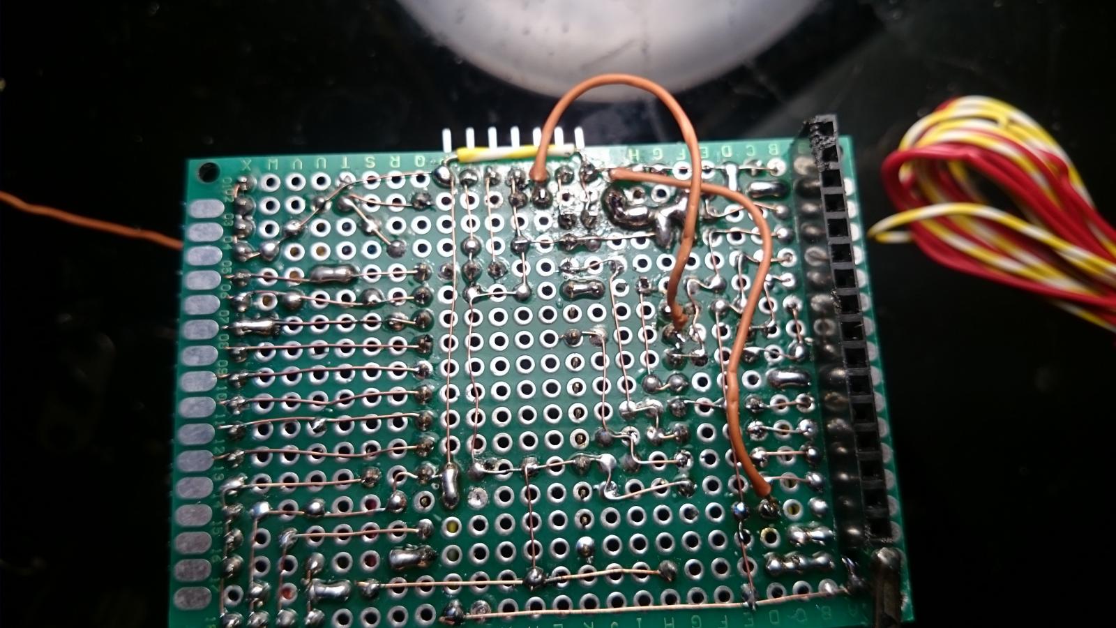
DSC_0637.jpg
 
Well that ain't right :(

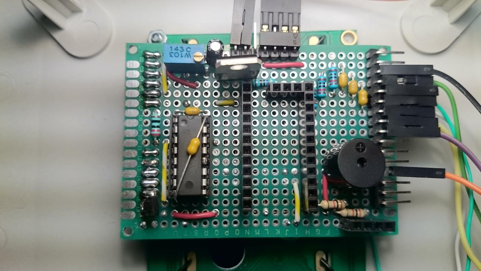
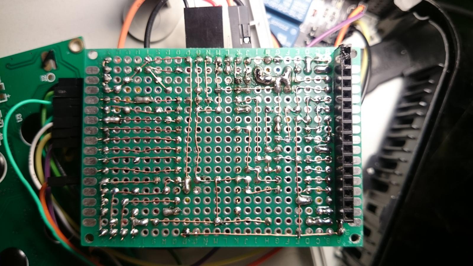
Can you remove everything from your shield and post good pictures of each side?

Cheers!

Thank you day_trippr, you are doing alot for this community.

I made 4 shields and all of them have it :(

DSC_0643.jpg


DSC_0642.jpg
 
I'll go over that in greater detail tonight, but right now the power and ground distribution looks like the prime candidate for noise-catching.

I'd take one your four boards and find a way to connect power and ground straight from that header to the IC. Fly over everything else with point-to-point wires and see what happens...

Cheers!
 
Could it be the piezo buzzer?

I have 3 other boards without buzzer but they have the lcd error.

@day_trippr
What if i would solder a 5V power source directly to the 74HC595 VCC and GND would that also be a sufficent test?

Also, the pro mini has 3 GND points, i have connected all of them should i just connect one?

Screenshot 2015-02-26 21.42.12.png


Screenshot 2015-02-26 21.42.51.png
 
I'm far from an electrical wizard, but would a possible solution be to put it in your case there and shield the entire interior(or exterior) of the case with aluminum foil which is redundantly connected to ground or the like to mitigate the external noise getting to it?

Its very ghetto but it may keep it the noise out, thats assuming the noise isnt coupling to the power itself outside of your box in which case you could just use some ferrite bead's around your cable to hopefully reduce that.
 
[...]What if i would solder a 5V power source directly to the 74HC595 VCC and GND would that also be a sufficent test?

Also, the pro mini has 3 GND points, i have connected all of them should i just connect one?

All ground pins on each device need to be connected to the common ground somewhere.

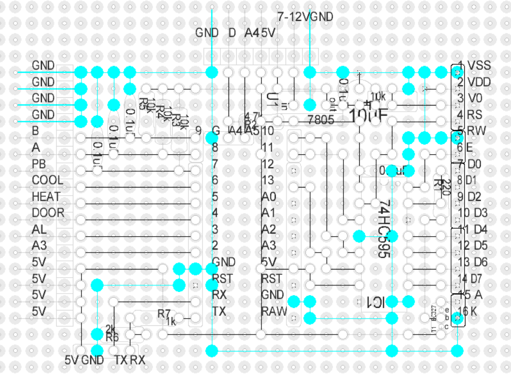
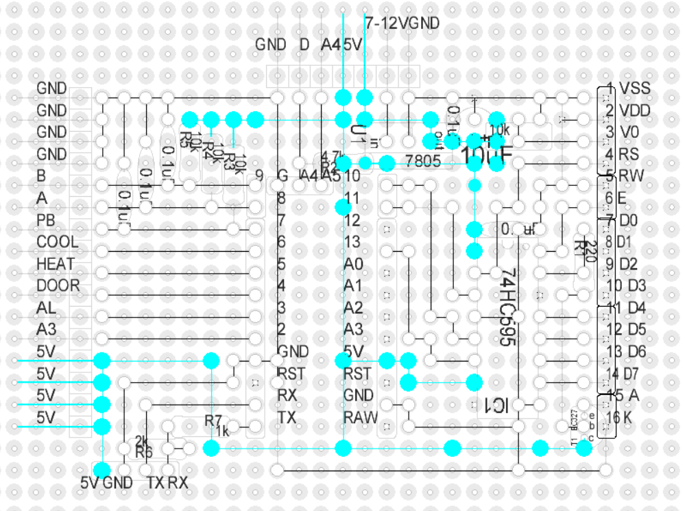
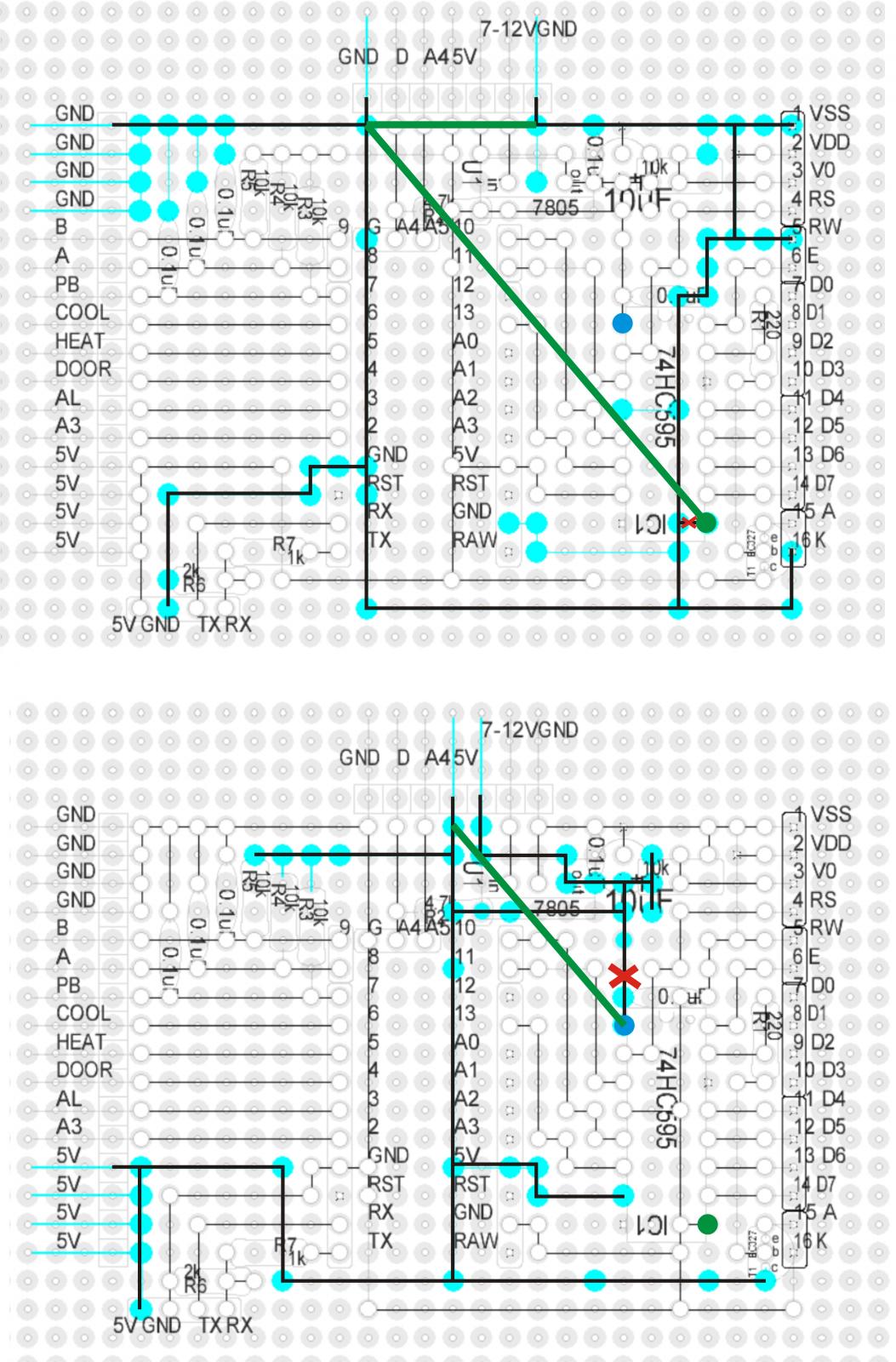
So here's what I'm thinking so far. Note that I tried to follow the GND and 5V distribution and high-light their major arteries. If I missed or crossed connections let me know.

- In the first diagram in the middle of the north edge there are apparently two header pins for ground - far right and far left. I can't tell if they're tied together at the headers, but they should be.

- Also, how many 5V connections to the board are there? In the second picture it looks like there are two header pins, but it's hard to tell if they're connected together on the board. If there are two pins, they should be wired together, again, right at the headers.

- How does the LCD get VCC on its pin 2?

- Are you using that 7805 for anything related to the shift register?

- I would isolate the power and ground connections to the shift register IC from the existing distribution. I tried to show a cut on the ground and another on the power diagrams.

Then connect them directly to the header pins using short wires (shown in green). Make sure to include at least one capacitor at IC pin 16 (VCC) to ground, using as short leads as possible.

- You should have capacitors across the headers from power to ground as well. Value for these bypass caps is optimally .1uf but you could go up or down an order of magnitude.

See if that changes the behavior at all...

Cheers!

doomy86_shield.jpg
 
So upon further review the good part is I'm loving the signal connectivity - nice short "traces" point to point between the Arduino module, the shift register and the LCD. I have to believe the noise catcher is the power and ground wiring by elimination.

Also I think I can see what the 7805 would be doing - if you were using it.
My guess is you're not...

Cheers!
 
So upon further review the good part is I'm loving the signal connectivity - nice short "traces" point to point between the Arduino module, the shift register and the LCD. I have to believe the noise catcher is the power and ground wiring by elimination.


Also I think I can see what the 7805 would be doing - if you were using it.

My guess is you're not...


Cheers!


He's got 7to 12v coming in and regulating down to 5 for the arduino.

Looks like it's missing a 1uF on the output side to ground? May be catching some noise there and going straight to vss
 
While I appreciate the attempt to school me on 3-terminal linear regulator applications...

"I deconnected everything but a 5V power supply from the PCB and made some tests. "

So, you see, while there's a linear regulator with its output wired to the 5V distribution on the board, he wasn't using it while debugging his system.

And, let's be careful out there....

Cheers!
 
While I appreciate the attempt to school me on 3-terminal linear regulator applications...


"I deconnected everything but a 5V power supply from the PCB and made some tests. "


So, you see, while there's a linear regulator with its output wired to the 5V distribution on the board, he wasn't using it while debugging his system.


And, let's be careful out there....


Cheers!


Lol. I debated posting that. I kept thinking. Hmmmm...... He designed a 10 layer pcb the size of my thumb. He's helped every electronics related post on this forum? How does he not know what a 7805 does?

Didn't catch that he disconnected earlier. Haha.
 
All ground pins on each device need to be connected to the common ground somewhere.

So here's what I'm thinking so far. Note that I tried to follow the GND and 5V distribution and high-light their major arteries. If I missed or crossed connections let me know.

- In the first diagram in the middle of the north edge there are apparently two header pins for ground - far right and far left. I can't tell if they're tied together at the headers, but they should be.

They are not tied toghether, im soldering a cable to connect them right now.

- Also, how many 5V connections to the board are there? In the second picture it looks like there are two header pins, but it's hard to tell if they're connected together on the board. If there are two pins, they should be wired together, again, right at the headers.

There are 5V outputs on every side, 4 on the bottom left, 1 for the bluetooth module and 1 for the 1-wire connection.

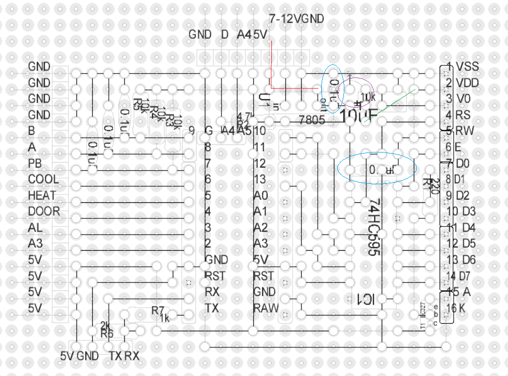
On the top of the board is a 5V input right next to the output for the 1-wire. I did not tie them together at the header because i wanted to get the input trough the 0.1 and 10uf cap first. (Red on the schematic)

- How does the LCD get VCC on its pin 2?

There is a topside jumper wire marked in green on the schematic.

- Are you using that 7805 for anything related to the shift register?

I have 3 power supplys (all of them get the display errors):

9V switching (brewpi1) uses the 7805 @ 7-12V input pin
9V transformer (brewpi2) uses the 7805 @ 7-12V input pin
5V switching (testing) directly connected on 5V input pin

- I would isolate the power and ground connections to the shift register IC from the existing distribution. I tried to show a cut on the ground and another on the power diagrams.

Then connect them directly to the header pins using short wires (shown in green). Make sure to include at least one capacitor at IC pin 16 (VCC) to ground, using as short leads as possible.

- You should have capacitors across the headers from power to ground as well. Value for these bypass caps is optimally .1uf but you could go up or down an order of magnitude.

I try that right now.

I already have 0.1uF(blue circle) and 10uF (violet circle) cap right after the 7805 for input filtering. There is another 0.1uF right at the shift register VCC pin (blue circle) for decoupling.

See if that changes the behavior at all...

Cheers!

@andrewmalizia
Yes, normally im using 9V power supplys, the 5V is just for testing.
There are 0.1 and 10uF caps on the out side of the 7805.

@FuzzeWuzze
You are right, but then i would have to seperate the mains part with relays and Power supply from the low voltage part. Maybe that is something i have to consider.

Thank you all again for your help i would be lost on this issue without you.

Screenshot 2015-02-27 09.05.52.png
 
I made all the changes you proposed but the EMF problem is still there..

I can trigger the display errors by switching the transformer in my box on and off.. or just by plugging in and out a notebook charger near the PCB..

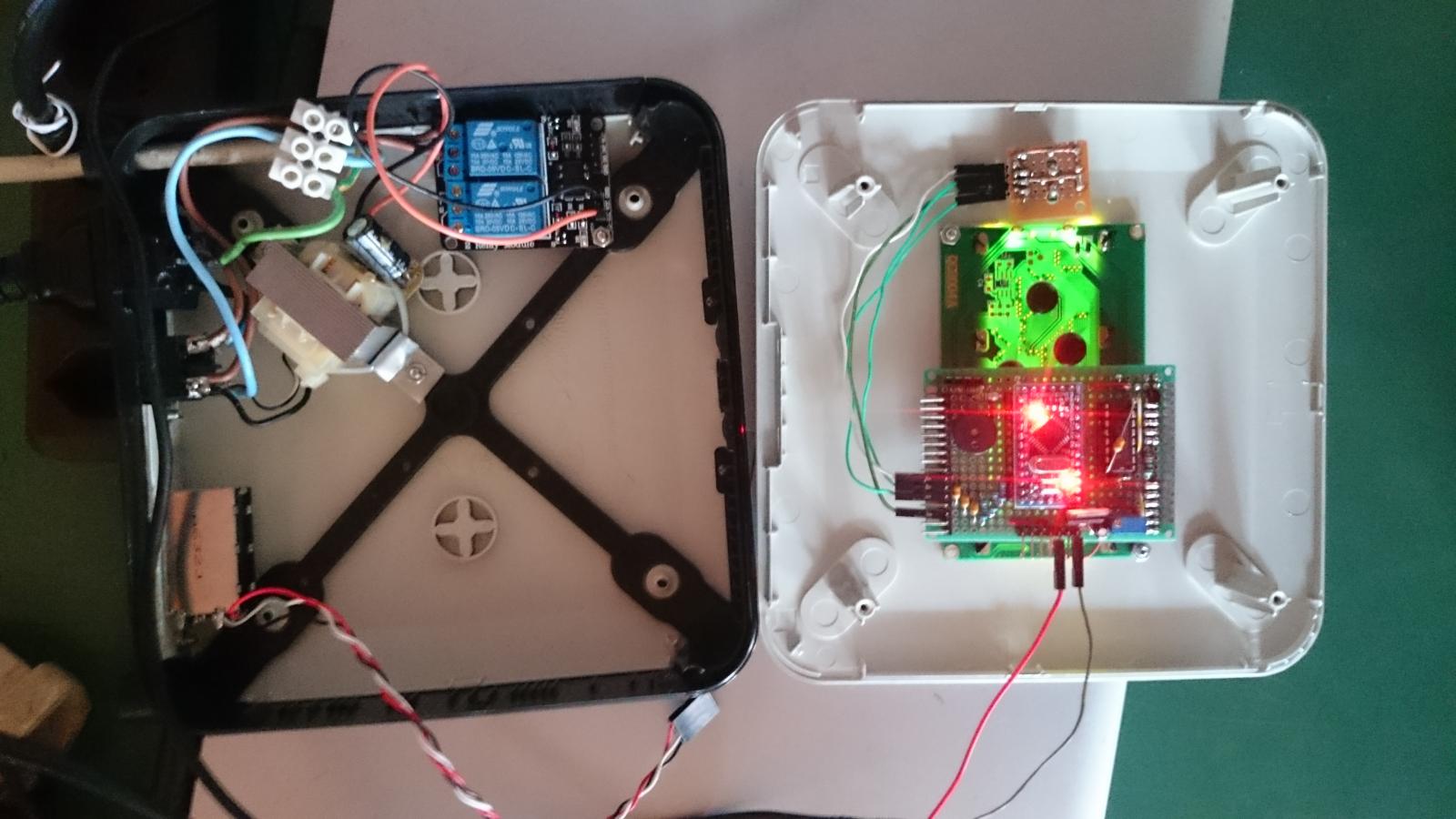
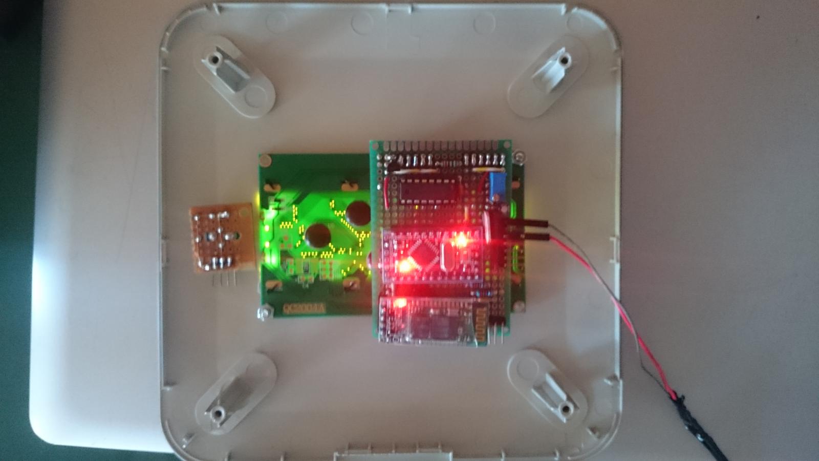
You can see my test setup on the images..

1. There is just a external 5V supply connected to the PCB.
2. I put the box together and flip the switch behind on and off, 3 times is usualy enough to produce the unwanted result..

DSC_0646.jpg


DSC_0649.jpg


DSC_0650.jpg


DSC_0651.jpg
 
Long shot but have you tried running it off a battery. Could go 12v with a buck converter
Troubleshooting. Lol
 
Maybe he lives too close to the power lines.... Put on ur tinfoil hat! The govments tryin to infiltrate ya fermentators!
 
fwiw, "short" would mean "almost has to stretch to connect".

Grasping at straws now, but you might try actually lengthening the wires for the shift register SCLK and RCLK (IO 13 to IC pin 11, and IO 10 to IC pin 12, respectively) to see if anything changes. One way or the other the most likely failure is the shift register getting whacked, and those are the two inputs that could do it, with the SCLK being the most likely...

Cheers!
 
@doomy86

have you tried putting the 7-12 into the raw input on the pro mini and letting it regulate the board to 5v?
 
Long shot but have you tried running it off a battery. Could go 12v with a buck converter
Troubleshooting. Lol

I could try that, but it is not a solution. It would only further prove the AC noise/EMF problem.

day_trippr said:
Grasping at straws now, but you might try actually lengthening the wires for the shift register SCLK and RCLK (IO 13 to IC pin 11, and IO 10 to IC pin 12, respectively) to see if anything changes. One way or the other the most likely failure is the shift register getting whacked, and those are the two inputs that could do it, with the SCLK being the most likely...
Cheers!

Thank you, yes im going to try that. What about more filter/decoupling caps, where would you put them?

andrewmalizia said:
have you tried putting the 7-12 into the raw input on the pro mini and letting it regulate the board to 5v?

Good idea, never tried it im going to post the results.

Just found the following post:

http://forum.brewpi.com/discussion/409/lcd-display-errors

Elco says there:

A few months ago I had this issue too, but that was because the SS pin of the SPI was not set to output. An ignition spark from my gas stove would cause garbage on the display. This was fixed months ago though, so if you are using a 0.2 or later hex file you shouldn't have this issue.

The arduino pro mini has a few extra analog ports A6 and A7.. Could it be that they are configured as inputs and somehow causing the errors?
 
The arduino pro mini has a few extra analog ports A6 and A7.. Could it be that they are configured as inputs and somehow causing the errors?

Yes, I believe all arduino pins are inputs by default. You could always try putting a couple pulldown resistors on them and see what happens.
 
Model 2 is alive - and running everything wicked fast!

It's perched inside my backup BrewPints crate propped up by some strategically placed Pink Pearl erasers so it doesn't arc against the Model B underneath.

And lemme tell you, this puppy is stunningly quick!
Holy crap, before I thought to look the gui was up and running.
Launching desktop apps happens NOW.

Wheeeee!

These are priced at the recommended $35 locally which is so close to the B and B+ that you would be foolish to go cheap.
This thing frickin' FLIES through stuff that bogged the heck out of my B.

And as it's running the same card I pulled out of the B ten minutes ago, it's truly an apples-to-apples comparo...

Cheers! :mug:

More: RaspberryPints tap list updates in a blink.
No protracted repaint of the whole screen, no sitting there halfway updated then finally finishing.
After at least a dozen tests, it always seems to just update the keg volumes in place without anything else changing.
I'm loving this!

Fitting the Model 2 is gonna be a hella bitch though. I 'spect it's going to take most of tomorrow...

model2_is_alive.jpg
 
Model 2 is alive - and running everything wicked fast!

It's perched inside my backup BrewPints crate propped up by some strategically placed Pink Pearl erasers so it doesn't arc against the Model B underneath.

And lemme tell you, this puppy is stunningly quick!
Holy crap, before I thought to look the gui was up and running.
Launching desktop apps happens NOW.

Wheeeee!

These are priced at the recommended $35 locally which is so close to the B and B+ that you would be foolish to go cheap.
This thing frickin' FLIES through stuff that bogged the heck out of my B.

And as it's running the same card I pulled out of the B ten minutes ago, it's truly an apples-to-apples comparo...

Cheers! :mug:

More: RaspberryPints tap list updates in a blink.
No protracted repaint of the whole screen, no sitting there halfway updated then finally finishing.
After at least a dozen tests, it always seems to just update the keg volumes in place without anything else changing.
I'm loving this!

Fitting the Model 2 is gonna be a hella bitch though. I 'spect it's going to take most of tomorrow...

damn. i was hoping the review of the 2 wouldnt be so glowing.... now i need to order one... ugh...
 
Seriously, this thing is the balls.
And with all that, it runs at least 20°F cooler in my enclosure.

I have a system service that monitors the SOC temperature sensor and turns on a 40mm fan when it hits 135°F and shuts it off at 115°F. With the Model B the fan would cycle around every 15 minutes for about 60 seconds. With the Pi 2 it was never coming on.

I actually went on-line to find out if the new SOC still supported this function but couldn't find any info at all. Finally I just ran the script in a console and it was happily returning the temperature as slightly above 115°F.

I may ditch the fan now...

Cheers!
 
Hey guys,

So, apparently I came to BrewPi late for the DIYer... Elco is now offering the Spark model which is no longer a DIY thing... I was excited about learning Arduino, etc. by doing my own shield kit. So instead of buying a Spark, I went down the road of building my own.

Elco stopped selling the Arduino Shield kit, and I can understand why. Supply chain management and endless support can't be fun. So, I'm happy to do this on my own, but need a little help in some areas. So here is where I'm at.

I didn't want to start from scratch and hard wire a PCB like this one: http://www.brewpi.com/do-it-yourself-brewpi-arduino-shield/ I followed this thread and found the eagle files for an early PCB. I had a few of these made up: http://1drv.ms/1BOCDiF

I've got everything soldered up and I've tested the Temp sensors and LCD independently with Arduino Sketches. LCD works, One wire temps work. Now to get everything going with the brewpi_avr.

So, I setup my PI, all good, but then when it came time to install the HEX on the Arduino is when I started seeing issues. My Shield isn't a REV-A or a REV-C shield, its what could be considered a DIY-Shield. I couldn't get the RevA hex or RevC hex to work right. So I started cracking the code.

I downloaded all the sourcecode from GitHub, install Atmel Studio and started figuring out how all this works. I added a config.h and set it to use the DIY shield.

Code:
#ifndef BREWPI_STATIC_CONFIG
#define BREWPI_STATIC_CONFIG BREWPI_SHIELD_DIY
 #endif

I compiled a new .hex file and uploaded it to my Arduino with the BrewPi web ui. The logs show this:
Code:
**** Arduino Program script started ****

Arduino Home /usr/share/arduino/

Settings will not be restored

Devices will not be restored

Checking old version before programming.

Found BrewPi v0.2.4, running commit 00000000, on an Arduino standard on port /dev/ttyACM0


Requesting old settings from Arduino...

Saving old settings to file oldAvrSettings-Mar-01-2015-08-48-45.json

Loading programming settings from board.txt

Checking hex file size with avr-size...

Program size: 25666 bytes out of max 32256

Programming Arduino with avrdude: /usr/share/arduino/hardware/tools/avrdude -F -e -p atmega328p -c arduino -b 115200 -P /dev/ttyACM0 -U flash:w:"brewpi_avr.hex" -C /usr/share/arduino/hardware/tools/avrdude.conf

result of invoking avrdude:

avrdude: AVR device initialized and ready to accept instructions

Reading | ################################################## | 100% 0.00s

avrdude: Device signature = 0x1e950f
avrdude: erasing chip
avrdude: reading input file "brewpi_avr.hex"
avrdude: input file brewpi_avr.hex auto detected as Intel Hex
avrdude: writing flash (25666 bytes):

Writing | ################################################## | 100% 4.95s

avrdude: 25666 bytes of flash written
avrdude: verifying flash memory against brewpi_avr.hex:
avrdude: load data flash data from input file brewpi_avr.hex:
avrdude: input file brewpi_avr.hex auto detected as Intel Hex
avrdude: input file brewpi_avr.hex contains 25666 bytes
avrdude: reading on-chip flash data:

Reading | ################################################## | 100% 3.95s

avrdude: verifying ...
avrdude: 25666 bytes of flash verified

avrdude done. Thank you.


avrdude done!

Giving the Arduino a few seconds to power up...

Back up in 5...

Back up in 4...

Back up in 3...

Back up in 2...

Back up in 1...

Back up in 0...

Now checking which settings and devices can be restored...

Checking new version: Found BrewPi v0.2.4, running commit 00000000, on an Arduino standard on port /dev/ttyACM0


Resetting EEPROM to default settings

Arduino debug message: INFO MESSAGE 15: EEPROM initialized

No settings to restore!

No devices to restore!

**** Program script done! ****

If you started the program script from the web interface, BrewPi will restart automatically

Mar 01 2015 08:49:12 New program uploaded to Arduino, script will restart
Mar 01 2015 08:49:19 Notification: Script started for beer 'My First BrewPi Run'
Mar 01 2015 08:49:30 Found BrewPi v0.2.4, running commit 00000000, on an Arduino standard on port /dev/ttyACM0

Mar 01 2015 08:49:35 Installed devices received: []
Mar 01 2015 08:49:35 JSON decode error: Expecting object: line 1 column 1 (char 1)
Mar 01 2015 08:49:35 Line received was: h:[D:{"logType":"I","logID":10,"V":[-1]}

Mar 01 2015 08:49:35 Cannot process line from Arduino: {"i":-1,"t":0,"c":1,"b":0,"f":0,"h":2,"d":0,"p":10,"a":"28DE243E060000A2","j": 0.000}D:{"logType":"I","logID":10,"V":[-1]}

Mar 01 2015 08:49:35 Cannot process line from Arduino: ,{"i":-1,"t":0,"c":1,"b":0,"f":0,"h":2,"d":0,"p":11,"a":"28A2B83F0600005E","j": 0.000}D:{"logType":"I","logID":10,"V":[-1]}

Mar 01 2015 08:49:35 Cannot process line from Arduino: ,{"i":-1,"t":0,"c":1,"b":0,"f":0,"h":1,"d":0,"p":13,"x":1}D:{"logType":"I","logID":10,"V":[-1]}

Mar 01 2015 08:49:35 Cannot process line from Arduino: ,{"i":-1,"t":0,"c":1,"b":0,"f":0,"h":1,"d":0,"p":12,"x":1}]

Mar 01 2015 08:49:42 Installed devices received: []
Mar 01 2015 08:49:42 JSON decode error: Expecting object: line 1 column 1 (char 1)
Mar 01 2015 08:49:42 Line received was: h:[D:{"logType":"I","logID":10,"V":[-1]}

Mar 01 2015 08:49:42 Cannot process line from Arduino: {"i":-1,"t":0,"c":1,"b":0,"f":0,"h":2,"d":0,"p":10,"a":"28DE243E060000A2","j": 0.000}D:{"logType":"I","logID":10,"V":[-1]}

Mar 01 2015 08:49:42 Cannot process line from Arduino: ,{"i":-1,"t":0,"c":1,"b":0,"f":0,"h":2,"d":0,"p":11,"a":"28A2B83F0600005E","j": 0.000}D:{"logType":"I","logID":10,"V":[-1]}

Mar 01 2015 08:49:42 Cannot process line from Arduino: ,{"i":-1,"t":0,"c":1,"b":0,"f":0,"h":1,"d":0,"p":13,"x":1}D:{"logType":"I","logID":10,"V":[-1]}

Mar 01 2015 08:49:42 Cannot process line from Arduino: ,{"i":-1,"t":0,"c":1,"b":0,"f":0,"h":1,"d":0,"p":12,"x":1}]

So this is where I'm stuck. I don't know why I'm getting these JSON errors. And I'm unable to add my devices.
Have any of you seen this before ? What code parses this JSON and what format is it expecting ?

Thanks,
Gavin
 
I don't know why I'm getting these JSON errors. And I'm unable to add my devices.
Have any of you seen this before ? What code parses this JSON and what format is it expecting ?

Thanks,
Gavin

Gavin,

I had problems programming my brewpi when I had more than one arduino attached to the host computer. I unplugged everything except the brewpi, reformatted, installed my devices, and set the brewpi. Then I plugged the other arduino back in and everything works properly on both devices.

This chain of events does not make a lot of sense to me, but it has occurred twice for me. YMMV

Cody
 
Its been talked about around 100 times or so on this thread. If you are using multiple arduinos on one pi you gotta use a powered hub or power each Arduino independently.
 
I'm pretty sure you could take a naked Uno and use the BrewPi gui to upload the hex file to it - as long as the script is stopped.

Remove the shield, reboot everything and try again.

I agree those errors look like classic "under-voltage" transport failures...

Cheers!
 
Just had a similar issue the other day with one of my bluetooth minions. I was powering it with a 6000mAh backup charger. Once the battery reached about 15% it couldn't support the nano and BT radio reliably. And I received almost identical errors like he posted.
 
I wasn't using multiple Arduinos, but just the USB power from the Pi. I added an actual powercord to my Arduino now, reprogramming, we'll see what happens...
 
Code:
Mar 01 2015 22:05:04 Notification: Script started for beer 'test'
Mar 01 2015 22:05:16 Found BrewPi v0.2.4, running commit 00000000, on an Arduino standard on port /dev/ttyACM0

Mar 01 2015 22:06:25 Installed devices received: []
Mar 01 2015 22:06:25 JSON decode error: Expecting object: line 1 column 1 (char 1)
Mar 01 2015 22:06:25 Line received was: h:[D:{"logType":"I","logID":10,"V":[-1]}

Mar 01 2015 22:06:25 Cannot process line from Arduino: {"i":-1,"t":0,"c":1,"b":0,"f":0,"h":2,"d":0,"p":10,"a":"28DE243E060000A2","j": 0.000}D:{"logType":"I","logID":10,"V":[-1]}

Mar 01 2015 22:06:25 Cannot process line from Arduino: ,{"i":-1,"t":0,"c":1,"b":0,"f":0,"h":2,"d":0,"p":11,"a":"28A2B83F0600005E","j": 0.000}D:{"logType":"I","logID":10,"V":[-1]}

Mar 01 2015 22:06:25 Cannot process line from Arduino: ,{"i":-1,"t":0,"c":1,"b":0,"f":0,"h":1,"d":0,"p":13,"x":1}D:{"logType":"I","logID":10,"V":[-1]}

Mar 01 2015 22:06:25 Cannot process line from Arduino: ,{"i":-1,"t":0,"c":1,"b":0,"f":0,"h":1,"d":0,"p":12,"x":1}]
The strange part here to me is, it seems the Arduino is returning data about it's sensors for the brewpi script to receive, it's like the json is in the wrong format or something?

How do I debug this? Kill the BrewPi cron job and run the BrewPi.py myself ? There are some testTerminal and util scripts, any of this help me ?
 
Try a different usb cord first. If that doesn't help restart everything.

It's weird that it's doing this without the error "could not receive version info from arduino"
 
Mar 01 2015 14:16:16 Notification: Script started for beer 'BrewPi2 Test4'
Mar 01 2015 14:16:28 Found BrewPi v0.2.4, running commit 2a6f7f05 build 40, on an Arduino standard with a revC shield on port /dev/rfcomm0

Why doesn't your log look something like that?
Are you still trying to use your home-cooked hex file?

Cheers!
 
I'll see if I can address all your questions, but right from the start, you are apparently comparing the original, Revision A BrewPi design to the current, Revision C BrewPi design.

Thank you so much, day_tripper, for taking the time to help me understanding the magic world of BrewPi diy'ing. I really appreciate this!

Thanks for clearing up the mix-up when comparing different versions of the shield. I've gotten the one from http://www.brewpi.com/wp-content/uploads/2012/09/BrewPi-Arduino-Shield.pdf, and wrongfully thought that it was a current one.

I've started building my BrewPi this weekend, and had it all working. Awesome feeling! Next step is to put it all in a proper case, with nice connectors and a fan.

A few questions remain:

[Talking about Rotary encoder] Not pins 0, 1 and 2, but 7, 8 and 9.
Very basic question: How to I identify which of the pins on a rotary encoder are PB, A and B?

You can add the door switch connection to AVR pin 4
Do you mean D4, or A4 (which is already used by the one wires) or another on the Arduino?


I have [a little fan] controlled by an RPi system process based on the SOC temperature reading. It may be overkill but that's kinda my thing ;)
Love this!
 
Avr pin D4 for door. The avr pins used by brewpi are:
D2
D4
D5
D6
A5

D3 goes to a buzzer if you want.

All the ports can be setup to control anything. Fridge, heater, fan, light, or as a door sensor. There is currently a bug in the code that kinda keeps you from changing the door pin from pin 4 or should I say, it doesn't list the door sensor under any of the other pins as an option.
 
Thank you so much, day_tripper, for taking the time to help me understanding the magic world of BrewPi diy'ing. I really appreciate this!

My pleasure, couldn't have you heading down the wrong road from the jump ;)

[...]Very basic question: How to I identify which of the pins on a rotary encoder are PB, A and B?

The encoder common is the middle terminal on the 3-terminal side. Wire either of the PB contacts on the 2-terminal side to the encoder common then connect that to ground. In the pic the purple wire (PB) connects to "digital IO 7", the blue wire ("Rotary A") connects to "digital IO 8", and the green wire ("Rotary B") connects to "digital IO 9". If you swap those encoder connections, digits will decrement when you rotate the encoder clockwise...

Cheers!

encoder_wiring.jpg
 
Thanks for this great work. A question if anyone can help me (I'm rather new at this). Instead of buying both temperature probes and relays, could I use the ones in a stc 1000? I have several around but I am planning to evolve to a controller such as this, with remote control + data logging.

I have seen that some logging can be done with an arduino + stc 1000, as shown here: https://github.com/matsstaff/stc1000-datalogger
But can I use the stc 1000 like this: use it as a temperature probe, shows the temperature in the display, gives the temperature data to the arduino so it can do its work, but re using the stc 1000 relays instead of using the wiring shown as standard in this post?
Any help would be appreciated, thanks in advance!
 
OK, I started a new brew yesterday and in checking my BrewPi logs this morning came across this. It's running fine just thought the error was odd.
File "/usr/lib/python2.7/dist-packages/serial/serialposix.py", line 485, in write
raise SerialException('write failed: %s' % (v,))
serial.serialutil.SerialException: write failed: [Errno 5] Input/output error
Mar 02 2015 03:00:01 Notification: Script started for beer 'Blues Brothers Ale'
Mar 02 2015 03:00:12 Found BrewPi v0.2.4, running commit 2a6f7f05 build 40, on an Arduino standard with a revC shield on port /dev/ttyACM0


Thanks
David
 
Status
Not open for further replies.
Back
Top