• Please visit and share your knowledge at our sister communities:
  • If you have not, please join our official Homebrewing Facebook Group!

    Homebrewing Facebook Group

GFCI Panel Help

Homebrew Talk

Help Support Homebrew Talk:

This site may earn a commission from merchant affiliate links, including eBay, Amazon, and others.
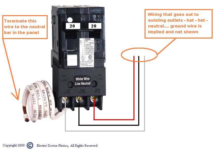
Your line in neutral has to go to the breaker. The load side is a seperate neutral FROM the breaker so it can monitor for faults. They cannot be tied together on the same bar. Your line-in neutral should be connected (wirenutted) to the pigtail on the breaker and the neutral bar (load neutral) should be tied to the neutral terminal on the breaker.

Good catch. That is it. I missed it through the wiring, but see it now that you mention it.
 
The line comes in on the pigtail. The load goes out on the terminal. Getting confusing...

2010-01-05_010629_GFCI_breaker_wiring_double_pole.JPG
 
Alright, tried Mxstar's version pre-edit and it didnt work :cross:

Don't have any 10ga nuts and I dont feel like soldering them so I'll have to try it again tomorrow. Thanks for the help everyone, hopefully it's an easy fix tomorrow. Who would have thought that posting a clearer picture would help find the solution? Magic.
 
Tie the pigtail from the breaker to the incoming neutral only. Tie the outgoing neutrals to the neutral terminal on the breaker.

Although, isn't this what I had done originally? The power in and pigtail went to the bus, the load neutral went to the outlet. Is there something special about these that require direct routing and the bus wont work?
 
It's hard to to tell, but I think you have 1 too many neutrals on the breaker. The pigtail built into the breaker should run to the neutral bus, the incoming neutral should run to the neutral bus, and the neutral on the outlet should run to the neutral bus not the breaker. Is the gfci tripping? Gfci' work by sensing an imbalance in current flow. Hard to say, but I think if you remove the neutral wire attached to the breaker/outlet and attach outlet/neutral bus it will work.
 
Sorry, I am not very clear tonight, just switched to night shift. I am out of it, and having hard time explaining things. I think this picture should help explain what we are trying to say.

search
 
Although, isn't this what I had done originally? The power in and pigtail went to the bus, the load neutral went to the outlet. Is there something special about these that require direct routing and the bus wont work?

If the bus is bonded YES. Sleep on it. It will all be clear in the morning;)
 
so as i understand it: you are turning the breaker on, it is not tripping but you are getting no power at the receptacle. if this is the case, i would say you have a bad breaker. with no load hooked up, the breaker won't trip, even if wired up incorrectly.

regarding the neutral, it appears correct in your photo. it should be hooked up by:

- connect incoming neutral to isolated neutral bar in spa panel
- connect gfci neutral pigtail to isolated neutral bar
- connect receptacle neutral to neutral terminal on the breaker (not the neutral bar)

there is no need to solder or wire nut anything. you can try wiring nutting the incoming neutral and pigtail neutral, to check if your neutral bar is not isolated but that won't matter right now anyway: with the breaker on and no load, you should still see voltage at the receptacle.

That's how I had it, yes. I'm thinking it's just a bad breaker as well. I have correct voltage at the feed lugs and then zip on the load side of breaker. I'm going to try Ischiavo's suggestions first though.
 
Your line in neutral has to go to the breaker. The load side is a seperate neutral FROM the breaker so it can monitor for faults. They cannot be tied together on the same bar.

Your line-in neutral should be connected (wirenutted) to the pigtail on the breaker and the neutral bar (load neutral) should be tied to the neutral terminal on the breaker.

Tie the pigtail from the breaker to the incoming neutral only. Tie the outgoing neutrals to the neutral terminal on the breaker.

It's hard to to tell, but I think you have 1 too many neutrals on the breaker. The pigtail built into the breaker should run to the neutral bus, the incoming neutral should run to the neutral bus, and the neutral on the outlet should run to the neutral bus not the breaker. Is the gfci tripping? Gfci' work by sensing an imbalance in current flow. Hard to say, but I think if you remove the neutral wire attached to the breaker/outlet and attach outlet/neutral bus it will work.


I disagree with the first two quotes and the red in the third. All clamp terminal connections to the breaker should be load conductors.

Line neutral should terminate on the "isolated/ungrounded" neutral bus bar. The breaker neutral pigtail terminates on that same neutral bus bar. The load neutral terminates on the neutral breaker clamp.

The result is that all load neutral current passes through the breaker and can be monitored.

I believe it is wired correctly. Please remember the symptoms. Breaker is NOT tripping, even with the test button. There is no voltage when the breaker is ON.

One thing I noticed is when running my multimeter on one power-in and one load I get 120v instead of 240v. Any idea what that's aboot?
You would need to identify exactly where that measurement is being taken to make any judgments.
 
I disagree with the first two quotes and the red in the third. All clamp terminal connections to the breaker should be load conductors.

Line neutral should terminate on the "isolated/ungrounded" neutral bus bar. The breaker neutral pigtail terminates on that same neutral bus bar. The load neutral terminates on the neutral breaker clamp.

The result is that all load neutral current passes through the breaker and can be monitored.

I believe it is wired correctly. Please remember the symptoms. Breaker is NOT tripping, even with the test button. There is no voltage when the breaker is ON.

electrically, there is no difference with tying the incoming neutral to the breaker pigtail and skipping the panel neutral bar altogether. wire the breaker load neutral terminal to the receptacle and be done. you could even wire the breaker load neutral terminal to the isolated neutral bar and then from there to the receptacle.

these 'funky' configurations are possible because this is a spa panel, which is little more than a single circuit panelboard. you wouldn't want to do this in a multi-circuit panel board since it would be difficult to wire-nut all the neutrals together. it is much more practical to wire the 'system' neutral to a bus and pick up all the branch circuit neutrals from there.

all that being said, i'm with you that the wiring in the photo is correct and reflects best practice (the technique that would be used in a larger panelboard). the key is that the breaker pigtail and load neutral not be directly connected to one another.
 
Ran to HD on my lunch break and they didnt have any of the same spa panels. Annoying. Guess I'll order another one online. Or maybe just spring for the in-line...
 
Or maybe just spring for the in-line...

i went with the 30 amp gfci breaker in my panelboard, even though that breaker cost more than a 50 amp spa panel. factoring in a 30 amp 'regular' breaker for the panelboard in addition to the spa panel and it was only a few bucks more to just get the 30 amp gfci. plus it is one less piece of equipment to mount, wire up, have the potential to malfunction, etc.
 
Yeah I could go that route too. I'm renting so would prefer not modifying the panel but we'll see, heh.
 
Alright, tried the wire nut and bypassing the neutral bar. Still no luck. Made sure all the wires and everything was set properly, still no voltage on the load side of breaker. Think it's borked.
 
Alright, tried the wire nut and bypassing the neutral bar. Still no luck. Made sure all the wires and everything was set properly, still no voltage on the load side of breaker. Think it's borked.

The only other thing I can think to check is that the breaker is actually reset. New breakers often arrive in the "tripped" state and need to be turned fully "off" before they can be turned "on" and actually reset. I am sure you probably turned it off and on many times by this point but it can take a firm snap to reset.

Good luck.
 
Yeah I pushed and reset it. I'm just going to return it and put a GFCI breaker in the main panel. Fuggit.
 
i went with the 30 amp gfci breaker in my panelboard, even though that breaker cost more than a 50 amp spa panel. factoring in a 30 amp 'regular' breaker for the panelboard in addition to the spa panel and it was only a few bucks more to just get the 30 amp gfci. plus it is one less piece of equipment to mount, wire up, have the potential to malfunction, etc.

FWIW Every electrician(i got quotes from about 6 from Beaverton to McMinville) told me they are not allowed to install 50A breakers for <30A loads because of safety reasons that it might not blow when it should, and it would fail inspection. That was reason enough for me to just put the 30A into the main breaker and be done with it.

So if your looking to get it inspected in Oregon i suggest just doing the 30A like you said...
 
Yeah, this'll just be a 30A GFCI breaker replacing the current 30A.

The 50A spa panel wouldn't have been an issue because it'd be plugged into the regular 30A breaker that'd trip.
 
FWIW Every electrician(i got quotes from about 6 from Beaverton to McMinville) told me they are not allowed to install 50A breakers for <30A loads because of safety reasons that it might not blow when it should, and it would fail inspection. That was reason enough for me to just put the 30A into the main breaker and be done with it.

So if your looking to get it inspected in Oregon i suggest just doing the 30A like you said...

as long as you have a 30 amp 'regular' breaker in your panel, no inherent violation placing a 50 amp gfci downstream (provided it is installed properly, conductors terminated properly, etc.)
 
Ok, tried swapping out the breaker in my house main panel with my GFCI one and am still having issues.

Pigtail to neutral bar.
Load to breaker.

Breaker trips instantly when turning a load on, and the trip test button doesnt work. Any ideas?
 
Back
Top