• Please visit and share your knowledge at our sister communities:
  • If you have not, please join our official Homebrewing Facebook Group!

    Homebrewing Facebook Group

eBIAB wiring gut check

Homebrew Talk

Help Support Homebrew Talk:

This site may earn a commission from merchant affiliate links, including eBay, Amazon, and others.

kc.rkitek

Well-Known Member
Joined
Jun 11, 2008
Messages
107
Reaction score
29
Location
Kansas City
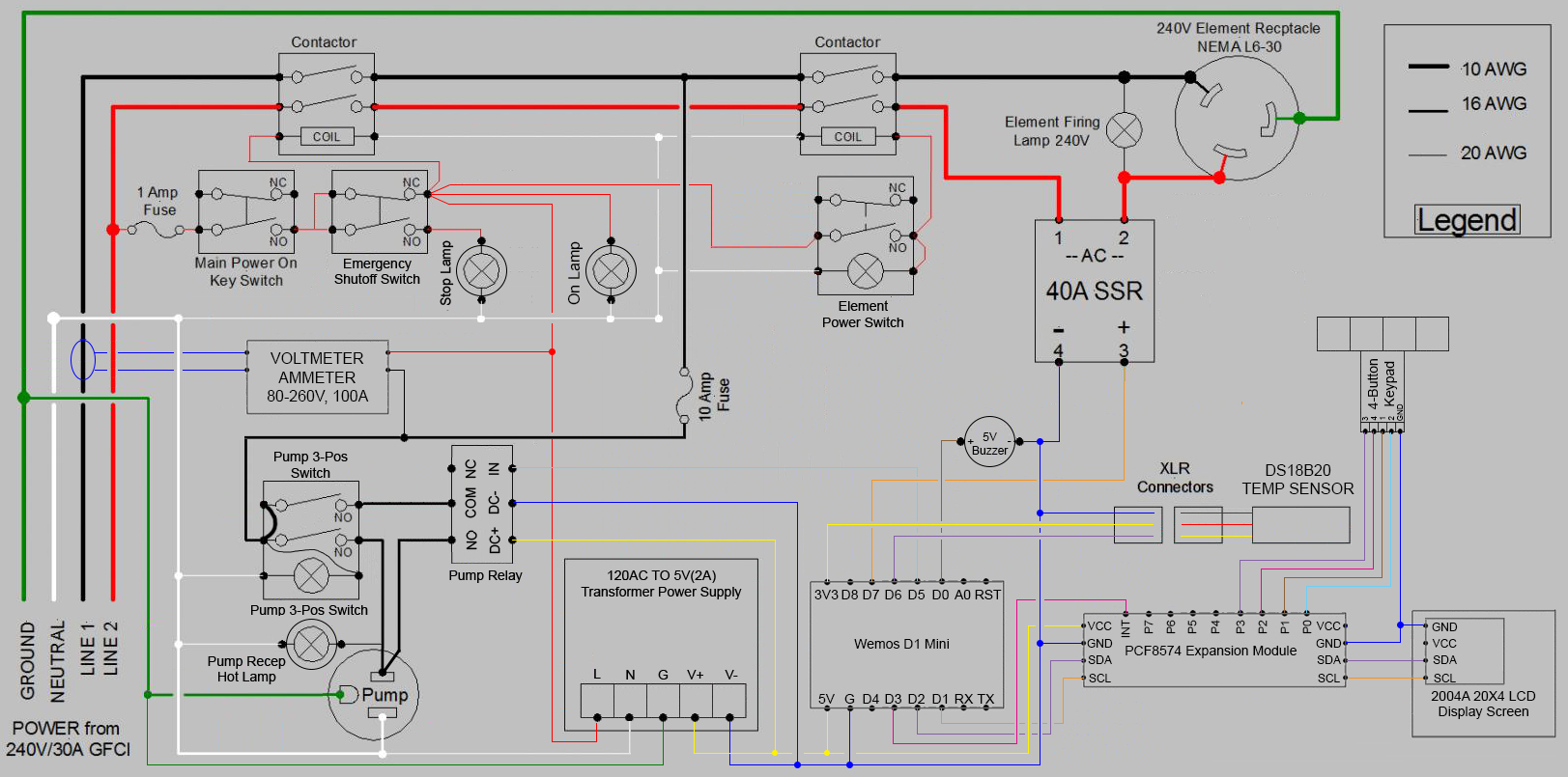
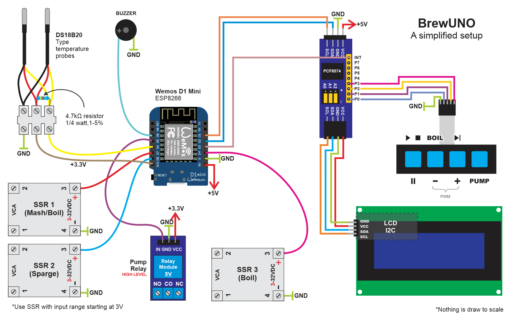
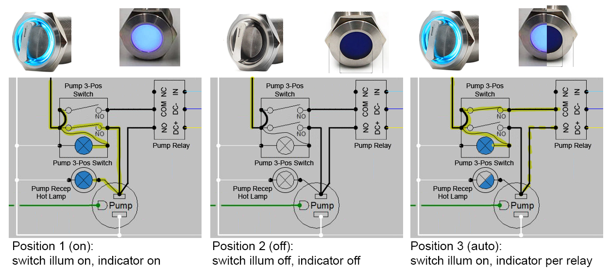
So, I have been slowly planning a eBIAB control panel. the brains of the controller will be BrewUNO and include a single 5500W element and 120V/10W MP15-RM pump (for now). I've got my 240V GFCI hot tub panel built and most of the components for the controller purchased. I think I'm ready to start cutting holes in the enclosure and wiring. Would anyone mind reviewing my wiring schematic, particularly on the AC side of things before I start making holes in the enclosure? I know it's kind of messy...I've never diagrammed anything like this before, but hope it makes sense and, most importantly, works! Thanks!!
 

Attachments

  • BrewUNO eBIAB Controller.pdf
    147.7 KB
Multiple mistakes. I'll write up the details later.

Brew on :mug:
Doug- I gave this another shot and tried to base it on one of your other designs. Does it look like I'm getting closer? Thanks again!
 

Attachments

  • BIAB-BrewUnoDiagram.jpg
    BIAB-BrewUnoDiagram.jpg
    528 KB
Sorry I forgot to get back to you. Doesn't the LCD display need 5V connected to Vcc? Other than that the modified design should work - I don't see anything functionally wrong (although I can't say anything about the I/Os from your microcontroller.

Curious why you want to have a lamp in your 3-way (Manual/Off/Auto) pump switch. The way you have it wired it will always be on whenever the main power is on.

Also, have you really analyzed the need for an emergency power off switch? You already have one switch that will cut all power to the system located in essentially the same place.

Brew on :mug:
 
Yes the display does need power, right out of the adjacent expansion module pass-through. Guess I forgot that line...woops. Also forgot the resistor for the temp sensor on the latest diagram. I have all the DC controller stuff up and running using a different 5v power supply, so I just need to hook it up the the AC side of things.

As far as the pump switch goes, I was trying to make this work:
  • Position 1- "on" circuit closed. Switch illumination on and receptacle "hot" lamp on.
  • Position 2- circuit open in both other positions. No switch illumination (is this possible?) and receptacle "hot" lamp off.
  • Position 3- "auto" circuit is closed. Switch illumination on, receptacle "hot" lamp cycles on/off depending on controller/relay.
Is there a way to make this work? I guess there's not really a need for the emergency switch...I just thought that smashing a giant red mushroom cap is a little easier that fat fingering a little rotary switch/key in a crisis. Thanks again so much for your review and assistance!
 

Attachments

  • BrewUNO.png
    BrewUNO.png
    231.6 KB
  • pump scheme.png
    pump scheme.png
    272.2 KB
  • switch terminals.png
    switch terminals.png
    108.2 KB
The pump power on lamp will work as you intend it to.

There is no way to get the switch lamp to work the way you want (at least that I can see.) You can't tie the lamp power to the NO contacts, or you make switch positions "left" and "right" the same (which powers up the receptacle, and prevents the Uno from controlling the pump.) The way you currently have it diagrammed, the lamp will always be on when the system is powered up.

Brew on :mug:
 
That's what I figured after you drew my attention to it. I guess I'll just connect the switch illumination to the 'auto' NO contact only. When I switch to the 'on' position the hot receptacle panel lamp will turn on. That's enough indication for me to know that the receptacle is hot. Cheers!
 
Back
Top