My Honeywell valves are V800's
You are using an out of date browser. It may not display this or other websites correctly.
You should upgrade or use an alternative browser.
You should upgrade or use an alternative browser.
Automated HERMS system
- Thread starter blackheart
- Start date

Help Support Homebrew Talk:
This site may earn a commission from merchant affiliate
links, including eBay, Amazon, and others.
OP
OP
blackheart
Well-Known Member
Beerthirty, Thanks for the info. We will definitally kick down the burners a bit then. what do you think of these?
I was inspired by the brewtroller to write my own interface with similar hardware. For me, building the system is half the fun! They have a nice system but I want to integrate a little different hardware, namely the ethernet portion which isnt possible with the proprietary PCB they have made.
Cape Brewing. Your pictures were great at explaining you system, I know how long they take to make, I have done it at least 4 times now. I have a Mac but MS Paint is still the best at drawing quick pictures. We are studying your pictures as well as the ones kladue posted and hopefully we will be able to combine both concepts along with our current one and see if we cant figure out a no-change, or maybe a 1 change system.
Hi temp hose will still be used just because it will be easier to move things etc. Also considering Tri-clover fittings. Found a sweet source for them too. Really cool web site I wanted to share with you guys. brewershardware.com They also have digital temp probes that are installed in thermowells already as well as other cool things.
I have a bit of time free this week at work which I am hoping to use to finish the design, have you guys check it once more, then start ordering parts! A significant influx of cash has come our way as I finally got paid for some consulting work I did and it looks like it will be able to cover the parts costs.
Thanks again everyone for the part numbers and pictures!
Good luck. For me, building it was half the fun.
I'm hard-plumbed throughout the entire thing with everything connected with unions so if I really want to, I can break the whole thing down into small pieces. The only flexible piece is the high-temp, food safe silicone tubing that connects into the lid of my MLT.
... and everything stays right where it is for cleaning except for the MLT. I take that off to rinse out any straggler grains after shoveling it out (which takes all of a minute). Other than that, everything stays connected and I run boiling water, PBW and star san through it to clean and sanitize. I've done a whole bunch of batches on it at this point and no problems with infections or anything like that.
OP
OP
blackheart
Well-Known Member
This is one of the burners we were looking at. It seems they have really good prices. Is this one too big?
8", 20 tip, 150,000 BTUs
They also have a few other models as well.
8", 20 tip, 150,000 BTUs
They also have a few other models as well.
The jet burners use a venturi (Bernouli's law) to mix the gas and air. They can't be adjusted for heat output very well due to this. IIRC
OP
OP
blackheart
Well-Known Member
There might be a better way to do this or with less valves (10) but here is what I could come up with today for a HERMS system so that the coil is also used for cooling as a giant counter flow chiller. As a bonus P2 now does the mash recirculation which leaves P1 free to circulate the HLT water keeping the temperature even without the use of a stirrer in the HLT.
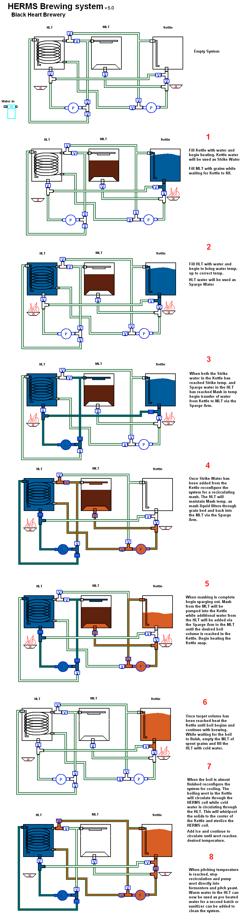
There are a few issues with this design of course. One is that it looks much more complex and the paths are a little more round about to get where things need to go. The other is that on both the MLT and Kettle inlets two separate connections need to go into each one. I'm not sure how I would do that without getting some liquid going back in the other direction but it looks like the over all idea works.
I was really hoping that I would not need like 10 valves to fully automate this. If anyone has a suggestion on some pieces I can remove that would be great. Also, I have not automated the filtered water entering the system in this picture which I am not sure how to handle without additional connections and valves.
OK Time to go home for a beer, this thinking stuff is hard!

$719.00
$799.00
EdgeStar KC2000TWIN Full Size Dual Tap Kegerator & Draft Beer Dispenser - Black
Amazon.com


![Craft A Brew - Safale BE-256 Yeast - Fermentis - Belgian Ale Dry Yeast - For Belgian & Strong Ales - Ingredients for Home Brewing - Beer Making Supplies - [3 Pack]](https://m.media-amazon.com/images/I/51bcKEwQmWL._SL500_.jpg)


$176.97
1pc Commercial Keg Manifold 2" Tri Clamp,Ball Lock Tapping Head,Pressure Gauge/Adjustable PRV for Kegging,Fermentation Control
hanhanbaihuoxiaoshoudian


$53.24
1pc Hose Barb/MFL 1.5" Tri Clamp to Ball Lock Post Liquid Gas Homebrew Kegging Fermentation Parts Brewer Hardware SUS304(Liquid Hose Barb)
yunchengshiyanhuqucuichendianzishangwuyouxiangongsi


$76.92 ($2,179.04 / Ounce)
Brewing accessories 1.5" Tri Clamp to Ball Lock Post Liquid Gas Homebrew Kegging Fermentation Parts Brewer Hardware SUS304 Brewing accessories(Gas Hose Barb)
chuhanhandianzishangwu

$20.94
$29.99
The Brew Your Own Big Book of Clone Recipes: Featuring 300 Homebrew Recipes from Your Favorite Breweries
Amazon.com

$44.99
$49.95
Craft A Brew - Mead Making Kit – Reusable Make Your Own Mead Kit – Yields 1 Gallon of Mead
Craft a Brew


$58.16
HUIZHUGS Brewing Equipment Keg Ball Lock Faucet 30cm Reinforced Silicone Hose Secondary Fermentation Homebrew Kegging Brewing Equipment
xiangshuizhenzhanglingfengshop


$10.99 ($31.16 / Ounce)
Hornindal Kveik Yeast for Homebrewing - Mead, Cider, Wine, Beer - 10g Packet - Saccharomyces Cerevisiae - Sold by Shadowhive.com
Shadowhive

$7.79 ($7.79 / Count)
Craft A Brew - LalBrew Voss™ - Kveik Ale Yeast - For Craft Lagers - Ingredients for Home Brewing - Beer Making Supplies - (1 Pack)
Craft a Brew

$28.98
Five Star - 6022b_ - Star San - 32 Ounce - High Foaming Sanitizer
Great Fermentations of Indiana


$172.35
2 Inch Tri Clamp Keg Manifold With Ball Lock Posts, Pressure Gauge, PRV (0-30 PSI) – Homebrew, Fermentation, Kegging System
wuhanshijiayangzhiyimaoyiyouxiangongsi


$33.99 ($17.00 / Count)
$41.99 ($21.00 / Count)
2 Pack 1 Gallon Large Fermentation Jars with 3 Airlocks and 2 SCREW Lids(100% Airtight Heavy Duty Lid w Silicone) - Wide Mouth Glass Jars w Scale Mark - Pickle Jars for Sauerkraut, Sourdough Starter
Qianfenie Direct


$159.99 ($26.66 / Count)
3M High Flow Series System BREW120-MS, 5616001, For Brewed Coffee and Hot Tea, Valve-in-Head Design
SpaceCityProviders


$479.00
$559.00
EdgeStar KC1000SS Craft Brew Kegerator for 1/6 Barrel and Cornelius Kegs
Amazon.com


$22.00 ($623.23 / Ounce)
AMZLMPKNTW Ball Lock Sample Faucet 30cm Reinforced Silicone Hose Secondary Fermentation Homebrew Kegging joyful
无为中南商贸有限公司

$53.24
1pc Hose Barb/MFL 1.5" Tri Clamp to Ball Lock Post Liquid Gas Homebrew Kegging Fermentation Parts Brewer Hardware SUS304(Gas Hose Barb)
Guangshui Weilu You Trading Co., Ltd
Looking good. Couple of questions. Why does the inlet in the HLT open at the bottom of the kettle? This seems counterproductive during the cooling stage, since most of the HX coil is above this point. In step 7, do you plan of recircing the boiling wort through the HX before adding the water and ice? As joe camel stated it wont sanitize the HX after the cooling water ha been added.
OP
OP
blackheart
Well-Known Member
Looking good. Couple of questions. Why does the inlet in the HLT open at the bottom of the kettle? This seems counterproductive during the cooling stage, since most of the HX coil is above this point. In step 7, do you plan of recircing the boiling wort through the HX before adding the water and ice? As joe camel stated it wont sanitize the HX after the cooling water ha been added.
The HLT inlet is on the the top left so im not sure what your referring to.
During the cooling phase the HLT will recirculate ice water through itself via P1 or possibly the HLT + another chiller. At the same time the wort in the Kettle will circulate through the HERMS coil and back into the Kettle via the inlet which will whirlpool the wort while it is cooling.
we will run the boiling wort through the herms and start the wort recirculation prior to putting any water in the HLT for cooling as suggested. Its a minor change to the specific steps listed and has been omitted from this drawing to save some space. When the wort is cooled we will connect to the fermentors and continue to pump it through the herms and out.
So if we were to go with this design... then I guess I have two questions.
1. What do we do for the MLT and Kettle inlets where 2 things need to be connected to the same inlet?
2. What type of connections are best? if we are making a system that needs virtually no hose changes then are we really going to see a benefit from QD's or tri-clover connections?
and a final question, Full automation would be ideal, but at the cost of 10 electronic valves and many more connectors and fittings vs changing hoses 2-3 times. I'm just trying to think in terms of scalability so we can use the same parts and swap out the pots at a later date, and the ease of other things like cleaning/maintenance.
Boerderij_Kabouter
Well-Known Member
Here is a possible alternative design...
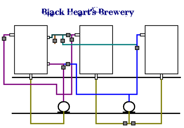
You get away with one less valve and I think you may be able to route the lines in a more attractive manner... who knows.
:EDIT: Pardon my laziness and crappy layout. I am swamped at work and just used this as a 10 minute break. Obviously the routing would be much prettier and the manifolds more practically laid out if you took the time to actually design it.
:EDIT::EDIT: It was driving me nuts. I made it a little better now.
pfft...
yeah... like you're gonna listen to a guy who sniffs donkeys...
I'm not going to get into and argument on the jet-tip burners... I've fought that fight too many times on other threads and everyone tells me I'm wrong adn what I have going in my garage is some kind of mirage or something. So I'm going go to say it just in this single post... I have two 32-tip burners. They run on NG. I run then through two Honeywell V800s and mine are adjustable. If I adjust the gas valve, I can bring my flame down to three inches or if I jack them up, I can get that flame to be 30 inches (seriously). Everyone posts "you can't adjsut those burners"... well... I don't know how I'm doin' it then. My burners DO burn dirty though. I DO get soot on my pots.
My father teaches natural gas heating at a technical college and swears the soot is only there becuase I have the burners too close to the pots and as the gas and flame hit the pot, the pot actually cools the gas enough so that it doesn't fully burn up. According to him... if I simply raised my pots a couple of inches or lowered my burners, I wouldn't have any soot at all.
Since my entire rig is hard plumbed and the burners were the last peices to go it... raising the pots or lowering the burners isn't possible unless I wanted to re-do all sorts of stuff. I probably will someday but in the mean time... my burners are controlled. I CAN adjust the flame and therefore heat output. They DO put out a AZZLOAD of heat even after adjusted way way down and mine DO burn dirty. Given the issues I had with other burners, I LOVE how much heat I get out of my 32's... and if I have to deal with a little soot and not burning my NG as efficiently as I possibly could... I'll live with it.
. We are studying your pictures as well as the ones kladue posted and hopefully we will be able to combine both concepts along with our current one and see if we cant figure out a no-change, or maybe a 1 change system.
I'm confused... the design I used is a no-change... (unless I don't know what "no change" means). You mean so that you don't have any manually change connections or anything right?
The only manually things I do are open the ball valve at the end to pour our chilled wort and connect a garden hose from my house into the other half of the plate chiller so cold water gets fed into it...
You seem kinda touchy today cape. I withdraw the laws of physics since you seem to have found away around them.
Blackheart, I was referring to the pipe that appears to go to the bottom of the inside of the HLT from the top water inlet. It appears that the water enters and exits near the bottom of the kettle. I must not be looking at it correctly.
Blackheart, I was referring to the pipe that appears to go to the bottom of the inside of the HLT from the top water inlet. It appears that the water enters and exits near the bottom of the kettle. I must not be looking at it correctly.
Uggg.. not touchy at all... it's just I've been told like 600 times that you can't control those burners and yet I seem to be able to.
I dunno... maybe we're talking about two different things... I'm not a gas guy so maybe I'm thinking about something totally different.
If I take the pots off my rig... light my burners... and turn the adjustment screw on the top of my gas valve one way... the flame will go from three inches to freakin' two and half feet of blue flame... if I turn it the other way... I can get it down to three/four inch blue flame.
Are you saying I can't do that? I'm not being all pissy, I would honestly love to settle this because as I mentioned, I've been in arguments over this a bunch of times in other threads where people tell me that's impossible.
OP
OP
blackheart
Well-Known Member
Beerthirty. I get what your saying now. I think I was thinking that adding the tub to the bottom of the HLT would create a whirlpool effect that would transfer heat. What is better, whirlpooling the HLT water or just pumping it in the top and out the bottom?
Capebrewing, We liked your design but it does not use the HERMS coil as the chilling device which is partially why we chose the HERMS design.
Boerderij, I think that the v5 that we posted would work better if we moved the valves that are next to the pump out up to the kettle and MLT inlets like you have in your design.
I think that both this v5 design and the v4 design with work, its just a question of automation vs hose changes and the cost of each. Here is a quick overview.
Full-automated v5
20 pairs of disconnects
10 valves
7 T connectors
8 bulkheads
Semi-automated v4
15 pairs of disconnects
4 valves
3 T connectors
so it looks like the cost of going fully automated is going to come down to the cost of the valves which is more than double. I found a pair of tri clover disconnects with a 1/2" male MPT thread on one side and a barb on the other for attaching to hi temp tubing. also includes the clamp to connect them together. $35 a set vs $31 for a SS QD from more beer thats not tri-clover.
20 pairs of tri-clover connectors @ $35 = $700 .... outch...
we are going to end up spending like $2000 on SS connectors and adaptors lol.
8 bulkheads
Naw buddy. I'm know it is possible. The venturi principle is used in float type carburetors to draw liquid fuel up into the throat of the carb. At different velocities the efficiency will change but fuel is still drawn up(same as in a burner, but with greater ease since the fuel is a gas not a liquid in a burner) In your burner at one point you have optimum fuel/air ratio where at others points the ratio is not optimum for efficient burn. That does not say it wont work, just that you could get more heat with the optimum mix of fuel and air. Other burners use the same principle but both air and fuel can be adjusted where the jet burner can only be adjust for fuel. I dont use the jet burner simply due to economics and was just pointing out the flaw in that design. BTW I was on vaca in PA and googled to see how far away you were hoping to get a chance to meet you and check out your rig. Alas the east coast is larger in areas than I thought it was.
Blackheart, although whirlpooling does move liquid from top to bottom and negate the need for a stirrer. I think better water movement would occur if it was force pumped top to bottom.
Yeah... you're looking at a solid five hours, minimum, from PA up to my neck a' the woods.
OP
OP
blackheart
Well-Known Member
OK so here is version 6!
Here are some assumptions...
- Space in plumbing where liquid COULD go but eventually doesnt because a valve is in the way is negligible and does not hurt anything.
- The HLT does not need a valve as it is the only thing going IN to the pump so if the pump is OFF then the HLT water will go nowhere....
- No hose changes except at the end to connect to fermentor, no point in automating this as the connector going from the HERMS coil out into the Kettle in is already sanitary and long enough and additional things like a O2 stone and inline temp probe may be added.
* I also added the HERMS coil sanitizing step to this picture..... This is *hopefully* the final design and we can start counting parts from this design and order stuff as soon as tomorrow!!!
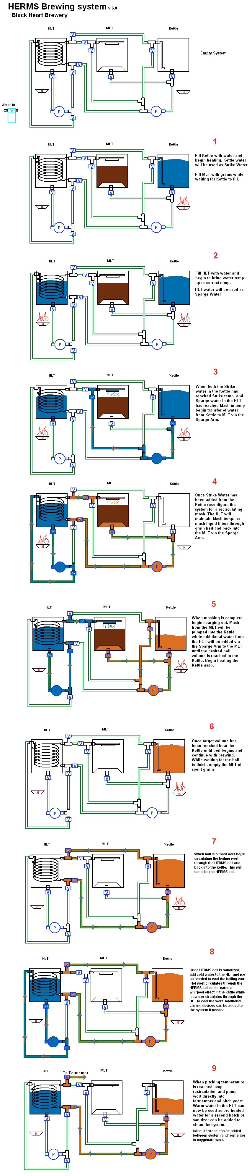
Thoughts?
Here are some assumptions...
- Space in plumbing where liquid COULD go but eventually doesnt because a valve is in the way is negligible and does not hurt anything.
- The HLT does not need a valve as it is the only thing going IN to the pump so if the pump is OFF then the HLT water will go nowhere....
- No hose changes except at the end to connect to fermentor, no point in automating this as the connector going from the HERMS coil out into the Kettle in is already sanitary and long enough and additional things like a O2 stone and inline temp probe may be added.
* I also added the HERMS coil sanitizing step to this picture..... This is *hopefully* the final design and we can start counting parts from this design and order stuff as soon as tomorrow!!!
Thoughts?
Boerderij_Kabouter
Well-Known Member
Looks sexy to me. The only thing I see is you could cut out is the valve you use in step 3. You could fill the MLT with strike water by pumping through the coil. That would allow you to save some dough on one valve, a tee and some tubing.
It definitely isn't bad to have that extra run in there just a little redundant. I think that looks great now!
Well thought out! You and your pocket book will be happy you took the time to plan it out.
Cheers!!!
It definitely isn't bad to have that extra run in there just a little redundant. I think that looks great now!
Well thought out! You and your pocket book will be happy you took the time to plan it out.
Cheers!!!
OP
OP
blackheart
Well-Known Member
I thought about doing that too... The only issue is the strike water would be hotter than the mashing/sparge water and by passing through the coil would give unpredictable results. We would have to then heat both to strike temperature which would take longer and just waist energy heating water in the HLT that will just need to cool anyway.
Thanks for your input and drawing earlier Boerderij, I think this is about as effecent as we can get at this point. I am happy with the design, and unless I hear otherwise from somone else by tomorrow we are going to go ahead and start ordering stuff we know we need like tri-clover connectors and other pieces.
Thanks for your input and drawing earlier Boerderij, I think this is about as effecent as we can get at this point. I am happy with the design, and unless I hear otherwise from somone else by tomorrow we are going to go ahead and start ordering stuff we know we need like tri-clover connectors and other pieces.
Looks great. I had a couple of thoughts... none major but just some things you might want to think about.
- (more of a general question just 'cause I'm curious)... how are you filling your HLT and BK?
- in step 3, I think you're going to lose a ton of heat dumping your strike water into the MLT through a sparge arm. It's not necessarily a bad thing... just something you'll have to compensate for. If you calculate (or have Beersmith or something calculate) that you need 9 gallons of 164 degree strike water for a given mash temp once you add your grains... you're going to have to pump something like 169-170 degree water from the BK into the MLT to compensate for the lost temp in transfer. Again, not a problem... but something you should test out a couple of times before your first batch.
- in step 4... are you circulating your HLT as well?? Just my opinion but I don't think you'll need to do that at all. I hear you that you want a consistant temp in the HLT but I think that's overkill.
- in step 8... once you go through all of those connections and the heat exchanger coil in the HLT, I think you're going to lose too much pressure to really have an effective whirlpool.... I go very directly from the BK to my plate chiller and back and I had to purposely circumvent my chiller as I was losing too much pressure. I would think you'll have the same issue with that much distance from start to finish. Maybe not though... just trying to cover any and all bases before you build.
Boerderij_Kabouter
Well-Known Member
- in step 3, I think you're going to lose a ton of heat dumping your strike water into the MLT through a sparge arm.
Just a question, but why are you using a sparge arm? I think many of us have found them to be more trouble than they are worth. I just use a section of tubing that sits on top of the grain and creates a mini whirlpool on top of the grain bed to evenly distribute the liquor. This way you have no chance of clogging and it is easy to adjust. The idea came from Sabco, it is how the brew magic works.
Add the additional valve to the hlt. The pump will not suffice as a valve when in the off position. Unless the pump is vapor locked which is what causes the priming issues with these pumps, liquid will flow through it.
OP
OP
blackheart
Well-Known Member
OK lots to cover here so lets get started.....
First, answer some questions.
The sparge arm was really a loose term in the plans here. We havent decided how we would get liquid onto the top of the grain bed the best way. As many people have suggested, this will most likely be the Sabaco method of a coiled tube, the same 1/2" ID hi-temp tubing we are using for everything else. This should take care of any flow restrictions etc. and temp concerns as well.
Yes I have included that the HLT is recirculating any time the pump is free. Is this overkill, maybe, is an automated brewing system overkill? This is one of the many things that we have the option to do or not do, I thought it was a cool idea so I am including it in the plans for now but there can just as easily be a software switch to enable/disable.
Same goes for the whirlpooling. Pump 2 can be setup to pump wort from the Kettle out to the Kettle in just by turning on the right valves. In this case we could sanatize both the short path back into the kettle and the long path through the coil before chilling, then once chilled to the right temp for pitching we could switch back to the short path and whirlpool and then open one of many connections to get the cooled wort out.
Thats what I really like about this system, if we use standard Tri-clover clamps on everything then any part can connect to another or we can easily add new parts or reconfigure the whole system. I really think this is the most efficient system for all of the different things we are trying to do with the equipment.
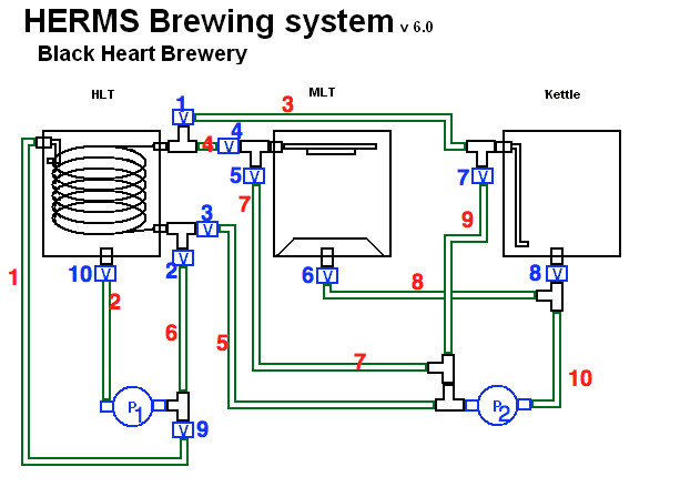
So here is the new stuff! First, I changed the v6 picture on the previous page to reflect the addition of a 10th valve on the HLT as I thought we might need. I took some time to draw everything out in paint instead of doing a photoshopped layout which can be less clear and take more time.
Here are some of the parts you will be seeing.
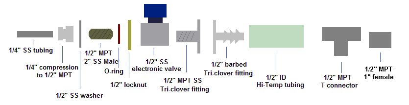
Here is a reference of the overall system layout. The red numbers are the connections and the blue numbers are the valve numbers.
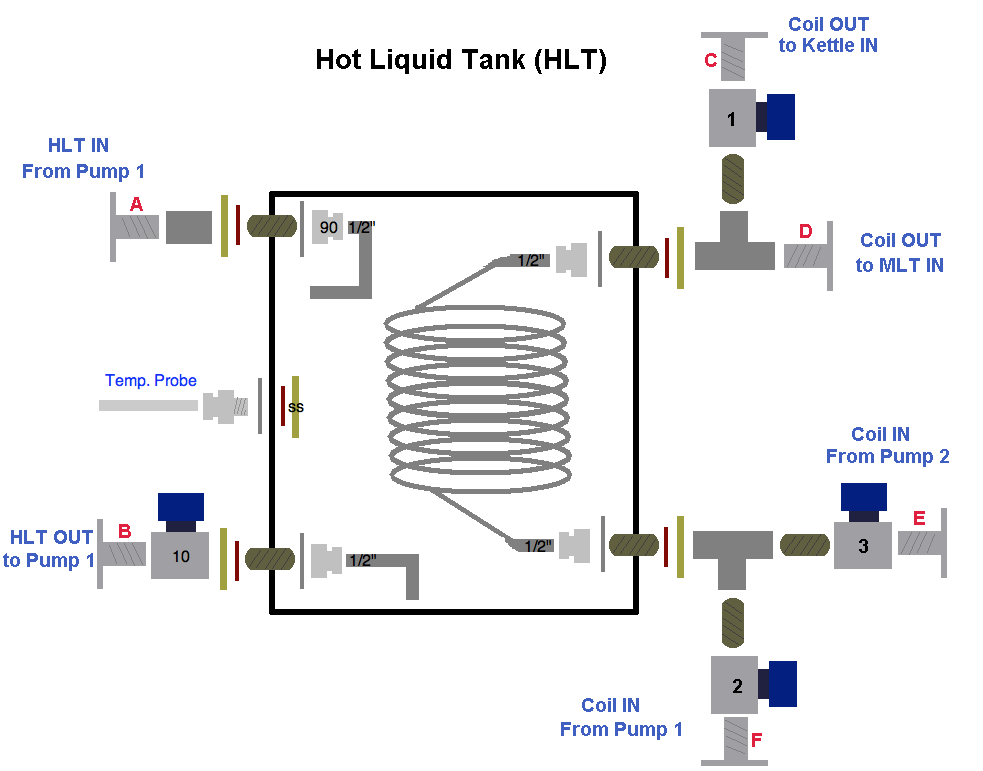
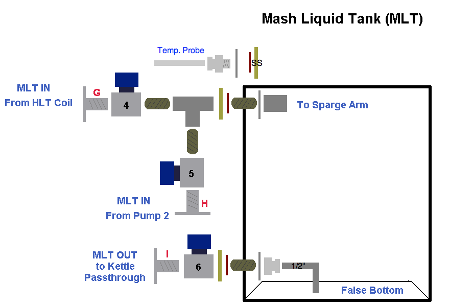
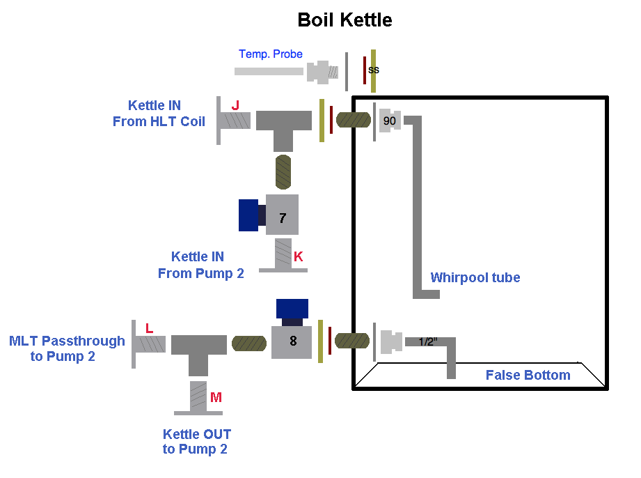
And on to the vessels. Red letters are to mark connections between vessels and pumps etc. Numbers on valves correspond to the numbers on the overview above.
HLT
MLT
Kettle
Pumps
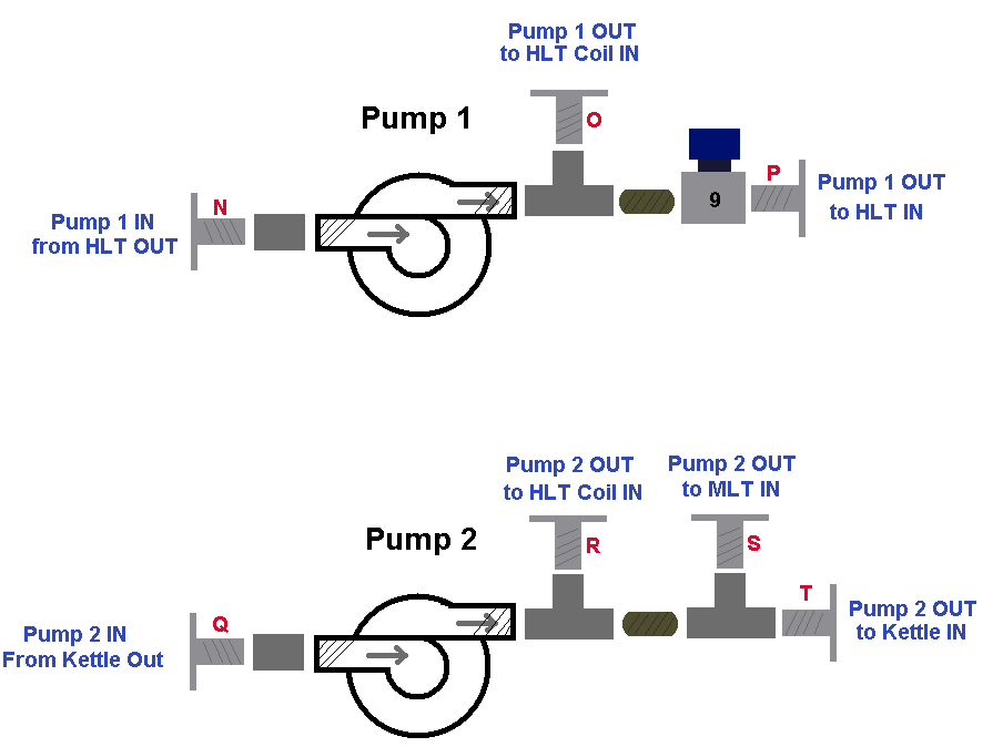
Connections
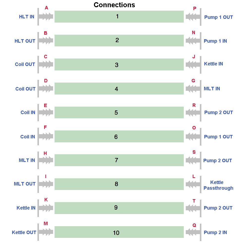
So that should cover the entire overview of the parts and the detail of each system down to the last O-Ring and washer. There is a good chance that something is mislabeled or I am missing/forgetting something. This is of course only the Liquid side of things, there is a gas component, which is more strait forward and most of the parts I can buy locally, though I will take some time to draw this up as well.
What do you think?
Any suggestions on SS tubing diameter for the coil, dip tubes, whirlpool return?
What do I use to clamp the tubing to the barbed Tri-clover fittings? a worm gear clamp or something else?
Do we use teflon tape on all threaded connections inside and out? will this effect anything?
First, answer some questions.
The sparge arm was really a loose term in the plans here. We havent decided how we would get liquid onto the top of the grain bed the best way. As many people have suggested, this will most likely be the Sabaco method of a coiled tube, the same 1/2" ID hi-temp tubing we are using for everything else. This should take care of any flow restrictions etc. and temp concerns as well.
Yes I have included that the HLT is recirculating any time the pump is free. Is this overkill, maybe, is an automated brewing system overkill? This is one of the many things that we have the option to do or not do, I thought it was a cool idea so I am including it in the plans for now but there can just as easily be a software switch to enable/disable.
Same goes for the whirlpooling. Pump 2 can be setup to pump wort from the Kettle out to the Kettle in just by turning on the right valves. In this case we could sanatize both the short path back into the kettle and the long path through the coil before chilling, then once chilled to the right temp for pitching we could switch back to the short path and whirlpool and then open one of many connections to get the cooled wort out.
Thats what I really like about this system, if we use standard Tri-clover clamps on everything then any part can connect to another or we can easily add new parts or reconfigure the whole system. I really think this is the most efficient system for all of the different things we are trying to do with the equipment.
So here is the new stuff! First, I changed the v6 picture on the previous page to reflect the addition of a 10th valve on the HLT as I thought we might need. I took some time to draw everything out in paint instead of doing a photoshopped layout which can be less clear and take more time.
Here are some of the parts you will be seeing.
Here is a reference of the overall system layout. The red numbers are the connections and the blue numbers are the valve numbers.
And on to the vessels. Red letters are to mark connections between vessels and pumps etc. Numbers on valves correspond to the numbers on the overview above.
HLT
MLT
Kettle
Pumps
Connections
So that should cover the entire overview of the parts and the detail of each system down to the last O-Ring and washer. There is a good chance that something is mislabeled or I am missing/forgetting something. This is of course only the Liquid side of things, there is a gas component, which is more strait forward and most of the parts I can buy locally, though I will take some time to draw this up as well.
What do you think?
Any suggestions on SS tubing diameter for the coil, dip tubes, whirlpool return?
What do I use to clamp the tubing to the barbed Tri-clover fittings? a worm gear clamp or something else?
Do we use teflon tape on all threaded connections inside and out? will this effect anything?
Boerderij_Kabouter
Well-Known Member
Looks awesome!
I would suggest going absolutely no lower than 1/2" on the tubing. You flow will be severely limited if you go with 3/8, especially on the low pressure side of the pump.
I would suggest going absolutely no lower than 1/2" on the tubing. You flow will be severely limited if you go with 3/8, especially on the low pressure side of the pump.
OP
OP
blackheart
Well-Known Member
Looks awesome!
I would suggest going absolutely no lower than 1/2" on the tubing. You flow will be severely limited if you go with 3/8, especially on the low pressure side of the pump.
Thanks! Went with 1/2" for everything because it was easiest. Pump is 1/2", tubing is readily available in 1/2", clover fittings are 1/2" etc etc so I hope those are all ok. I dont know what the largest tubing you can fit inside a 1/2" MPT to compression fitting is but I am guessing that 3/8 is pretty close....
*edit* it looks like you have a sketchup model of a 1/2" MPT to 1/2" compression fitting... so I am guessing we could go with 1/2" SS tubing for everything. Is that a good/bad idea?
Boerderij_Kabouter
Well-Known Member
That is a good idea.
You can get MPT x compression in almost any combination (e.g, 3/8 MPt x 1" compression, 2" mpt x 1/4" compression, etc.). 1/2"MPT x 1/2" compression with 1/2" stainless tubing makes the most sense for us IMO.
McMaster has been the cheapest source of SS tube I have been able to find. Let me know if you can find it cheaper.
OP
OP
blackheart
Well-Known Member
That is a good idea.
You can get MPT x compression in almost any combination (e.g, 3/8 MPt x 1" compression, 2" mpt x 1/4" compression, etc.). 1/2"MPT x 1/2" compression with 1/2" stainless tubing makes the most sense for us IMO.
McMaster has been the cheapest source of SS tube I have been able to find. Let me know if you can find it cheaper.
I started looking online... then I realized I know nothing about the exact specs of SS tubing we need. what ID/OD, thickness, etc is needed to work with the compression fittings? (which are different from flared fittings???)
Boerderij_Kabouter
Well-Known Member
For your swagelok fittings I STRONGLY suggest getting them on Ebay. You WILL save between 50-80% off retail for brand new fittings.
Find your swagelok fitting numbers from swagelok's site, then search that number on Ebay.
example:
SS-810-8-8, great deals on on eBay!
You can find better deals by searching "swagelok" and sifting through the broad listings, but it takes more time.
McMaster # 8989K95 - Stainless 304 1/2" OD tubing in 6' lengths for $12.61 a piece.
Not sure where you plan to get your valves but I have found DudaDiesel.com Biodiesel Supplies. They have mostly 2-way stuff in the sizes that you're looking for but the prices seem pretty good. Plus they all use Viton seals so they're good up to ~250 F.
Similar threads
- Replies
- 0
- Views
- 377
- Replies
- 0
- Views
- 345
- Replies
- 5
- Views
- 713
