• Please visit and share your knowledge at our sister communities:
  • If you have not, please join our official Homebrewing Facebook Group!

    Homebrewing Facebook Group

Automated HERMS system

Homebrew Talk

Help Support Homebrew Talk:

This site may earn a commission from merchant affiliate links, including eBay, Amazon, and others.
In your newest iteration I have a concern. In step 7 you recirculate the boiling wort to sanitize the herms coil for cooling. It won't sanitize if the HLT is full of cold water at the time, it'll cool the wort below sanitizing temps. Best to circulate with the HLT empty first, then add the ice and water at flame out.

Otherwise, your rig is getting slicker and slicker.

Cheers
 
You might want to look at BeerThirty's rig, 3 keggles, 6 solenoid valves in wort/water paths and 2 pumps, with no plumbing changes needed during brewing. Add in pressure sensors for level control electric burner ignition, and solenoid valves for fill water, cooling water control to plate chiller for a complete mobile system controlled by the Brewtroller.

... that's how I did mine... only I have nine solenoids because I wasn'y smart enough to make it efficient enough to just use six.

That's what I was asking before on how automated this was going to be... "just flip buttons" vs "brew while you're not there"

I can sit on a chair and other than dumping in grain, stirring once or twice and adding hops... all I do is flip switches.
 
I posted on beer thirty's thread about his new system but its short on details. we would like to make it as automated as possible, with the exception being to add grains and hops.

How did/would you connect your system to be automated Cape Brewing?
 
I posted on beer thirty's thread about his new system but its short on details. we would like to make it as automated as possible, with the exception being to add grains and hops.

How did/would you connect your system to be automated Cape Brewing?

I would simply need a computer to run all of the switches, put in some sort of flowmeters for volume control and then build something to do my hop additions. Everything else is done.

A motorized mash rake would also be a good-to-have. I have the motor but never bothered to build a rake or hook it up

I quick connect a hose to one end that runs through a water filter and then it hits the first solenoid.
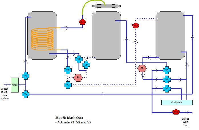
- fill HLT - a switch
- fill BK - a switch
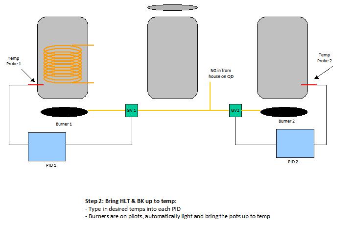
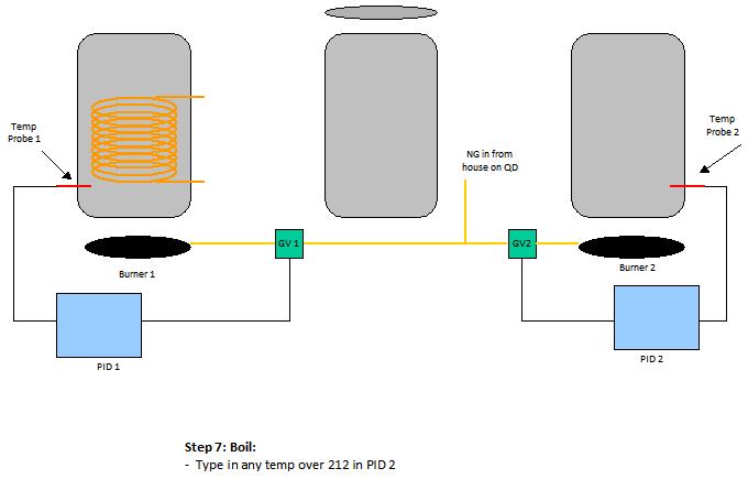
- bring HLT up to temp - type in temp on PID
- bring BK up to temp - type in temp on PID
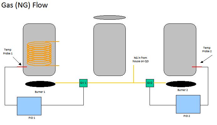
(I have two 32 tip jet burners on pilot and they run off the PIDs)
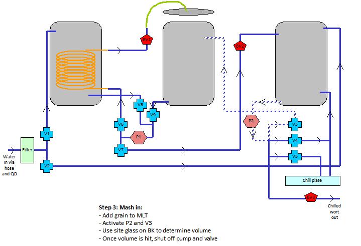
- fill MLT from BK - a switch
- add grain (or simply have grain already in there)
(motorized rake would be needed if going fully automated)
- circulate MLT through heat-ex in HLT - a switch
- mash out - a switch
- sparge - a switch
- boil - jack PID up over 212 degrees
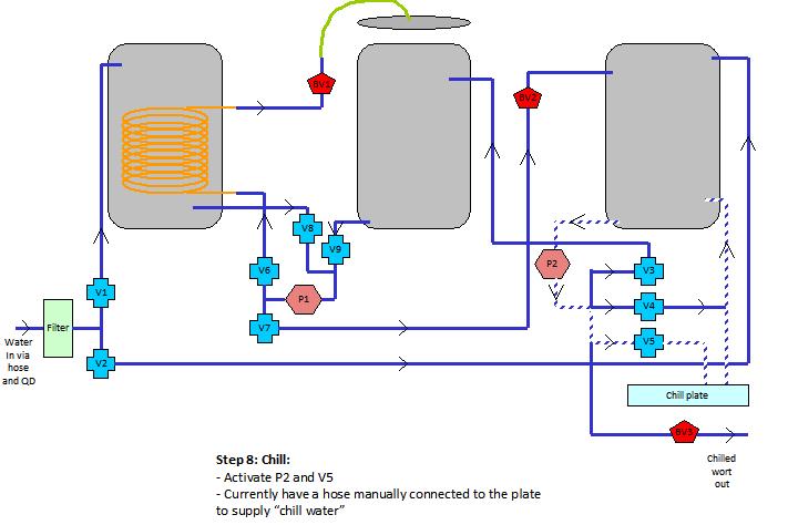
- Chill - a switch (although I would have to have one more solenoid that ran water to the chill plate... right now I hook up a hose manually... so I guess I lied... it's not ALL flip a switch).
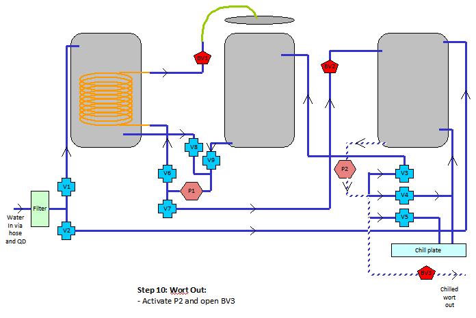
- pump into fementer - a switch.

so I plug a hose into one end... flip a bunch of switches... and cooled wort comes out the other end.

Or are you looking for a schematic?
 
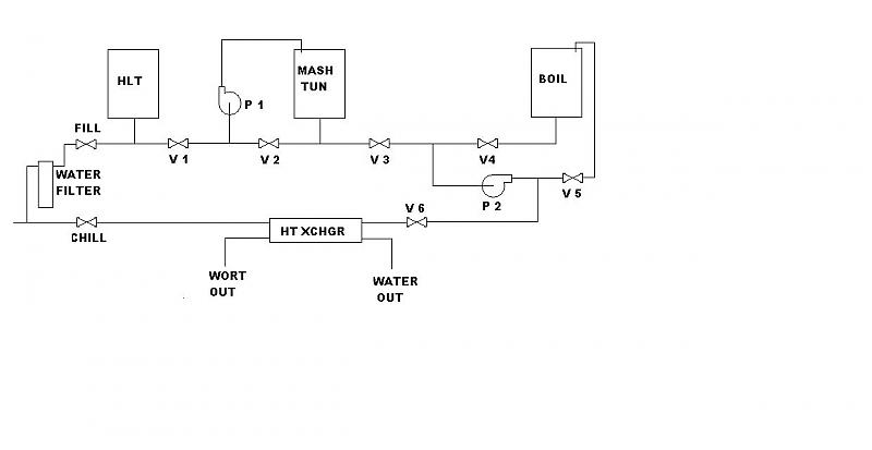
Here is a quick and dirty schematic of the liquid side of "BeerThirty's" rig

Beerthirty.jpg
 
a schematic of how you connected everything together so there are no (or just one) hose change and the rest is flipping switches would be amazing. Basically we are going to construct it as a manual flip the switch to do something then get the micro to control the switch flipping and incorporate the PID controls.

Also, any info you have on electronic valves would be great. Valves for the gas and liquid both. Does your PID do a good job of ramping up to and hitting the right temps?

Thanks for the picture kladue. I am assuming that the system is not HERMS and that the connections are simplified in that picture, so I dont know if it would work but the idea that there could be semi permeant plumbing and no hose changes appeals greatly to us.
 
My rig is direct fire RIMS, but it would not take much to reroute a few feet of tubing to make it a herms with the addition of a HE coil in the HLT. The plumbing can indeed be permanent without hose changes, mine is. We just added some teflon tubing to allow the tuns to be tipped for cleaning without disconnecting any plumbing. Once the control box is finished the only thing I will have to do is add hops(auto carousel to come in the future) and move the chilled wort hose from recircing the BK to fill the fermenters.
 
a schematic of how you connected everything together so there are no (or just one) hose change and the rest is flipping switches would be amazing. Basically we are going to construct it as a manual flip the switch to do something then get the micro to control the switch flipping and incorporate the PID controls.

Also, any info you have on electronic valves would be great. Valves for the gas and liquid both. Does your PID do a good job of ramping up to and hitting the right temps?

Thanks for the picture kladue. I am assuming that the system is not HERMS and that the connections are simplified in that picture, so I dont know if it would work but the idea that there could be semi permeant plumbing and no hose changes appeals greatly to us.


Gotcha.. (I was praying you weren't gonna say that).... I made it all up as I went along so I don't have a skematic but.. yeah, I'll sketch somethin' up. I can get you the link for the liquid solenoids as well. I have two Honeywell gas valves that hook into my PIDs for gas flow. I can get you the part #'s if you want.

I'm all hard-plumbed with no hose changes.
 
BeerThirty's rig uses teflon tubing for all the flexible connection requirements and does not need any plumbing changes during operation. If you want to do HERMS/RIMS just connect it to the pump circuit to the mash tun. For step mashing do the direct fire routine to get necessary heat input for quick step and let HERMS maintain temperature by cycling pump.
As to liquid system valving, which method of control do you want, 2 position or proportional control, Belimo for proportional, STC solenoid for 2 position. For the gas control valves, what pressure and type of burners do plan on using. If you stay under 1/2 PSI (Low pressure propane-NG) then low voltage furnace valves will work, if greater than 1/2 PSI then you again need solenoid valves.
As to the operation of BeerThirty's rig you have to ask him that as I only assisted in the construction, he is using a BrewTroller to operate everything which seems to be a good match for that type of system.
 
kladue - Thanks for the updated picture. I think I am understanding it correctly. Each one of those arrows -> is a connector and -><- is two things being connected together. In that case it appears like the input side of things is very similar to what we have drawn up for our system. The HLT and MLT go into P1 and the MLT and Kettle go into P2. It looks like if you replace the Heat exchanger for the HERMS coil its nearly identical.

What I dont understand is P1 would have to go through the heat exchanger and then to the MLT but also the P2 would need to go through the HERMS coil for cooling. And if using the Kettle to heat the strike water it would also need to be connected to the MLT in as well. I assume using the system you have to heat the HLT for strike water then heat again for sparging water?

We have a NG line running into the brewery. I am not sure what the pressure is on it but its running in from the house on a 1" line.We are planning on using the 200k+ BTU 32 tip type burners. I would imagine we need solenoid valves. How is gas flow controlled with valves? On/off/on/off PWM style or can you open the valve varying degrees?

Cape Brewing - we would love any links or part numbers you have for your valves.
 
The symbols in the drawing are solenoid valves labeled "V1-V6 and Fill-Chill, there is no need for plumbing disconnects as plumbing stays connected all the time. The HLT is filled with strike water, and when at temp it is transfered by P-1, then it is refilled with sparge water and reheated. If you want to do RIMS or HERMS just install heater after P-1. When sparging pump P-1 moves sparge water into MLT and pump P-2 moves wort to boil kettle. Save your self some extra work and go for the hurricane burners jetted for natural gas, the 32 tip burners are way to big to use as is. With NG/low pressure LP you can use 24V furnace valves for burner control with standing pilot and thermocouple for flame safety. The adjustable flow valves are quite expensive and usually not needed in this application, and require additional hardware and control signals to work.
Have you determined what control hardware you are going to use to control your system, and how you are going to interface it.

I have a few questions based on your description.

1. When you heat both the strike and sparge water in the HLT is there a significant lag time between the two? If we wanted to do HERMS and regulate temp then how long would we have to wait until we can start changing the temp from the time the strike water is added?

2. You have the plumbing listed as basically tubes coming out of the kettles and down into the valve system. Does the liquid that sits down in those tubes next to the valves effect anything or is the distance not that far as it looks?

3. Why a hurricane vs the jet burners? We are hoping to upgrade in the future to larger kettles from the kegs. How would a burner be too big?

4. Where can we find the 24v furnace valve? Also, we would now need to create a 24v power source which sounds a bit harder than 12v.

5. The control hardware is going to be a Arduino MEGA or Sanguino micro controller. We have one of each for testing. The mega has an add on ethernet shield and can act as a web server. a basic 4 button interface and 4x20 LCD will be used to display info on the system but all real control and feedback will happen via a web interface or iPhone program. Thats the plan anyway. Currently working on a proof of concept now that can control LED's and display temps.
 
sweet Jesus... it was almost as much work sketching this all out than it was building hte damn thing.

+1 on the 32 tips being too big. I have two 32 tips and I have them on 25 gallon pots... and they're too big. I have then choked WAY WAY down. I had all sorts of burner problems before these so I love my 32's... but they're way too much unless you're going to boil something really off the charts... like 100+ gallons. For anything like 25 gallons or less, the 10-tips should be more than enough. If you're looking at 25 gallons and up.. maybe the 23 tips but the 32's are insane.

I'll get you the part #s off of my gas valves, but that's what I have... 24v furnace valves off of a transformer like Kladue was saying.
 
blackheart,
1) It takes about 20-30 minutes to heat to sparge temp, and would take considerably less to heat to step temps. you could recirc without passing through the heat exchanger untill the hlt returned to temp with little to no heat loss in that time.
2) the volume that the 1/2 pipe holds is probably less than the dead space in the bottom of your kettles. Temp wise its not a problem since its recircing most of the time and wont cool down much.
3) I have 170,000 BTU burners and have only turned them up all the way once. The fuel usage far outstripped the gain in time, and made the rig dangerously hot to the point of warping rails. The extra 10 minutes is no biggie.
4) I got my furnace controls off ebay- Honeywell 8610U. one needed for each burner.
24 volt transformer- ebay. 100VA if I remember correctly.
3 position switches(installed for emergency manual control)- ebay but picked up local
5) your control hardware sounds very similar to the Brewtroller. You might want to check it out. It is inexpensive and has already undergone fairly extensive beta testing. Up to 32 controllable outputs, fermentation control and data logging. Remote access for control is the current addition they are working on. BrewTroller | BrewTroller
 
I will try to answer the questions in order:
1, The hlt is emptied and refilled after strike and it will take a bit to heat back up, not a problem with single step as the heat loss will require heat about same time water is hot again.
2, the tubing does not hold much liquid so trapped volume is not too big an issue
3, As to the burners, hurricane burners under HLT and boil kettle, 6" cast burner under MLT. The cast burners offer large turn down over small turn down range with jet burners, more is not better in this case. To big a burner and all you do is burn up the stand and send flames up the side of the keg without doing much heating.
4, look on Ebay or go to HVAC supplier for the valves, Honeywell VR 8200A for standing pilot, Honeywell VR 8345M for electric ignition applications. For pilots use the Honeywell Q314A model for standing pilot, Honeywell Q345a for electric ignition. For Valve power 24VAC -40Va transformer for one valve, 24VAC 100 VA for 3 valves as not all 3 will be in operation at same time.
If you need additional help with the gas hardware PM me and I will help you find the part numbers and sources for the parts. Look at the other Brutus builds for direction in construction so you can avoid problems with your build.
 
UGGGG.. that was like freakin' givin' birth.

I have three ball valves that are operated manually but BV1 and BV2 are simply flow controls in order to avoid stuck mashes. In an "totally automated" environment, they could be opened to a given flow rate and then just left open. And then the last ball valve is to simply pour your chilled wort out into a fermenter.

I'll grab those part numbers off the valves a bit later
 
Back
Top