how are you connecting the sensors to the beer line? I assume 1/2" NPT to 1/4" barb. Do you have any problems with foaming with that?
You are using an out of date browser. It may not display this or other websites correctly.
You should upgrade or use an alternative browser.
You should upgrade or use an alternative browser.
Arduino Based Keezer
- Thread starter citywok
- Start date

Help Support Homebrew Talk:
This site may earn a commission from merchant affiliate
links, including eBay, Amazon, and others.
how are you connecting the sensors to the beer line? I assume 1/2" NPT to 1/4" barb. Do you have any problems with foaming with that?
Yep, the beer lines are already assembled but I haven't run beer through it yet because my freezer isn't ready, but from what I've read there aren't any foaming issues with it. Tonight I should be able to close it up and start running all of the wiring, but it's going to take a while to run all of the sensors, so I may not finish it tonight. I should be just a couple days from filling my co2 tank and getting kegs.
I've used the same flow meters in a recent project to measure my sparge rates and volumes:
If you don't mind me spewing advice, here's what I found:
-- Orient the flow sensors in the exact orientation you will use them in before calibrating. They show a large sensitivity to being rotated on any axis so make sure they're firmly mounted so they won't go out of calibration because they're flopping around.
-- They are off by quite a bit as you reach the low end of their spec'ed flow range. This probably won't be a problem because you're calibrating at more or less the exact flow rate you'll be measuring.
-- The LadyAda example code is a little rough as I recall. At a serving rate of 6 pints per minute you're only getting 24 pulses per second and if you're sampling every second you might get 23 or 25 pulses per second which can add 10% error just in the sampling. I went with using TIMER1 and adding up the timer ticks and interrupt count, then dividing by the count to get a 1/62000th of a second resolution. Again, this may not be an issue because flow rate doesn't matter as much as pulse count does.
I'd like to see where this goes though, I hope you don't mind if I steal some ideas for my keezerstat as well. Mine already has an ATmega in it running the power relay, and draws a little graph, and changes colors, but I don't have any sort of volume measurement. I'd really like to see a CO2 level measurement interface so I won't run out in the middle of a party!
emperorcow
Member
- Joined
- Jan 7, 2009
- Messages
- 7
- Reaction score
- 0
The LadyAda example code is a little rough as I recall. At a serving rate of 6 pints per minute you're only getting 24 pulses per second and if you're sampling every second you might get 23 or 25 pulses per second which can add 10% error just in the sampling. I went with using TIMER1 and adding up the timer ticks and interrupt count, then dividing by the count to get a 1/62000th of a second resolution. Again, this may not be an issue because flow rate doesn't matter as much as pulse count does.
Can you share your code? I've gotten inspired and I'm going to probably start to wade into the next version of my kegerator this weekend!
If you don't mind me spewing advice, here's what I found:
-- Orient the flow sensors in the exact orientation you will use them in before calibrating. They show a large sensitivity to being rotated on any axis so make sure they're firmly mounted so they won't go out of calibration because they're flopping around.
That's great advice... I just put them on short dongles straight off the keg so I'll figure out a way to make sure they stay in the same position. Good to know!
-- They are off by quite a bit as you reach the low end of their spec'ed flow range. This probably won't be a problem because you're calibrating at more or less the exact flow rate you'll be measuring.
-- The LadyAda example code is a little rough as I recall. At a serving rate of 6 pints per minute you're only getting 24 pulses per second and if you're sampling every second you might get 23 or 25 pulses per second which can add 10% error just in the sampling. I went with using TIMER1 and adding up the timer ticks and interrupt count, then dividing by the count to get a 1/62000th of a second resolution. Again, this may not be an issue because flow rate doesn't matter as much as pulse count does.
You are exactly right, all I need for what I'm doing is total pulse count so I took their example and removed all of the flow rate stuff and added a simple counter.
I'd like to see where this goes though, I hope you don't mind if I steal some ideas for my keezerstat as well. Mine already has an ATmega in it running the power relay, and draws a little graph, and changes colors, but I don't have any sort of volume measurement. I'd really like to see a CO2 level measurement interface so I won't run out in the middle of a party!
I can't find any high pressure sensors so I'm not sure how you would measure the level other than maybe by weight of the co2 tank? This would be interesting.
Edit: How have different densities affected the accuracy? It sounds like from one beer to the next the calibration may not be the same.
Sure, emperorcow, the code to my flow meter is in github Capnbry/flowknow.
citywok, I was thinking the cheapest way to measure CO2 levels was simply measuring the weight using some of those fancy force strips. Not sure if they'd drift over time like a regular strain gauge would though.
EDIT: these Flexiforce pressure sensors
citywok, I was thinking the cheapest way to measure CO2 levels was simply measuring the weight using some of those fancy force strips. Not sure if they'd drift over time like a regular strain gauge would though.
EDIT: these Flexiforce pressure sensors

$44.99
$49.95
Craft A Brew - Mead Making Kit – Reusable Make Your Own Mead Kit – Yields 1 Gallon of Mead
Craft a Brew


$76.92 ($2,179.04 / Ounce)
Brewing accessories 1.5" Tri Clamp to Ball Lock Post Liquid Gas Homebrew Kegging Fermentation Parts Brewer Hardware SUS304 Brewing accessories(Gas Hose Barb)
chuhanhandianzishangwu


$479.00
$559.00
EdgeStar KC1000SS Craft Brew Kegerator for 1/6 Barrel and Cornelius Kegs
Amazon.com


$719.00
$799.00
EdgeStar KC2000TWIN Full Size Dual Tap Kegerator & Draft Beer Dispenser - Black
Amazon.com


$53.24
1pc Hose Barb/MFL 1.5" Tri Clamp to Ball Lock Post Liquid Gas Homebrew Kegging Fermentation Parts Brewer Hardware SUS304(Gas MFL)
Guangshui Weilu You Trading Co., Ltd


![Craft A Brew - Safale S-04 Dry Yeast - Fermentis - English Ale Dry Yeast - For English and American Ales and Hard Apple Ciders - Ingredients for Home Brewing - Beer Making Supplies - [1 Pack]](https://m.media-amazon.com/images/I/41fVGNh6JfL._SL500_.jpg)
$6.95 ($17.38 / Ounce)
$7.47 ($18.68 / Ounce)
Craft A Brew - Safale S-04 Dry Yeast - Fermentis - English Ale Dry Yeast - For English and American Ales and Hard Apple Ciders - Ingredients for Home Brewing - Beer Making Supplies - [1 Pack]
Hobby Homebrew


$33.99 ($17.00 / Count)
$41.99 ($21.00 / Count)
2 Pack 1 Gallon Large Fermentation Jars with 3 Airlocks and 2 SCREW Lids(100% Airtight Heavy Duty Lid w Silicone) - Wide Mouth Glass Jars w Scale Mark - Pickle Jars for Sauerkraut, Sourdough Starter
Qianfenie Direct


$53.24
1pc Hose Barb/MFL 1.5" Tri Clamp to Ball Lock Post Liquid Gas Homebrew Kegging Fermentation Parts Brewer Hardware SUS304(Liquid Hose Barb)
yunchengshiyanhuqucuichendianzishangwuyouxiangongsi


$58.16
HUIZHUGS Brewing Equipment Keg Ball Lock Faucet 30cm Reinforced Silicone Hose Secondary Fermentation Homebrew Kegging Brewing Equipment
xiangshuizhenzhanglingfengshop


$22.00 ($623.23 / Ounce)
AMZLMPKNTW Ball Lock Sample Faucet 30cm Reinforced Silicone Hose Secondary Fermentation Homebrew Kegging joyful
无为中南商贸有限公司


$176.97
1pc Commercial Keg Manifold 2" Tri Clamp,Ball Lock Tapping Head,Pressure Gauge/Adjustable PRV for Kegging,Fermentation Control
hanhanbaihuoxiaoshoudian


$10.99 ($31.16 / Ounce)
Hornindal Kveik Yeast for Homebrewing - Mead, Cider, Wine, Beer - 10g Packet - Saccharomyces Cerevisiae - Sold by Shadowhive.com
Shadowhive


$159.99 ($26.66 / Count)
3M High Flow Series System BREW120-MS, 5616001, For Brewed Coffee and Hot Tea, Valve-in-Head Design
SpaceCityProviders


$7.79 ($7.79 / Count)
Craft A Brew - LalBrew Voss™ - Kveik Ale Yeast - For Craft Lagers - Ingredients for Home Brewing - Beer Making Supplies - (1 Pack)
Craft a Brew

$28.98
Five Star - 6022b_ - Star San - 32 Ounce - High Foaming Sanitizer
Great Fermentations of Indiana
Junkster
Well-Known Member
If you're using a separate controller to regulate the keezer temperature, you might consider using the Arduino to monitor the temperature and send an alarm if the temperature gets out-of-range.


Flykilbosa
Well-Known Member
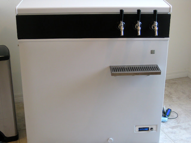
citywok said:I used weather stripping and then installed the collar. The LCD's are wired and working, 80mm dc fan installed. The LCD's took a lot longer than I thought they would, doh.
Awesome!!!!
Flykilbosa
Well-Known Member
rekoob said:This sounds great, can't wait to see some pics.
Here's the original hinges...I attached them to the collar and they are attached to the original top that I built up.


The lid stays put. I actual bought a replacement set of hinges for my model of freezer. That wat i had no need to modify the freezer or lid. I just screwed them into the collar. The hinges are strong enough to hold up the collar and lid. I thought it wasnt but it turned out i had a gas line pulling it down.
like this
So I filled my 10lb co2, connected everything, and the regulator said the tank only had 700 psi (60% on the outer gauge). I ran a keg of water + cleaner through everything, and then a keg of just water, and it was down to 53%, then I turned the freezer on and this morning it's down to 35%, is that drop normal for going from 65f to 38f? I'll play with it later to see if any pieces were leaking, but I'm wondering why the tank started out so low? When I attached the regulator I knocked the valve open about an 1/8th of a turn for about a second, could that have caused it? Is full on the tank really only 700psi or did I get a tank that didn't start full?
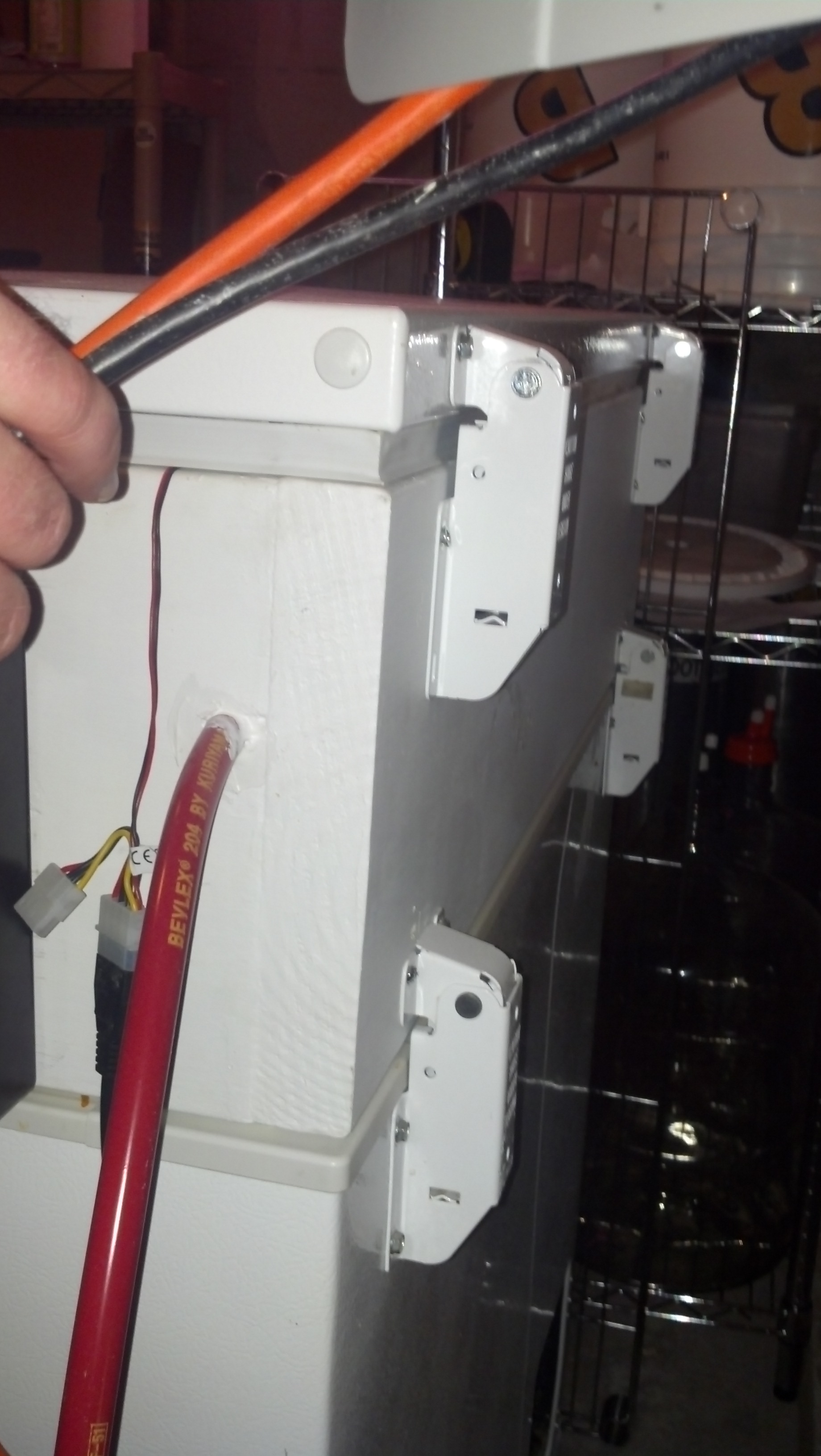
The mini breadboard on the back is an easy spot for connecting the flow sensors, and the black thing dangling in over the side is an ethernet adapter, I ran an ethernet cable but was too lazy to crimp it so that's what i did for the moment. I carved a channel in the back side of the first piece of insulation so I could hide wires, and then added a second piece of insulation for added protection (except for the front, only 1 piece there).
Here's what it looks like now")


The mini breadboard on the back is an easy spot for connecting the flow sensors, and the black thing dangling in over the side is an ethernet adapter, I ran an ethernet cable but was too lazy to crimp it so that's what i did for the moment. I carved a channel in the back side of the first piece of insulation so I could hide wires, and then added a second piece of insulation for added protection (except for the front, only 1 piece there).
Here's what it looks like now
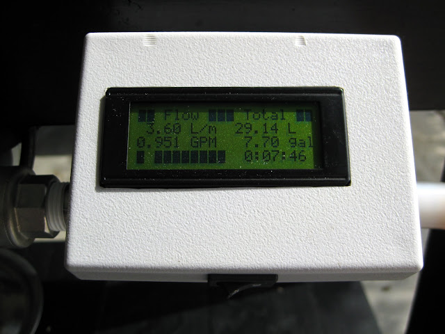
The liquid flow sensors are fairly consistent from pour to pour. The docs online say 450 PPL, but I was pouring a pint of water+cleaner in 275 to 285 pulses, which equates to closer to 600 PPL. The good news is pour to pour it's consistent. We'll see how they do with beer, but so far I'd say things are looking good
Testing the sensors was how I cleaned all of my lines / kegs.
Testing the sensors was how I cleaned all of my lines / kegs.
The high pressure gauges on CO2 tanks are virtually meaningless. They can only tell you the pressure of the gas inside the tank, but the majority of the CO2 is in liquid form. The gauge reads the same number until all the liquid has been converted to gas and then drop rather rapidly. At 70F the gauge should read somewhere around 850 psi, at 30F it should read below 500 psi. The only way to know how much CO2 is left is by weight.So I filled my 10lb co2, connected everything, and the regulator said the tank only had 700 psi (60% on the outer gauge). I ran a keg of water + cleaner through everything, and then a keg of just water, and it was down to 53%, then I turned the freezer on and this morning it's down to 35%, is that drop normal for going from 65f to 38f?
The flow sensors are pretty consistent. I found 450 pulses/L to be more accurate around the 10+ lpm flow rate, and 500 around the 2 lpm flow rate. Again, the orientation affects this number significantly as well.
After a week of use quite a bit of beer has been poured, but i don't know how much because it was crashing on most pours. I fixed that yesterday so going forward it should be accurate, but now I'm fighting with the temp sensors. These things are being a royal pita, and I can't figure them out. I'll have to keep digging.
So far so good!
So far so good!
all it needs is a CO2 sniffer to detect those troublesome little leaks
I figured out the webserver, I had mapped the currently unused 3rd flow sensor to pin 51, which broke it. whoops.
and for a write up of what i've done, which I will update once I finish the arduino, go here:
http://bit.ly/10Vc7wX
and for a write up of what i've done, which I will update once I finish the arduino, go here:
http://bit.ly/10Vc7wX
ChemE
Well-Known Member
I've done a ton of work with the DS18B20s on a OneWire network up to and including writing my own OneWire Code to save space on the microcontroller. My code is WAY less abstracted than trying to wade through the DallasTemperature and OneWire libraries too. Below is some code I wrote to quickly get the fingerprint of a single DS18B20 without having to solder anything. Just shove it into GND, 13, 12 and then shove a 4.7K ohm resistor into 12 and 13 and voila. Even easier is if you have 2 female jumper wires you can use the pins in the ICP port to hold the resistor.
The below code identifies one DS18B20 and polls it every few seconds for a temperature reading and outputs that to the UART all in 1020 bytes of sketch size which is crazy compact. I hope this helps you get a handle on the temperature sensors but if not feel free to ask.
EDIT: The txInt routine at the very bottom is just hanging around from when I was profiling the code execution time and so outputting elapsed microseconds to the UART. The commented out includes at the top are relics from a version of the code that used 3 different files to keep things separated more nicely. That doesn't make for code which is compact and obviously is a real pain to paste here. Still it is nice to work with them as different tabs in the IDE rather than one huge file.
The below code identifies one DS18B20 and polls it every few seconds for a temperature reading and outputs that to the UART all in 1020 bytes of sketch size which is crazy compact. I hope this helps you get a handle on the temperature sensors but if not feel free to ask.
Code:
// Solder-free method of detecting the ROM of a DS18B20 - spread the 3 legs of the sensor wide enough to fit into GND, 13, and 12
// and place the sensor in these pins with the flat side facing the LED on the Uno and the round side facing away from the Uno.
// Then place a 4.7 KΩ resistor in pin 13 and 12.  Unload and open a serial monitor with a baud rate of 9600.
//#include "OneWire.h"    // An extremely space-efficient implementation of selected portions of the OneWire protocol
//#include "simpleTx.h"   // An extremely space-efficient serial debug tool
#include <util/delay.h>

// ====================================================== Pre-Compiler Definitions ======================================================
#define   PowerPin              PB4                       // Pin 12 - we will be using this pin to supply Vcc to the DS18B20
#define   POWER_TEMP_PROBE      PORTB |= _BV(PowerPin)    // Define method for powering the DB18B20
#define   DEPOWER_TEMP_PROBE    PORTB &= ~_BV(PowerPin)   // Define method for depowering the DB18B20
#define   Pin                   PB5    // Set up pin 13 as the data pin
#define   DIRECT_MODE_OUTPUT    DDRB |= _BV(Pin)
#define   DIRECT_MODE_INPUT     DDRB &= ~_BV(Pin)
#define   DIRECT_WRITE_HIGH     PORTB |= _BV(Pin)
#define   DIRECT_WRITE_LOW      PORTB &= ~_BV(Pin)
#define   DIRECT_READ           PINB & _BV(Pin) ? 1 : 0

#define   READROM               0x33  // Read the ROM of a OneWire device; there must only be one OneWire device on the bus!
#define   STARTCONVO            0x44  // Tells device to take a temperature reading and put it on the scratchpad
#define   READSCRATCH           0xBE  // Read EEPROM
#define   SKIPROM               0xCC
#define   MATCHROM              0x55
#define   TEMP_LSB              0
#define   TEMP_MSB              1

#define clk_div 1
#define   DELAY_A               6/clk_div
#define   DELAY_B               64/clk_div
#define   DELAY_C               60/clk_div
#define   DELAY_D               10/clk_div
#define   DELAY_E               9/clk_div
#define   DELAY_F               55/clk_div
#define   DELAY_G               0/clk_div
#define   DELAY_H               480/clk_div
#define   DELAY_I               72/clk_div
#define   DELAY_J               410/clk_div
#define myubbr (16000000/16/9600-1)

int main() {
  uint8_t ROM[8];
  uint8_t scratchPad[2];

  DDRB = B00010000;

  for(;;) {  // Loop forever
    // Perform a OneWire reset pulse
    POWER_TEMP_PROBE;      // This isn't neccesary but I show it to demonstrate how to make the project conserve energy

    simpletx("Presence pulse: ");
    if(reset()) {
      simpletx("Detected\t");
    } else {
      simpletx("Not Detected\t");
    }

    // Attempt to read the ROM, if nothing is present this will return 0x00 for each of the eight bytes
    simpletx("ROM is: ");
    write(READROM);
    for(uint8_t i=0;i<8;i++) {
      ROM[i]=read();
      simpletx("0x");
      txByteAsHex(ROM[i]);
      if (i!=7) simpletx(",");
    }
    simpletx("\t\t");
    DEPOWER_TEMP_PROBE;    // This isn't neccesary but I show it to demonstrate how to make the project conserve energy

    // If we detected a Dallas family sensor, let's go ahead and take a temperature reading
    if (ROM[0]=0x28) {  // The first byte of all dallas sensors is always 0x28
      POWER_TEMP_PROBE;
      reset();
      write(SKIPROM);
      write(STARTCONVO);
      _delay_ms(750);

      reset();
      write(MATCHROM);
      for(uint8_t i = 0; i < 8; i++) write(ROM[i]);
      write(READSCRATCH);
      scratchPad[TEMP_LSB] = read();
      scratchPad[TEMP_MSB] = read();
      reset();
      DEPOWER_TEMP_PROBE;
      uint16_t rawTemperature = (((int16_t)scratchPad[TEMP_MSB]) << 8) | scratchPad[TEMP_LSB];

      simpletx("Temperature: ");
      txRawTempAsFloat(rawTemperature);
      simpletx("F\n");
    }
    _delay_ms(5000);
  }  // End for
}  // End main

static inline uint8_t read() {
  uint8_t r=0;

  noInterrupts();
  for (uint8_t bitMask = 0x01; bitMask; bitMask <<= 1) {
    DIRECT_MODE_OUTPUT;
    DIRECT_WRITE_LOW;
    _delay_us(DELAY_A);
    DIRECT_MODE_INPUT;
    _delay_us(DELAY_E);
    if (DIRECT_READ) r |= bitMask;
    _delay_us(DELAY_F);
  }
  interrupts();
  return r;
}

static inline void write(uint8_t v) {
  noInterrupts();
  for (uint8_t bitMask = 0x01; bitMask; bitMask <<= 1) {
    DIRECT_WRITE_LOW;
    DIRECT_MODE_OUTPUT;
    if (bitMask & v) {
       _delay_us(DELAY_A);
       DIRECT_WRITE_HIGH;
      _delay_us(DELAY_B);
    } else {
      _delay_us(DELAY_C);
      DIRECT_WRITE_HIGH;
      _delay_us(DELAY_D);
    }
  }
  DIRECT_MODE_INPUT;
  DIRECT_WRITE_LOW;
  interrupts();
}

static inline uint8_t reset(void) {
  noInterrupts();
  DIRECT_MODE_INPUT;
  DIRECT_WRITE_LOW;
  DIRECT_MODE_OUTPUT;
  _delay_us(DELAY_H);
  DIRECT_MODE_INPUT;
  _delay_us(DELAY_I);
  uint8_t ret = !(DIRECT_READ);
  interrupts();
  _delay_us(DELAY_J);
  return ret;
}

static inline void simpletx( char * string ) {
  if (UCSR0B != (1<<TXEN0)) { //do we need to init the uart?
    UBRR0H = (unsigned char)(myubbr>>8);
    UBRR0L = (unsigned char)myubbr;
    UCSR0A = 0;//Disable U2X mode
    UCSR0B = (1<<TXEN0);//Enable transmitter
    UCSR0C = (3<<UCSZ00);//N81
    _delay_ms(30);
  }
  while (*string) {
    while ( !( UCSR0A & (1<<UDRE0)) );
    UDR0 = *string++; //send the data
  }
}

static inline void txByteAsHex(uint8_t inp) {
  char snd[3];
  uint8_t tmp = inp>>4;

  if (tmp<10) {
    snd[0]=48+tmp;
  } else {
    snd[0]=55+tmp;
  }

  tmp=inp%16;
  if (tmp<10) {
    snd[1]=48+tmp;
  } else {
    snd[1]=55+tmp;
  }
  snd[2]='\0';
  simpletx(snd);
}

// Converts the raw temperature from a DS18B20 directly to a string containing the temperature in °F with 1 decimal place
// avoids unnecessary floating point math, float variables, and casts, and 32-bit math
// TODO: May not work properly with temperatures below 32°F
static inline void txRawTempAsFloat(uint16_t raw) {
  char buffer[5];

  //uint32_t temp = (raw*1125ul+320000ul)/1000ul;  // Keeps all 4 decimal places but uses 32-bit math
  uint16_t temp = (9*raw)/8+320;                   // Keeps only 1 decimal place but uses 16-bit math

  uint8_t decimalPos = 2;  // default case of a temp between 0 and 99.9
  uint8_t nullPos = 4;     // default case of a temp between 0 and 99.9

  if(temp>1000) {  // We're looking at a positive number with three digits
    decimalPos = 3;
    nullPos = 5;
  }

  for(int8_t i=nullPos;i>-1;i--) {
    if (i==decimalPos) {
      buffer[i] = '.';
    }
    else if (i==nullPos) {
      buffer[i] = '\0';
    }
    else {
      buffer[i]= temp % 10 + '0';
      temp /= 10;
    }
  }

  simpletx(buffer);
}

static inline void txInt(long inp) {
  long temp = inp;
  uint8_t numChars=0;
  boolean isNegative=false;

  // Check to see if there is a negative sign
  if(temp<0){
    isNegative=true;
    numChars++;
    temp*=-1;
  }

  do {
    numChars++;
    temp /= 10;
  } while ( temp );
  char buf[numChars];

  // Write the negative sign if present and the terminating null character
  temp=inp;
  buf[numChars]=0;
  if(isNegative) {
    temp*=-1;
    buf[0]='-';
  }

  int i = numChars - 1;
  do {
      buf[i--] = temp%10 + '0';
      temp /= 10;
  } while (temp);

  simpletx(buf);
}
EDIT: The txInt routine at the very bottom is just hanging around from when I was profiling the code execution time and so outputting elapsed microseconds to the UART. The commented out includes at the top are relics from a version of the code that used 3 different files to keep things separated more nicely. That doesn't make for code which is compact and obviously is a real pain to paste here. Still it is nice to work with them as different tabs in the IDE rather than one huge file.
This whole project is awesome! I have been thinking about doing something similar. I don't have any experience with Arduino, but I was initially thinking this might be a simple place to start. After seeing your frustrations, I'm rethinking doing it from scratch...might just end up copying your code/process if you don't mind.
My initial idea was to use load sensors rather than flow. I was thinking I would hack into an ebay postal scale and tare the weight of the keg out. Then I would display remaining beer as a percentage rather than a number of pints (since I don't always pour a pint). Any reason other than space that wouldn't work?
I like the web interface a lot! I was thinking about creating a twitter account for each keg and tweeting commands to the displays, but your solution is a lot cleaner.
Can't wait to see the finished product!!!
EDIT: Is it possible the flow sensors would get gummed up with sugar or trub over time?
This whole project is awesome! I have been thinking about doing something similar. I don't have any experience with Arduino, but I was initially thinking this might be a simple place to start. After seeing your frustrations, I'm rethinking doing it from scratch...might just end up copying your code/process if you don't mind.
My initial idea was to use load sensors rather than flow. I was thinking I would hack into an ebay postal scale and tare the weight of the keg out. Then I would display remaining beer as a percentage rather than a number of pints (since I don't always pour a pint). Any reason other than space that wouldn't work?
I like the web interface a lot! I was thinking about creating a twitter account for each keg and tweeting commands to the displays, but your solution is a lot cleaner.
Can't wait to see the finished product!!!
EDIT: Is it possible the flow sensors would get gummed up with sugar or trub over time?
Please do, if you have any questions about how I did anything let me know. I haven't actually worked on the temp sensors in a while, but everything else has been working great so far. The 2 kegs on tap are both down to 25% or so, so in a couple weeks i should have a pretty good idea of how accurate everything is.
Thanks!
citywok, first thanks for the great write up. I hope you're serious about helping a beginner. My aduino, flowmeters and 1 wire temp sensors and touch screen display arrived today. I have never even seen an arduino before much less know any code (other than html). I hope to begin my journey sometime over the next few days. Questions to follow.
Ok, I've decided to pull the trigger based on your build. This is just too awesome to pass up. A couple of questions.
This whole build is so awesome!!! :rockin:
- Is your Arduino sketch available somewhere? I am a total Arduino beginner, so it would be great to have something to work off of.
- Is an Arduino Mega R3 necessary? I found this one on Amazon, but an Uno is half the price (like here). I'm guessing I definitely need the Ethernet Shield and a breadboard (looks like you used a 170 point like this one). The ethernet shield is hardwired to your home network at all times, right?
- One adjustment I'm interested in making eventually is to put a weight sensor under the CO2 tank to actually have an estimate of how much is left. Is that something I can add on later, once I get the other stuff working?
- I was thinking I might use 4-line LCDs (these) with the beer name on line 1, style on line 2, ABV and IBUs on line 3, and amount (or percent) remaining on line 4. It seems like this would be a pretty easy adjustment to the webserver code, right?
This whole build is so awesome!!! :rockin:
Last edited by a moderator:
Wow.... Cool project. Subscribed!
Ok, I've decided to pull the trigger based on your build. This is just too awesome to pass up. A couple of questions.
- Is your Arduino sketch available somewhere? I am a total Arduino beginner, so it would be great to have something to work off of.
- Is an Arduino Mega R3 necessary? I found this one on Amazon, but an Uno is half the price (like here). I'm guessing I definitely need the Ethernet Shield and a breadboard (looks like you used a 170 point like this one). The ethernet shield is hardwired to your home network at all times, right?
- One adjustment I'm interested in making eventually is to put a weight sensor under the CO2 tank to actually have an estimate of how much is left. Is that something I can add on later, once I get the other stuff working?
- I was thinking I might use 4-line LCDs (these) with the beer name on line 1, style on line 2, ABV and IBUs on line 3, and amount (or percent) remaining on line 4. It seems like this would be a pretty easy adjustment to the webserver code, right?
This whole build is so awesome!!! :rockin:
1. I started with zero arduino experience, and very limited electronics experience (high school electronics class, a very long time ago). I started out by building everything one piece at a time, and learning how each component worked on the kitchen table before I was ready for final assembly. PM me your email address and I'll send you my sketch.
2. It isn't, but in order to have enough pins to run 3 LCD's directly off the board you definitely would. Everything I read said you could only have 2 analog sensors on an Uno, so I bought the Mega, but I don't think that makes a difference with the flow sensors I ended up using. Maybe it does, I'm no arduino expert
I'm using the ethernet shield, connected to a wireless extender because I already had it, and this way I can use it direct attached when it's near a jack.
3. Sure, just add the wire and modify the sketch
4. The webserver code is independent of the LCD's. The webserver code is called at each loop, and then the LCD's are drawn by the main loop, and then there is a couple second pause. In arduino land the loop() is called over and over until forever, so if you want it to run every few seconds you add a delay/sleep.
As for the breadboard I used two. I used a 400 point where I connected all the LCD's / everything, and a 170point mini board on the other side where I terminated the flow sensors. This way when the lid is opened the wires don't get pulled around as much, and you don't need to run +/-/data for each sensor, just the data, and use common +/-. It's not necessary, but it made life easier.
Last edited by a moderator:
citywok, first thanks for the great write up. I hope you're serious about helping a beginner. My aduino, flowmeters and 1 wire temp sensors and touch screen display arrived today. I have never even seen an arduino before much less know any code (other than html). I hope to begin my journey sometime over the next few days. Questions to follow.
I had never seen one either, but I do know how to code.
I haven't tackled the temp sensor, I've been busy doing other things (*cough* drinking). lol.
If you have any questions feel free to ask. If you want to see my sketch PM me your email address and I'll share it with you.
FuzzeWuzze
I Love DIY
Does the flow sensor affect the beer at all?
I can see something that big bit of plastic giving a plastic taste to the beer in the line for hours or days that can happen between pours ...
I can see something that big bit of plastic giving a plastic taste to the beer in the line for hours or days that can happen between pours ...
Does the flow sensor affect the beer at all?
I can see something that big bit of plastic giving a plastic taste to the beer in the line for hours or days that can happen between pours ...
I haven't noticed a difference. If it does affect the taste it would probably only be for the ounce that is in contact with it, and it gets diluted across a whole beer. Maybe my palate isn't sensitive enough, or maybe it isn't happening.
After several months I can report that I haven't had any issues with the flow sensors affecting the beer, but I've been flushing the lines quite a bit with each keg swap and no keg has lasted more than 2 months.
The sensors aren't very accurate for 1oz pours, but if you pour 6oz or more it's pretty spot on once you calibrate it.
So far so good
The sensors aren't very accurate for 1oz pours, but if you pour 6oz or more it's pretty spot on once you calibrate it.
So far so good
boombrewer
Well-Known Member
I was doing research for building a temp controller for a fermenter but this is awesome! Now I want to build something like this for my kegorator AND temp controllers for my fermenter (still to be built). Can you PM me your sketch and code? I'm starting out the same place you did minus a high school electronics class. I'm hoping my limited understanding of electricity is enough to get me through.
Jthornburgh
Well-Known Member
- Joined
- Oct 1, 2015
- Messages
- 87
- Reaction score
- 9
I would appreciate the sketch as well.
BrewingChemist
Well-Known Member
I'd love the sketch also!
Similar threads
- Replies
- 7
- Views
- 847
- Replies
- 3
- Views
- 298
- Replies
- 8
- Views
- 508
