• Please visit and share your knowledge at our sister communities:
  • If you have not, please join our official Homebrewing Facebook Group!

    Homebrewing Facebook Group

Another P-J Diagram: BIAB 5500W Single Vessel Single Pump, Illuminated Switches

Homebrew Talk

Help Support Homebrew Talk:

This site may earn a commission from merchant affiliate links, including eBay, Amazon, and others.

johnodon

Well-Known Member
Joined
Aug 23, 2010
Messages
643
Reaction score
21
Location
Douglassville, PA
UPDATE: This wiring diagram has gone through a few different revisions since this thread had started...mainly around the wiring of the switches. I have updated the OP with the latest (and hopefully) final diagram (from post #17).

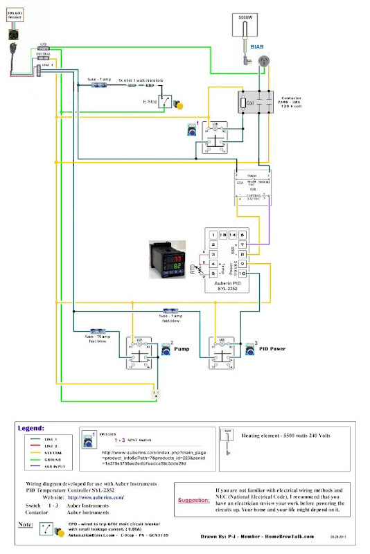
I am in the process of moving from propane to electric. P-J has been an incredible help (behind the scenes) with the control panel wiring. I thought that there may be others out there that want to build a similiar system so I figured I would post the wiring diagram that P-J provided to me (hope you don't mind P-J).

BIAB, 5500W, Single Vessel, Simgle Pump with these illuminated switches from Auberins: http://www.auberins.com/index.php?m...id=223&zenid=ab8093581ddb0f3995d65247c34d338a


I know I thanked you many times via PM P-J, but, once again...THANK YOU!!!

John
 
This is exactly what i have been looking for.

Did he also supply you with his brew parts order list for this?

Are you planning on recirculating during the mash with your pump?
 
Brew parts as in the control panel parts? Or actual kettle, pump, etc.?

Yep...I plan on recircing during the entire length of the mash.

John
 
P-J,

In our conversations I had asked you where I need to have 10ga wire and you answereed:

You will need to use #10 wire for the power going to the element through the SSR & contactor. All of the balance of the wiring can be done with #14 wire.

Can you take a quick look at the moddified diagram below and let me know if I missed any?

Auberin-wiring1-a4-5500w-BIAB-30d4.jpg


Thanks!

John
 
That's a great setup! I like it a lot and it's similar to Psych's but with a pump, which is what I'm planning on using (eventually).

I just have to get on the horse and start ordering parts. What were you going to use for an enclosure?
 
That's a great setup! I like it a lot and it's similar to Psych's but with a pump, which is what I'm planning on using (eventually).

I just have to get on the horse and start ordering parts. What were you going to use for an enclosure?

I am using the project box on Auberins: http://www.auberins.com/index.php?m...id=143&zenid=07ab2eb8b53d7fe8f8cf800855feaee4

It is is a bit tight but since I don't have too many things going on, the space is managable. It is also nice because it already has the hole for the PID cut out. The only add shaped hole I will need to cut now is for the outlet for the pump.

These are the illuminated switches: http://www.auberins.com/index.php?m...id=223&zenid=07ab2eb8b53d7fe8f8cf800855feaee4

They are a bit pricey but I like 'em!! :) I just cut the holes and mounted them a few minutes ago.

John
 
Another thought for you. Save a little space and cut the tabs at the red lines and then use the cover mount screw holes to mount it in your control box.

outlet.jpg
 
Another thought for you. Save a little space and cut the tabs at the red lines and then use the cover mount screw holes to mount it in your control box.

outlet.jpg


That is an excellent idea. I really wanted to mount both the 240v and the 120v on the back of the control box (the Auber one) but it would have been really tight. Actually, I don't think it would have happened at all. If I cut those legs I think I can make both fit.

Thanks again and keep the suggestions coming! :)

John
 
OK P-J...couple more wiring questions (ignore my current wiring...I got ahead of myself)...

Regarding the illuminated switches
Each has a total of 6 posts. 4 posts pretty much in a retangular pattern (shown as 24 and 14 in the pic and the same on the underside but different #s) and 2 posts separated from that rectangle (top right next to the yellow tab).

IMG_2692.jpg


Using the PUMP SWITCH as an example, does LINE 1 go to any one of the 4 posts in a rectangular configuration and the a separate line goes from one of the offset posts to HOT post on the receptacle?

And..regarding the contactor...

Are the screw down posts for the 10ga (240v) wire (red wire in the pics) and the spades on the sides for the 120v (coil) wires (white and black wires with the blue plastic)? If so, are all 240v posts the same and all 120v posts the same...meaning orientation doesn't matter?

Thanks,

John

IMG_2694.jpg
 
OK P-J...couple more wiring questions (ignore my current wiring...I got ahead of myself)...

Regarding the illuminated switches
Each has a total of 6 posts. 4 posts pretty much in a retangular pattern (shown as 24 and 14 in the pic and the same on the underside but different #s) and 2 posts separated from that rectangle (top right next to the yellow tab).

Using the PUMP SWITCH as an example, does LINE 1 go to any one of the 4 posts in a rectangular configuration and the a separate line goes from one of the offset posts to HOT post on the receptacle?

And..regarding the contactor...

Are the screw down posts for the 10ga (240v) wire (red wire in the pics) and the spades on the sides for the 120v (coil) wires (white and black wires with the blue plastic)? If so, are all 240v posts the same and all 120v posts the same...meaning orientation doesn't matter?

Thanks,

John
For the switch: You need to read this Switch Manual for the terminal designations and connections.

Regarding the contactor: The terminals on the side (white and black wires) are the coil connections.

The connections where you have the two red wires are the posts for the input of the 2 phases. The output terminals are on the other side of the contactor where you have both black wires connected. The way you have it set up you will absolutely no power being delivered to the element.

In other words - you should have a black and a red wire connected to those terminals. The same for the output terminals. (Based on the diagram that I drew for you.)

I hope this helps you.

BTW, Do you have an ohm meter? With that you can test out you wiring before powering up.

P-J
 
P-J,

I took a shot at wiring the switches using the manual on the Auber site. Here is a pic of how they show it to be wired. However, I think this is intended for a 240v application:

typical.jpg


So, I simply removed one of the hot wires from the equation since each switch will have only a 120v load:

120.jpg


Here is what I came up with in the end:

Auberin-wiring1-a4-5500w-BIAB-30d4-v2.jpg


Is my thinking correct? My concern is that I was talking to a electrical engineer (in training) and he drew the diagram a little differently...like below...where he tied the neutral back into the switch LED:

common.jpg


I probably should not have doubted him but it happens! :)

Here is the diagram if I follow his instructions:

CopyofAuberin-wiring1-a4-5500w-BIAB-30d4-jons.jpg


TIA!

John
 
John,

You have it right with your last illustration.

Here is an updated drawing for you.
(As always, click on the image for a full scale diagram printable on Tabloid paper 11" x 17")


P-J
 
Awesome P-J...thank you very much.

As you can see, I took the e-stop out as automationdirect has them back ordered. I figured I can do without it for the time being and add it later. Thwy have the blackon in stock but I really want the yellow to stand out. :)

I'm in MI for a week so I can't work on my panel...even though it is calling to me. :(

Thanks again!

John
 
Pretty cool. A local brew buddy turned me on to the idea of BIAB. This seems like it would be awesome. I will also through out there that I think shorting to ground for an E-Stop is a bad idea. It works in theory... but isn't really the way to do it. Basically you should have a contactor/relay that powers itself... the E-Stop should cut the coil current on the contactor/relay which will kill the device. Relying on an outside device for E-Stop safety is generally considered bad practice.

And do you have diagrams/pictures of the rest of the setup? (The pumps, flow, etc)?
 
...
I will also through out there that I think shorting to ground for an E-Stop is a bad idea.
...
I imagine that you also think it is a bad idea to press the test button on the GFCI circuit breaker.

The E-Stop circuit does not provide a short to ground. It provides a leakage current of 0.06A to ground. It is approxomately the same current that is used when pressing the test button.
 
I imagine that you also think it is a bad idea to press the test button on the GFCI circuit breaker.

The E-Stop circuit does not provide a short to ground. It provides a leakage current of 0.06A to ground. It is approxomately the same current that is used when pressing the test button.

No. I don't think it is bad to press the test button. I am not debating that it works. I am stating that from the point of view of safety an emergency stop should not rely on items outside of the control panel to work. This is coming from the perspective of someone who has actually worked on automation systems, etc. It is my $0.02, you can take it or leave it.
 
Thank you. I WILL leave it.!!!

From the point of view for safety, When the power is disabled from the source, there is NO power in the control panel. If it is 'interlocked' within the panel, there is still power available within the panel and the circuits AND lines feeding it.

You have your opinions. I have mine.

Done.!

BTW: Nice attempt at a slam:
This is coming from the perspective of someone who has actually worked on automation systems, etc.

Congratulations!
 
Hey John thanks for all the info this is very similar to what I was thinking.

Do you have any pics of the system or the build?

Cheers
 
Still need to install the element and finish the wiring. I plan on doing that this weekend. Once done, I will post pics.

John
 
Got my control box finished...

Installed the Spa Panel...

Just performed my first dry run. To my surprise, everything worked on the first shot! :)

I am running an auto-tune on the PID right now @ 170F. Pics to come later...

John
 
I know I have been slacking. A few people have PM'd me asking for more details. I plan on taking some pics tonight and starting a new thread which details all of the components (kettle, control box, pump, etc.) with a parts list the best I can remember.

Stay tuned...

John
 
I am looking at doing a build very similar to this. But, my access to a 240V is kind of limited without pulling out the stove and wiring there. So in the mean time I am planning on running off a 120V GFI protected socket. (This should be fine, since for now I am only doing 2.5 gallons.) However, I would like to plan for the future and have everything wired up so that I can use 240 in the future and just have to swap out the element.

My question is can I wire up my control panel according to the diagram below, using a 120V, 2000W element. The SSR and contractor would be 240V, so when I do want to move to 240 I can just run the second hot line to contractor.

(Edit: Sorry for the hijack.)

240to120-BIAB.jpg
 

Latest posts

Back
Top