jbartz
Member
Hello Everyone,
I have read this forum for a long time and have yet to post something. I can't begin to say how much I appreciate everything I've read here.
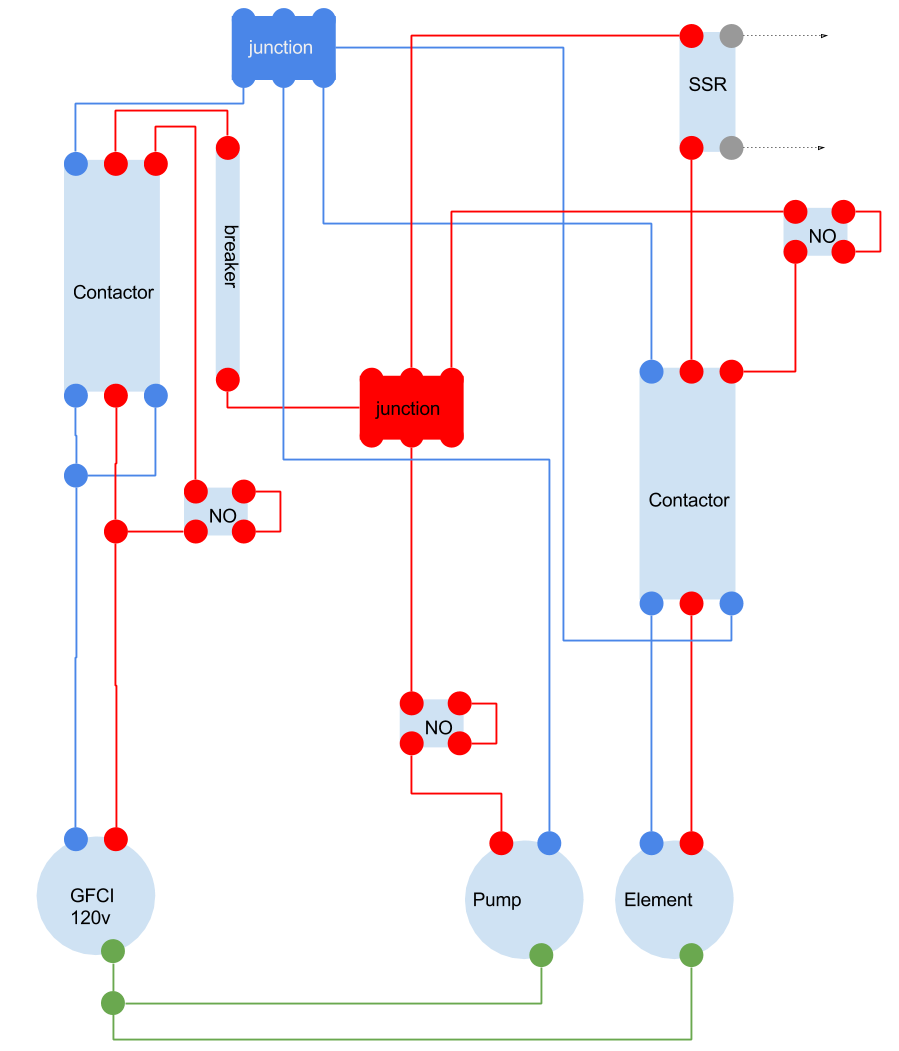
I am not an expert on electrical diagrams so please forgive the crudeness of the Google drawing. I bought this equipment a while ago but finally got around to putting it together.
This is based off the diagram from the 120v PID kit from ebrewsupply.com but uses a single pump, no emergency stop and no PID (a potentiometer instead, not shown).
My main concerns are the beginning of the diagram near the GFCI, the lines appear to cross. My understanding of electrical diagrams is this means they just follow the same path; a junction should be represented by a circle. In my diagram I represented them as a junction but that might be incorrect. Does this matter? Should the wires start from the GFCI or do they need a junction at a split?
The output from the SSR is not included in the diagram, but it's just going to a potentiometer (included in equipment list below).
I have also not included fuses in the diagram but I will likely include one in front of the SSR and the pump.
The equipment in the diagram is:
Contactors: http://www.ebrewsupply.com/240v-2p-25a-110v-coil-din-rail-contactor/
Breaker: http://www.ebrewsupply.com/20a-single-pole-breaker-new-version/
NO switches: http://www.ebrewsupply.com/red-led-push-button-2-way-switch/
SSR: http://www.auberins.com/index.php?main_page=product_info&cPath=53&products_id=353
Junctions: http://www.ebrewsupply.com/din-rail-terminal-block/
Any advice folks could give would be very much appreciated.
Regards,
Jason


