Ok I've done the above and have taken my soldering skills to the next level! Those surface mounts are sooooo small. Now I'm diassembling some of my Fermentrack/BrewPi/Rpi/Uno prevoius test setup to wire into the Mini but I've got 3 leads from the DS18b20s but only see where the GND and Data (D6)go in the RJ45 plug but not the one remaining one? The post you point to is for a RJ11 plug.All of the resistors R1,R2,R3,R4,R5 are all the same. 10k Resistor 805 SMD( the number 805 represents the physical size of the Surface Mount Device)
Q1,and Q2 are both BSS138 MOSFET 805 SMD
C1 is 100uF 1206 Capacitor (Optional)1206 SMD ( different size than 805)
JP1 is for the buzzer. (I don't use it) and uses a 2 pin header
01,02 is for power in and uses a 2-Pin 5mm Pitch Screw Terminal
LCD and Relay uses four pin header
This post and the one below it explains the pin out for the RJ-45 jack.https://www.homebrewtalk.com/forum/...no-arduino-needed.586476/page-54#post-8446806
You are using an out of date browser. It may not display this or other websites correctly.
You should upgrade or use an alternative browser.
You should upgrade or use an alternative browser.
Native ESP8266 BrewPi Firmware - WiFi BrewPi, no Arduino needed!
- Thread starter Thorrak
- Start date

Help Support Homebrew Talk:
This site may earn a commission from merchant affiliate
links, including eBay, Amazon, and others.
Ok I've done the above and have taken my soldering skills to the next level! Those surface mounts are sooooo small. Now I'm diassembling some of my Fermentrack/BrewPi/Rpi/Uno prevoius test setup to wire into the Mini but I've got 3 leads from the DS18b20s but only see where the GND and Data (D6)go in the RJ45 plug but not the one remaining one? The post you point to is for a RJ11 plug.
Are you using the RJ-45 breakout board, or are you attempting to directly splice the temperature sensors onto cables of some sort?
The RJ-11 boards are intended if you're directly splicing, as that's how the old-school telephone splitters worked, which means the hardware to connect everything is generally pretty available. The RJ-45 boards are intended for use with a breakout board, due to the wide availability of RJ-45 cables (as opposed to RJ-11 ones, which are becoming more scarce)
Nevermind. I just checked continuity from the 3.3v to all the RJ45 points and the 3rd from the left on the plug or second from left contact in the bottom row on the board has continuity to 3.3V Then I saw the trace on the bottom view! Doh! Sorry.Ok I've done the above and have taken my soldering skills to the next level! Those surface mounts are sooooo small. Now I'm diassembling some of my Fermentrack/BrewPi/Rpi/Uno prevoius test setup to wire into the Mini but I've got 3 leads from the DS18b20s but only see where the GND and Data (D6)go in the RJ45 plug but not the one remaining one? The post you point to is for a RJ11 plug.
Using the RJ45 board. Attempting to flash now with Fermentrack. On my 3rd attempt. First two attempts returned a code 2. This time I've got the RPi on ethernet instead of Wifi to see if that helps the flash.
Using the RJ45 board. Attempting to flash now with Fermentrack. On my 3rd attempt. First two attempts returned a code 2. This time I've got the RPi on ethernet instead of Wifi to see if that helps the flash.
The internet connection shouldn’t matter, as the firmware is downloaded before the flash process starts. Check the size of the power adapter for the Pi (and disconnect the temp sensors before flashing to (slightly) decrease power usage) as insufficient power to run everything is the #1 culprit I’ve encountered when having flash issues.
If that doesn’t work, post a photo of the ESP8266 you’re flashing and I can see if there might be something else to try. (You can also try the qio/dio flash modes if you want)
update Failed again got thisUsing the RJ45 board. Attempting to flash now with Fermentrack. On my 3rd attempt. First two attempts returned a code 2. This time I've got the RPi on ethernet instead of Wifi to see if that helps the flash.
esptool.py v2.5.1
Serial port /dev/ttyUSB0
Connecting........_____....._____....._____....._____....._____....._____....._____
A fatal error occurred: Failed to connect to Espressif device: Timed out waiting for packet header


![Craft A Brew - Safale S-04 Dry Yeast - Fermentis - English Ale Dry Yeast - For English and American Ales and Hard Apple Ciders - Ingredients for Home Brewing - Beer Making Supplies - [1 Pack]](https://m.media-amazon.com/images/I/41fVGNh6JfL._SL500_.jpg)
$6.95 ($17.38 / Ounce)
$7.47 ($18.68 / Ounce)
Craft A Brew - Safale S-04 Dry Yeast - Fermentis - English Ale Dry Yeast - For English and American Ales and Hard Apple Ciders - Ingredients for Home Brewing - Beer Making Supplies - [1 Pack]
Hobby Homebrew

$53.24
1pc Hose Barb/MFL 1.5" Tri Clamp to Ball Lock Post Liquid Gas Homebrew Kegging Fermentation Parts Brewer Hardware SUS304(Gas MFL)
Guangshui Weilu You Trading Co., Ltd


$33.99 ($17.00 / Count)
$41.99 ($21.00 / Count)
2 Pack 1 Gallon Large Fermentation Jars with 3 Airlocks and 2 SCREW Lids(100% Airtight Heavy Duty Lid w Silicone) - Wide Mouth Glass Jars w Scale Mark - Pickle Jars for Sauerkraut, Sourdough Starter
Qianfenie Direct


$39.22 ($39.22 / Count)
Brewer's Best Home Brew Beer Ingredient Kit - 5 Gallon (Mexican Cerveza)
Amazon.com

$20.94
$29.99
The Brew Your Own Big Book of Clone Recipes: Featuring 300 Homebrew Recipes from Your Favorite Breweries
Amazon.com


$479.00
$559.00
EdgeStar KC1000SS Craft Brew Kegerator for 1/6 Barrel and Cornelius Kegs
Amazon.com

$28.98
Five Star - 6022b_ - Star San - 32 Ounce - High Foaming Sanitizer
Great Fermentations of Indiana
$53.24
1pc Hose Barb/MFL 1.5" Tri Clamp to Ball Lock Post Liquid Gas Homebrew Kegging Fermentation Parts Brewer Hardware SUS304(Gas MFL)
yunchengshiyanhuqucuichendianzishangwuyouxiangongsi

$176.97
1pc Commercial Keg Manifold 2" Tri Clamp,Ball Lock Tapping Head,Pressure Gauge/Adjustable PRV for Kegging,Fermentation Control
hanhanbaihuoxiaoshoudian


$7.79 ($7.79 / Count)
Craft A Brew - LalBrew Voss™ - Kveik Ale Yeast - For Craft Lagers - Ingredients for Home Brewing - Beer Making Supplies - (1 Pack)
Craft a Brew


$10.99 ($31.16 / Ounce)
Hornindal Kveik Yeast for Homebrewing - Mead, Cider, Wine, Beer - 10g Packet - Saccharomyces Cerevisiae - Sold by Shadowhive.com
Shadowhive


$58.16
HUIZHUGS Brewing Equipment Keg Ball Lock Faucet 30cm Reinforced Silicone Hose Secondary Fermentation Homebrew Kegging Brewing Equipment
xiangshuizhenzhanglingfengshop

$22.00 ($623.23 / Ounce)
AMZLMPKNTW Ball Lock Sample Faucet 30cm Reinforced Silicone Hose Secondary Fermentation Homebrew Kegging joyful
无为中南商贸有限公司


I tried the default load same fail.The internet connection shouldn’t matter, as the firmware is downloaded before the flash process starts. Check the size of the power adapter for the Pi (and disconnect the temp sensors before flashing to (slightly) decrease power usage) as insufficient power to run everything is the #1 culprit I’ve encountered when having flash issues.
If that doesn’t work, post a photo of the ESP8266 you’re flashing and I can see if there might be something else to try. (You can also try the qio/dio flash modes if you want)
I ordered Smart Electronics D1 mini - Mini NodeMcu 4M bytes Lua WIFI Internet of Things development board based ESP8266 this is a photo of what it looks like
Could I have screwed up the soldering? As I was trying to troubleshoot what ended up being a bad usb cable I was checking voltages. I got the 5 v readings but couldn't find any 3.3 v points I was getting like 0.119 v at those points.
CadiBrewer
Well-Known Member
Try taking the ESP off of your soldered board and flashing it without anything else hooked up. Also, I don't know the schematic of that particular PCB board, but it looks like you're missing a capacitor at C1.
I'll pick this up tomorrow as it is past midnight here.Could I have screwed up the soldering? As I was trying to troubleshoot what ended up being a bad usb cable I was checking voltages. I got the 5 v readings but couldn't find any 3.3 v points I was getting like 0.119 v at those points.
Bigdaddyale
Well-Known Member
C1 is optional, I think it was used to try and help with screen scrambleTry taking the ESP off of your soldered board and flashing it without anything else hooked up. Also, I don't know the schematic of that particular PCB board, but it looks like you're missing a capacitor at C1.
Try taking the ESP off of your soldered board and flashing it without anything else hooked up. Also, I don't know the schematic of that particular PCB board, but it looks like you're missing a capacitor at C1.
If you haven't been disconnecting the rest of your build, do that (flash the ESP8266 with nothing else connected)
The capacitor is optional, and only lightly recommended. Most of my builds don't have it - as @Bigdaddyale noted, it was an attempt to fix screen scrambling. It didn't fix 100% of the instances, and was replaced with a software fix instead.
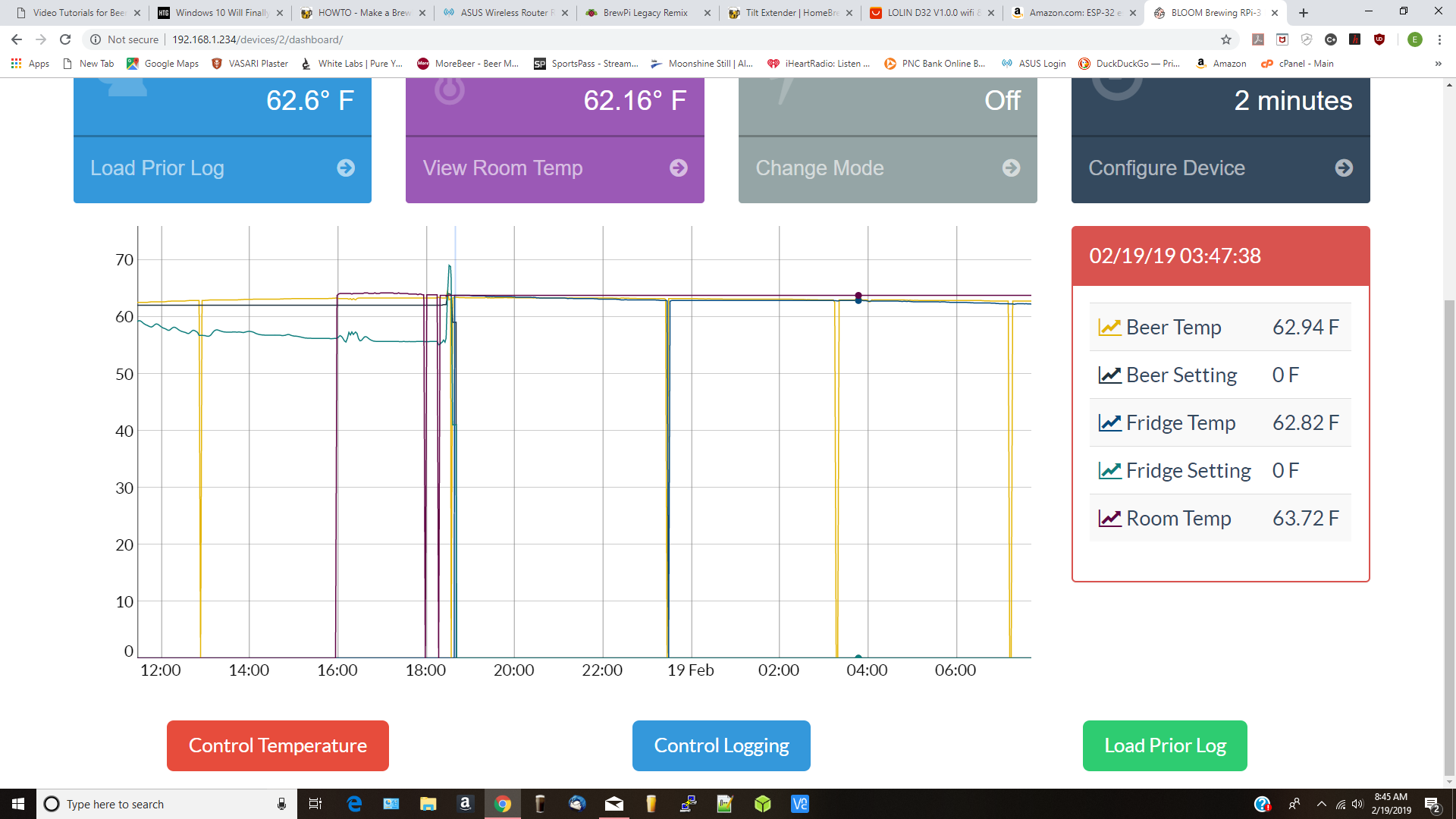
What causes these Graph "dips". I would guess a temporary loss of logging, or a conductivity issue with the sensors? They do run about 40-50 feet, with #18 copper wire from the thermowells to the Pi.
To my eyes, it looks like a sensor is dropping out (which would make sense with the length of wire you’re using). What size pull-up resistor are you currently using?
It looks like ALL of the sensors are experiencing drop-outs.
40 feet of 18 gauge is a lot of distance - and a lot of copper for signals that could travel on 30 gauge. Is it at least twisted pair?
Cheers!
40 feet of 18 gauge is a lot of distance - and a lot of copper for signals that could travel on 30 gauge. Is it at least twisted pair?
Cheers!
CadiBrewer
Well-Known Member
With the ESP8266 build, why do you need to have your sensors travel that far over copper?
Unfortunately I did not heed @Bigdaddyale 's earlier post of not soldering in the ESP8266 so instead of unsoldering I built another. I want four eventually I tried it again on the RJ45 board with just usb to RPi no 5v same no go. But this one I could uplug and so I did and flashed success!If you haven't been disconnecting the rest of your build, do that (flash the ESP8266 with nothing else connected)
The capacitor is optional, and only lightly recommended. Most of my builds don't have it - as @Bigdaddyale noted, it was an attempt to fix screen scrambling. It didn't fix 100% of the instances, and was replaced with a software fix instead.
Well success was short lived. Plugged the chip into the RJ45 pcb unplugged the usb wired up the 5v and......nothing. No little blue lights nothing. 5.5v to all the right places. Pretty much 10k across all the right points but only 0.11 v where I think 3.3v should be. Bad mosfets? Suggestions anyone?Unfortunately I did not heed @Bigdaddyale 's earlier post of not soldering in the ESP8266 so instead of unsoldering I built another. I want four eventually I tried it again on the RJ45 board with just usb to RPi no 5v same no go. But this one I could uplug and so I did and flashed success!
With the ESP8266 build, why do you need to have your sensors travel that far over copper?
I don't have an ESP8266 build. Not sure why this would matter? The Sensors are One-Wire address, (VCC, DATA, Ground), and go back to the Arduino.
I'm an HVAC Tech., so I have tons of solid copper thermostat wire around. Its Solid, with a beefy #18 gauge, so it should not have much resistance...? for such a small currant transmission.... I don't know from any experience, what drops over distance that One may see, looking at temperature probe communication lines, such as my set up.
I know 24 volts DC is not anywhere near what we see on these wires, so that's why I'm not sure WTH, I'm talking about.

My Resistor is a 4.7 kohm 1/2 watt carbon-film. Which I also do not know WTH this does...just know it made my Pi's work for the past 3 years, so I never questioned it, until you much-more-knowledgeable guy's asked me!
OK, so "NO ARDUINO NEEDED" how this Thread starts off at Post #1, but I never look at directions....just jump in AZZ first !
Reading Lee Bussy's post #4, it seems to me now that my Arduino and the copper wires, are NOT needed... Maybe I should just take the copper to the Scrap Yard, smoke the 2 Bucks, and flash a ESP8266 board when I get home ? !
Thanks for taking the time to chime in on my Quest for an Upgrade in the Membrane!
Last edited:
I don't have an ESP8266 build. Not sure why this would matter? The Sensors are One-Wire address, (VCC, DATA, Ground), and go back to the Arduino.
I'm an HVAC Tech., so I have tons of solid copper thermostat wire around. Its Solid, with a beefy #18 gauge, so it should not have much resistance...? for such a small currant transmission.... I don't know from any experience, what drops over distance that One may see, looking at temperature probe communication lines, such as my set up.
I know 24 volts DC is not anywhere near what we see on these wires, so that's why I'm not sure WTH, I'm talking about.
My Resistor is a 4.7 kohm 1/2 watt carbon-film. Which I also do not know WTH this does...just know it made my Pi's work for the past 3 years, so I never questioned it, until you much-more-knowledgeable guy's asked me!
OK, so "NO ARDUINO NEEDED" how this Thread starts off at Post #1, but I never look at directions....just jump in AZZ first !
Reading Lee Bussy's post #4, it seems to me now that my Arduino and the copper wires, are NOT needed... Maybe I should just take the copper to the Scrap Yard, smoke the 2 Bucks, and flash a ESP8266 board when I get home ? !
Thanks for taking the time to chime in on my Quest for an Upgrade in the Membrane!
I think the point around the ESP8266 question was that if you had an ESP8266, presumably your controllers were connected via WiFi and could therefore be placed near your fermenters. For most setups, you could then get away with ~6ft cables on the DS18b20s which should reduce the potential that the run length would interfere.
A 4.7 kohm resistor is what the DS18b20 spec sheet calls for - but if you happened to follow my instructions for the ESP8266 build, you might have used a 10k resistor instead. That was because I was lazy when sourcing resistors and wanted all the resistors to be the same - 4.7k is actually the better (correct) one to use. The higher the value of the pullup resistor the longer it will take the voltage to reach "high" after being pulled low by the device which is a problem for longer cable runs. I don't have any experience with (or knowledge of, or recommend...) smaller resistors - its possible that swapping the 4.7k for a 4k or 3k could help in your situation -- but it's also equally possible that it would break your sensors or prevent them from working entirely.
If you're looking to go as wireless as possible I do recommend going down the ESP8266 route -- though if you go down that route, I highly recommend buying D1 minis from the source, rather than knock offs.
Well success was short lived. Plugged the chip into the RJ45 pcb unplugged the usb wired up the 5v and......nothing. No little blue lights nothing. 5.5v to all the right places. Pretty much 10k across all the right points but only 0.11 v where I think 3.3v should be. Bad mosfets? Suggestions anyone?
No idea. That certainly sounds plausible.
I've had issues with that style of D1 mini before - though generally with the flash, not the power chips. Does it still work (light up, etc.) when powered via USB?
......I highly recommend buying D1 minis from the source, rather than knock offs.
Is there any way I can verify that the ESP8266 that I got from AliExpress is actually D1 that accepts one-wire inputs. It eventually flashed as esp8266EX but only when disconnected from your RJ45 pcb but won't power up on 5v w/o usb when back on the pcb. It doesn't look at all like the one you referenced from AliExpress.

Is there any way I can verify that the ESP8266 that I got from AliExpress is actually D1 that accepts one-wire inputs. It eventually flashed as esp8266EX but only when disconnected from your RJ45 pcb but won't power up on 5v w/o usb when back on the pcb. It doesn't look at all like the one you referenced from AliExpress.
View attachment 613665
ESP8266EX is the same chip that Lolin (Wemos) uses on the boards that I recommend (and have had no issues with). All of the ESP8266EX variants should accept one-wire inputs without issue. From what you're describing, it sounds like there's some kind of either wiring issue, soldering issue, or issue with a component other than the ESP8266 board so long as the ESP8266 is (still) responding normally when connected via USB.
That said, try disconnecting the white/black wires from the "power in" screw terminals (completely disconnect your PSU) and see if it responds that way when connected via USB. Then, go through and readd the components individually to see what combinations it works/doesnt work in. You might find it works with USB + RJ-45 breakout board/temp sensors, but doesn't work with the power supply.
OK unplugged 5v psu and plugged in USB, 3 sensors are in RJ45 ESP 8266 is flashing blue light but when I try and detect the sensors it says it "Unable to reach brewpi-script"....
That said, try disconnecting the white/black wires from the "power in" screw terminals (completely disconnect your PSU) and see if it responds that way when connected via USB. Then, go through and readd the components individually to see what combinations it works/doesnt work in. You might find it works with USB + RJ-45 breakout board/temp sensors, but doesn't work with the power supply.
I checked that the mosfets are switching/opening without the ESP8266 plugged into the pcb. Is it possible that the voltage to the gate on the mosfet is too low at on the D1 & D2 pin hence only the 0.1v instead of the 3.3v? I'm now suspicious of the ESP8266s I got so I've ordered more this time from @Thorrak 's recommended source. Meanwhile I'll keep playing with the 2 I've built.OK unplugged 5v psu and plugged in USB, 3 sensors are in RJ45 ESP 8266 is flashing blue light but when I try and detect the sensors it says it "Unable to reach brewpi-script"
Bigdaddyale
Well-Known Member
I wonder if you fried the diode on the ESP8266 when you had power from both the usb port and the PCB?I checked that the mosfets are switching/opening without the ESP8266 plugged into the pcb. Is it possible that the voltage to the gate on the mosfet is too low at on the D1 & D2 pin hence only the 0.1v instead of the 3.3v? I'm now suspicious of the ESP8266s I got so I've ordered more this time from @Thorrak 's recommended source. Meanwhile I'll keep playing with the 2 I've built.
Possible. I didn't know you could do such a thing. Eventually the intention is to have local 5v power when running on WiFi no USB but maybe because it wasn't flashed first maybe. I've got two more so I'm going to try and flash another.I wonder if you fried the diode on the ESP8266 when you had power from both the usb port and the PCB?
I have been able to flash 3 of the ESP8266EX using the Fermentrack utility without them connected to the RJ-45 PCB or sensors. When they were flashed I then went into the "add a new controller" guided again and indicated they were flashed so it went into setup and gave them each a different name. It worked on two of the 3. The 3rd one flashed but I don't know why it won't take what I submit as a new name in setup. It won't show up as a choice under "choose a device".ESP8266EX
That said, try disconnecting the white/black wires from the "power in" screw terminals (completely disconnect your PSU) and see if it responds that way when connected via USB. Then, go through and readd the components individually to see what combinations it works/doesnt work in. You might find it works with USB + RJ-45 breakout board/temp sensors, but doesn't work with the power supply.
When the chips are flashed is the SSID and password taken from the Fermentrack setup and already added or does it have to be added with each setup as it is on Wifi i.e not connected by usb?
Bigdaddyale
Well-Known Member
OT, but cool!
Geekcreit® ESP32-CAM WiFi + Bluetooth Camera Module Development Board ESP32 With Camera Module OV2640
Geekcreit® ESP32-CAM WiFi + Bluetooth Camera Module Development Board ESP32 With Camera Module OV2640
OK using the advaanced route I was able to add the 3rd controller. But like the others I added when I try and configure the pins I get "Unable to reach brewpi-script. Try restarting brewpi-script." I reboot and samething. I'm probably missing something obvious.I have been able to flash 3 of the ESP8266EX using the Fermentrack utility without them connected to the RJ-45 PCB or sensors. When they were flashed I then went into the "add a new controller" guided again and indicated they were flashed so it went into setup and gave them each a different name. It worked on two of the 3. The 3rd one flashed but I don't know why it won't take what I submit as a new name in setup. It won't show up as a choice under "choose a device".
When the chips are flashed is the SSID and password taken from the Fermentrack setup and already added or does it have to be added with each setup as it is on Wifi i.e not connected by usb?
Similar threads
- Replies
- 10
- Views
- 2K
- Replies
- 3
- Views
- 2K
- Replies
- 7
- Views
- 3K
