Where in this wiring diagram?

Homebrew Talk - Beer, Wine, Mead, & Cider Brewing Discussion Forum

Help Support Homebrew Talk - Beer, Wine, Mead, & Cider Brewing Discussion Forum:

This site may earn a commission from merchant affiliate links, including eBay, Amazon, and others.

dukes7779

Well-Known Member
Joined
Jun 9, 2011
Messages
205
Reaction score
0
Hey everyone!
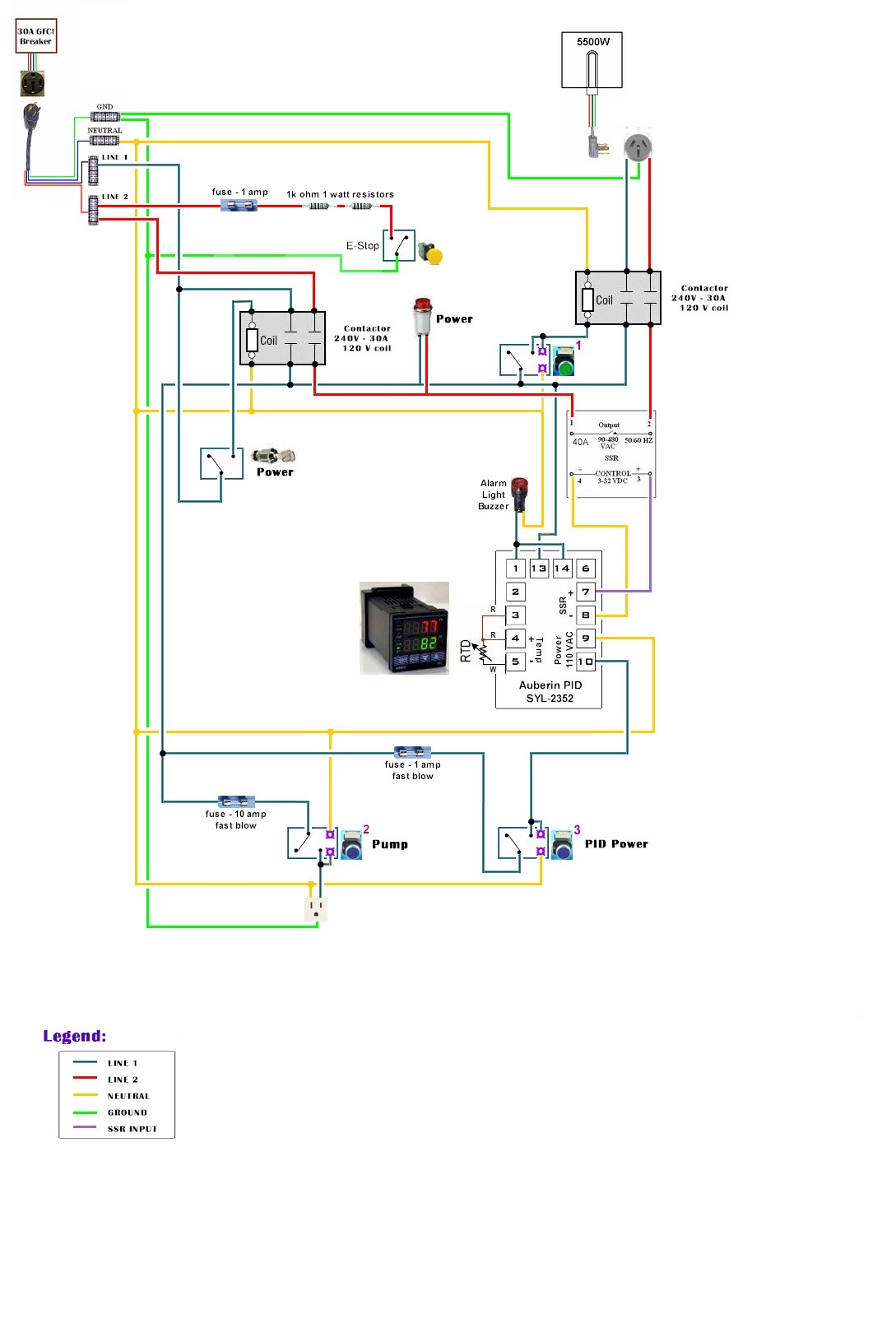
The following pics are my simple set up and one of P-Js wiring diagrams. Single 5500w element in the BK. There is no on/off switch with a key (ala Kal's) in the diagram and I would like to add one to turn the control panel on and off. Where in this diagram would I do that, please? Wanting a on/off switch (not keyed) for the pump as well.
Also, wanted to make sure the diagram I chose matches what I want to do with my set up.

Thanks!!

brewsetup.png


wiring diagram.jpg
 
To add a master keyed switch, you could add it inline with the blue/teal wire prior to the distribution block, this would prevent the PID from turning on, so the heating element could never turn on.

The diagram is already showing a switch for the pump, so that's covered, unless I am misunderstanding your question.

The diagram should work great for what you're looking to do, as long as you have the required 4 wire electrical service.
 
The push button switches shown, are they 2NO or 1 NO/1 NC. Are these preferred to a selector switch that is turned on/off or does it not matter?
 
So I started loading up my shopping cart with parts and while reading through Kal's set up I noticed that he:
1) does not have any resistors listed
2) he does have a 50amp shunt in his set up

From what I read it sounds like the shunt and resistors act similarly. Is this correct??
 
The resistors are PJ's method of tripping the GFCI breaker. Kal uses the shunt for his amp meter display.
 
Excuse my ignorance but your response intrigues me Brundog, you seem to have a deep conviction against PJs diagrams and the resistor method. Admittedly I don't fully comprehend the physics and engineering (or I would not need to post this forum to begin with) behind them, please indulge me as I like to get as much information as possible before making a decision.
 
I didn't get the whole resistor thing at first either but it makes perfect sense! it is a true E-stop because it interrupts the power circuit not the Control Circuit. Sure it would work if you put it in front of the coil but what happens if the Contacts weld themselves shut?!?!? Interrupting the coil power isn't gonna do S**t. Great drawing and great idea.
 
I didn't get the whole resistor thing at first either but it makes perfect sense! it is a true E-stop because it interrupts the power circuit not the Control Circuit. Sure it would work if you put it in front of the coil but what happens if the Contacts weld themselves shut?!?!? Interrupting the coil power isn't gonna do S**t. Great drawing and great idea.
This has been gone through MULTIPLE times, even though not ideal, it will trip the up-line GFCI and therefore stop supplying main power - so even if the contacts are welded shut, there won't be any power available
 
keep in mind this is for emergencies only. hopefully, it will never need to be used but if it needs to be, i don't see an inherent problem purposely introducing a current imbalance to operate the gfci. it is somewhat counter-intuitive, purposely introducing a hazard to achieve a safety function but it is workable and i am not aware of an obvious code violation setting it up this way. i suppose it could be argued that the gfci is not being used in accordance with its listing but i think it is still okay.

but even gfci devices are not automatic. they should be tested monthly to ensure they are still working. if you really want some belt and suspenders, get an e-stop button with a nc and no contact and install a main contactor. the nc contact will open to remove control power to the coil for the main contactor and the no contact will purposly create a current imbalance to operate the gfci. if the phase contacts are welded, hopefully the gfci will work or if the gfci fails, the contacts will open.

what's that meatloaf line, two out of three ain't bad?:eek:

I agree with this, I set mine up this way a few years ago and have had to hit the E-Stop only twice since then. I think that the NC contact opens a split second before the NO contact closes, so that the GFCI actually opens in an almost no-load condition. My normal stop button is a NC contact button wired in series with the NC contact in the E-Stop switch. I think that this is the best of available options.
 
Back
Top