Switching power between elements/PIDs possible?

Homebrew Talk - Beer, Wine, Mead, & Cider Brewing Discussion Forum

Help Support Homebrew Talk - Beer, Wine, Mead, & Cider Brewing Discussion Forum:

This site may earn a commission from merchant affiliate links, including eBay, Amazon, and others.

Rhino17

Well-Known Member
Joined
Jul 4, 2006
Messages
88
Reaction score
5
Location
Ontario, Canada
Hi All,

I am in the planning stages of converting my direct fire rig to an electric HERMS. Although I would love to run a 240v element in both my HLT and kettle at the same time, currently it's not an option.

My plan is 4500w 240v in boil kettle and 2500w 240v in HLT. I will heat my strike water in the BK, and then move to the HLT. Both elements will be controlled via PID and 40a SSRs. I would like to have a switch on my control panel that allows me to switch power between the 2 sides of my rig (from HLT to BK). This will allow me to operate on a 30a circuit. Later down the road, when my wiring is upgraded, I would be able to remove the switch, and power both sides at the same time.

Since the amp draw of the 4500w is 19a, could I use a 30a DPDT switch? Is a DPDT the correct way to go, or is there any other way to accomplish this?

Thanks,

Rhino
 
Both elements will be controlled via PID and 40a SSRs. I would like to have a switch on my control panel that allows me to switch power between the 2 sides of my rig (from HLT to BK). This will

The no cost option:
Put one of the temp controllers in the no run mode or off, depending on brand and model.

My edit.
Option two:
Install a 3-position selector switch between the PID out and the SSR.
Position 1, left = PID #1
Position 2, center = Both PID's
Position 3, right = PID #2
No high current selector switch required.


Cheers,
ClaudiusB
 
My control box has a dryer outlet and each of my elements has a dryer cord attached. When I want to use the HLT (the one that has the temp probe in it) I plug that in. When I'm done heating strike/sparge water I plug in the boil kettle and use the manual control.

I have a 30 amp switch on the box to turn off the current when I switch cords for extra safety.
 
Wait, if you never plan to have both energized at the same time, why would you waste the money on two controllers and SSRs? Operate a 3PDT switch on the elements themselves and the two temp probes. With one throw of the switch, all the associated electrics including the temp probes will be switched from the BK to the HLT.
 
Operate a 3PDT switch on the elements themselves and the two temp probes. With one throw of the switch, all the associated electrics including the temp probes will be switched from the BK to the HLT.

If he uses thermocouple probes the switch contacts should be made with thermocouple-grade calibration alloys.


Cheers,
ClaudiusB
 
If he uses thermocouple probes the switch contacts should be made with thermocouple-grade calibration alloys.

Cheers,
ClaudiusB

That is exactly correct.


Wow, they're really that sensitive huh.

Yes, they are. That is why I would shy away from using thermocouples if possible. They can be a real pain in the tush.
 
Yup, they are. Thermocouples are comprised of two different materials joined at one end and separated at the other. The separated ends are considered the output, and they generate voltage which is proportional to the heat they are measuring or monitoring. That is, the hotter the temperature, the higher the voltage. The fact that two metals generate voltage is known as the Seebeck effect. The voltage they generate is very small, usually milivolts. If you were to connect the output leads of the thermocouple to a switch, the switch would have to have contacts made of the same material as the thermocouple, otherwise the two dissimilar metals of the switch and the thermocouple leads would make another thermocouple and skew the output of your measurement thermocouple. PID's and thermometer are calibrated for specific thermocouples. If you were to intoduce another thermocouple by intoducing a switch of dissimilar metal the calibration of your PID or thermometer is comprimised. It's readings would not be accurate any longer. However, there is such a thing as a special thermocouple switch but they seem to be costly. I have seen a couple of thermocouple switches on Ebay for under $100 recently.
 
You don't need a probe in the boil kettle, though I suppose it would be nice. I didn't switch between two thermocouples because I did figure that putting a switch in line would screw up it reading the temp right.
 
So, Conpewter - You have a single PID+TC in the HLT, controlling a SSR, then when you switch to the boil, you just choose a different SSR (or plug for manual control) and set the PID to manual...?

I think that is doable. I know that the PID has to have the TC to have the circuit complete.
 
I only have one PID/TC and one SSR. I just switch between which element is plugged into to the control.

Yes I just use the PID on manual mode when doing the boil (100% to get to boil 50% or so to keep boil)
 
Yes, they are. That is why I would shy away from using thermocouples if possible. They can be a real pain in the tush.

As long we know how thermocouples behave we can design them into our system without problems.
My setup uses only thermocouples.

If you were to connect the output leads of the thermocouple to a switch, the switch would have to have contacts made of the same material as the thermocouple, otherwise the two dissimilar metals of the switch and the thermocouple leads would make another thermocouple and skew the output of your measurement thermocouple.

By using the correct material we try to minimize errors in tramnsmitting thermocouple signals due to thermal emf generated at the wire (switch) junction.

Cheers,
ClaudiusB
 
All your points are all very true.
In all due respect, I disagree, to a degree.
I have broken T/C's across terminal barriers and switches. As long as the resistance is the same across the two break points, the affect on the reading is minimal. Not to say that is no affect.

In what we are all doing here, does anyone do NIST traceable calibration to their equipment?
Do we believe that we can actually measure to a degree?
And that degree is the actual temperature?
Will that one degree make such a difference?
And do we believe we can really control to that degree?

Again, this is not to start an argument but questioned will all respect. I begin to think are we trying to catch a dragon.
If I were building a piece of equipment that needed to measure to the fraction of a degree then I would certainly take all necessary steps to ensure that my parts & practices were reflective.
I know we all strive for perfection but I doubt that all of our temperature displays in the same cup of water would all read the same.

To the OP:
I would use a SPST switch to energize 2 mechanical relays. One relay switches between 2 SSR’s and the other to switch between the 2 T/C’s.
Just my opinion.

Cheers
-David
 
I know we all strive for perfection but I doubt that all of our temperature displays in the same cup of water would all read the same.
The old saying:
The one who has only one thermometer knows what the temperature is, the one with many has no idea.


Happy brewing,
ClaudiusB
 
The old saying:
The one who has only one thermometer knows what the temperature is, the one with many has no idea.


Happy brewing,
ClaudiusB

Well said.
Cheers Claudius
-David

no no no no NO! This is where you two start to argue and fight. Then I step in with my brilliant wit and wisdom, settling the issue. Then we all hug and sing Kumbaya....
 
Thanks all for the help. I like conpewter's KISS design because it takes the least amount of equipment, but I think I would like to avoid having to unplug and replug depending on what element I want on.

David's suggestion seems the most attractive. It eliminates the need for multiple PIDs, just like compewter's design, but still incorporates a switch to transfer power. The only sticking point will be how much the thermocouple readings are affected by the switch. Since I already have 2 SSRs inbound from China, I think this is the route I am going to go. Worst case scenario, the temp readings are too skewed, so I remove the switch and wire in an outlet.

I'm going to start on my wiring diagram, but does anyone have a suggestion/link for a suitable mechanical relay?

Thanks again!

Rhino
 
Since the PID on boil is used on a manual mode, the tc is only needed to complete the circuit (the value is not used). So, why use 2 TC ( other than to monitor the temp while chilling) via a relay ? Seems to add a layer of complexity.
PIDControl.jpg
 
Rhino,
Which controller & sensor are we talking here?

Irr, you have a good point. Rhino may want one there for data collection or so he doesn't have to change the controller settings at each switch.
 
Since the PID on boil is used on a manual mode, the tc is only needed to complete the circuit (the value is not used). So, why use 2 TC ( other than to monitor the temp while chilling) via a relay ? Seems to add a layer of complexity.
PIDControl.jpg

This is a good design as well but does need two SSRs. It would be nice to just switch the 220V after the SSR but it can be hard to find the proper switch; one that has 3 position On/Off/On and can handle 30 amps at 220V. I think Kal was looking in to this option in his threads about his electric build.
 
Yeah, I think you'll find the additional SSR to cost less than the 3PDT 30a switch..
I'll be doing this style this weekend (PID on the way, everything else is ready). Yeah, I already had two 40a SSR's :)
 
Rhino,
Another option is a highbred between the two basic ideas.
A DPST switch to change between SSR's and an actual Thermocouple Jack to manually connect the proper sensor.
This would keep the wiring path pure the thermocouple. But, it does run the risk of forgetting to change to the right T/C and then the element would run away.
Jacks & Plugs are relativly cheap. (Pyromation.com)

I don't think we actually determined what type of sensor you will be using. If it is say the sensor that comes with a Love Controller then this is a thermistor and all this thermocouple talk is mute.
 
Yeah, I think you'll find the additional SSR to cost less than the 3PDT 30a switch..
I'll be doing this style this weekend (PID on the way, everything else is ready). Yeah, I already had two 40a SSR's :)

Things brings up a good point. Make sure to get a 40a SSR. Even though your elements could theoretically work on a 25a SSR you want the larger one since it will last longer and not get as hot.
 
I was thinking I would order the same PID that The Pol is using:

PID Temperature Controllers : auberins.com, Temperature control solutions for home and industry

with this thermocouple for the BK

K Type Thermocouple (6 ft. cable) English thread [TC-K6]

and this one for the HLT

Liquid tight K type, 4” probe, NPT Thread [TC-K100MMNPT]

My assumption is that the shorter thermocouple will not be very effective for the HLT, but the 4" will allow for a more accurate reading of the water temperature near the HERMs coils, or I could put it at the out-flow of the HERMS to measure the wort temperature.
 
That is basically what I have.
One thing, on the HLT, if yours is cooler based (like Pol's & mine) that threading won't do you much good.

Based on that, and advice from Aubern, I went with the Platinum RTD. PT100 (6 ft. cable) [PT100S] - $15.65 : auberins.com, Temperature control solutions for home and industry , that will push through a drilled rubber stopper. I have tested that with another probe and not had any leakage. A little keg lube takes care of any minor leaks.

I ordered the connectors (2) as well, so I can extend to a 2-probe in the future..
 
OK, so you are indeed looking at K T/C's.
The resolution of that controller is 1 degree with a T/C.
I would expect about 1 to 1.5 degree shift if wiring through a switch but, YMMV.
If you can live with that then go for it. If you can’t then either go with manually changing the T/C's or switch to the PT100 RTDs and use the relay scenario.
-Just my opinion
Cheers
-David
 
I am having a problem locating a decent source for 240v switches in Canada.
However, I can get illuminated 12v switches from Princess Auto for $3 each.

So, could I use a step-down transformer to to get to 12v, and then use 12v switches to control 4 or 5 ssr? Any problems you can see going this route? Would there be a specific type of step-down transformer I would be looking for?

I think I would need 5 SSRs to do the following:

12v - 40a SSR - 4500w ULD BK element
12v - 40a SSR - 2500w ULD HLT element
12v - 25a SSR - 1650w HEX element
12v - 25a SSR - March Pump
12v - 25a SSR - Stir Motor

Would this work? Also, 25a is overkill on the pump and motor, but it is the smallest AC SSR that auberins sells. I know that automationdirect sells 15a SSRs, but they are DIN rail mount. I was going to put everything in a mdf box. Would heat be an issue with the 15a SSRs in a mdf box? Can you buy stand alone DIN rails to make mounting easier?

I guess I just need some helpful direction right now. I know once I settle on the components, the wiring will go pretty easy. But right now i have 2 40a ssrs, 2 elements, 2 pids, 2 thermocouples and a 16"x16"x7" mdf box sitting in the corner taunting me!

Cheers,

Rhino
 
I have a "Spa Panel", which is a 50A GFCI Circuit breaker that I use for my Main Power.


Then I take the output of the SSR's and run it through DPDT switches like these. This allows me to cut the electric (both poles) to the device.


Also a great idea vs just breaking only one leg to the element that some members have posted, elements cold but still energized, it's all about safety.

The "Spa Panel" has always been my cheap and safe way to go as my company always had spares that I brought home.

Years ago with a indoor / outdoor TC with switched leads that was in a damp location they were always acting up. I ended up using two old glass tube mercury switches. The resistance of these switches were trouble free and would repeat the same switched readings still working the past 30 years.
 
I have a "Spa Panel", which is a 50A GFCI Circuit breaker that I use for my Main Power.
Then I take the output of the SSR's and run it through DPDT switches like these. This allows me to cut the electric (both poles) to the device.

+2 on this... I cut both legs to the element too... it is easy to do, so why not?

Larry... you brewing on that beast this weekend?

I wanted to go to the BIG BREW DAY up here, but they dont have a 240VAC circuit that I can use.
 
Yes, I brewed on The Beast yesterday.

Long story short, lessons learned:
1. Come up with some way of monitoring the level of water above the element. Event just the tip getting dry will cause meltdown (literally).

2. Buy a spare 40a SSR. My boil SSR would never shut off. This is the 2nd from Auber that I've had a problem with. The first was bad out of the box.

3. Don't use a 4500w element in the HLT. You don't have enough time to grind grain and pour a homebrew before mashing in :) See #1 for down sides.

4. Get some of those damn HDPE containers and skip the CFC, increasing the efficiency into the ferm, decreasing my PITA factor.

My brew was a BeeCave (EdWort) Haus Ale. I overshot the OG by 6 points (1.060) due to an 82.8% efficiency! This tasted YUMMMMY on the sample.
 
Yes, I brewed on The Beast yesterday.

Long story short, lessons learned:
1. Come up with some way of monitoring the level of water above the element. Event just the tip getting dry will cause meltdown (literally). You need THE POLs $3.28 Sight Gauge!

2. Buy a spare 40a SSR. My boil SSR would never shut off. This is the 2nd from Auber that I've had a problem with. The first was bad out of the box. Are you serious?? Of course you are... how many sessions before failure?

3. Don't use a 4500w element in the HLT. You don't have enough time to grind grain and pour a homebrew before mashing in :) See #1 for down sides. OUCH

4. Get some of those damn HDPE containers and skip the CFC, increasing the efficiency into the ferm, decreasing my PITA factor. $13 at USPlastics.com!

My brew was a BeeCave (EdWort) Haus Ale. I overshot the OG by 6 points (1.060) due to an 82.8% efficiency! This tasted YUMMMMY on the sample. EXCELLENT!!


Live and learn!!
 
If you use PID then your HLT can be ready for mash when you need it. You can set a timer to turn on the PID controller the next morning and it will be ready. If the element is too big then just use 40 or 50% on the PID and it will slow the heating. Having a water level maintained could be as simple as a float valve.
 
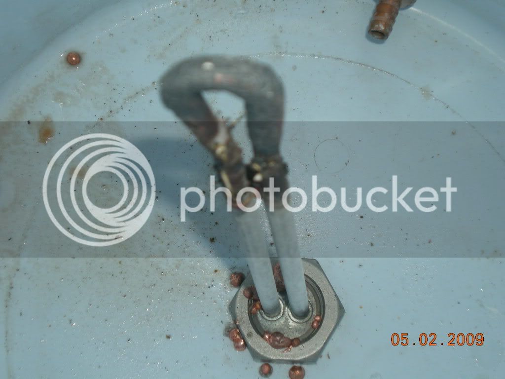
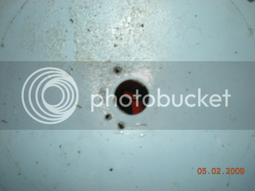
Ok, here is what happens when you aren't paying attention. This was done using a 4500w element during fly sparging. V2.0 will have a level switch to prevent this.

DSCN0254.jpg


Note the little balls of copper that produce this:
DSCN0256.jpg
.

Looks like a trip to Home Depot.
 
I admit, when I fly sparge, I turn my HLT OFF. I figure, it is 173F already, the grain bed is 166-168F and it is a cooler, so I shut mine off so that I dont accidentally do that.
 
I was at Menards (home depot like store) and saw the 4500W ultra low density elements (less than 50W per sq inch) that were straight. I think the 5500W ULD elements have to be rippled to have enough square inches. The 4500W ones were bent back on themselves, and black like the other ULD elements.

The Pol. I also unplug my HLT when I start sparging. I don't want to dry fire if I can help it. Also if it is a 10 gal recipe I'll sometimes have enough wort that I can start the boil with the first runnings and then pump in the two batch sparges as I get them. If not I can always start the boil after the 1st batch sparge.

Found one
https://www.hardwareworld.com/4500-watt-Lime-Life-Element-pN7NU1T.aspx
 
Thanks compewter, that is the element that I went with, picked up at Home Depot today.

Now waiting on the new SSR and to pick up a new cooler. The old one, I will patch the bottom with a piece of plexi and make that a grain storage unit.
 
Back
Top