Single Tier Brew Stand with BCS460 Complete Build

Homebrew Talk - Beer, Wine, Mead, & Cider Brewing Discussion Forum

Help Support Homebrew Talk - Beer, Wine, Mead, & Cider Brewing Discussion Forum:

This site may earn a commission from merchant affiliate links, including eBay, Amazon, and others.

Cardog

Well-Known Member
Joined
Mar 1, 2010
Messages
89
Reaction score
24
Location
San Diego
First, I wanted to thank everyone on this forum for their contributions to HBT. I have literally learned 90% of what I know about brewing and putting this brew stand together from this forum. So, as a “thank you” …it’s my turn to give back to the community by posting my build thread.

I am here to share advice and answer all of your questions. So this is not just to show off my rig. I am truly trying to give back here.

This brew stand is already completed and documented with pictures but I will be sharing the process a little at a time so I can share every step in detail and answer questions along the way.

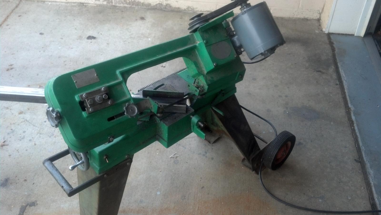
And it starts off just like this:

IMG_20130406_190808_095.jpg
 
Time to get to work. Having a band saw makes the cuts extremely accurate and as you can see, I can cut just a sliver if I need to make an adjustment.

IMG_20130407_155551_918.jpg

036.jpg
 

Attachments

  • IMG_20130407_151159_277.jpg
    IMG_20130407_151159_277.jpg
    131.2 KB · Views: 625
Since I had drawn the brew stand with Sketchup, I was able to cut every single piece before welding. Although it is not the most efficient way to work, I wasn't racing against the clock like some other paid projects I do. When you do it this way, you have to cut everything a 1/16"-3/32" shorter than your actual dimension. This will assure everything will fit like a glove the first time without having to go back and trim pieces.

So therefore I can show you this:

IMG_20130411_114650_571.jpg
 
Because of the size of the brew stand and the huge angle clamps, I had to weld the first part in 2 steps.

IMG_20130411_121227_810.jpg

IMG_20130411_123759_411.jpg

Mad welding skills that unfortunately get grounded down (expect for the inside corner) to perfection to look like one piece!

IMG_20130411_124332_842.jpg

IMG_20130411_125824_690.jpg
 
You will find throughout the build that I spared no expense on this project and have designed this as an extremely "clean" build. Starting with a custom gas manifold that will be integrated into the frame.

3 holes were drilled and 1/2" couplers were welded in place. I welded end caps (towards the inside of the square tubing) plugged the couplers then pressure tested with about 20 psi of air. This would be more than enough as natural gas runs well under a pound.

015.jpg

016.jpg
 
As part of keeping the design clean, I have elected not to do manual switches and rely solely on the BCS460 interface. You will also see that everything was designed and engineered to have all the wires run through the inside of the frame.

As you can see, I have drilled large 1 1/4" holes to accommodate this feat. I have more photos that will elaborate on this later.

020.jpg

021.jpg


Here is the pump mount and as you can see there are 2 holes: 1 for the pump power wire and 1 for the temperature sensor.

Pump Mount.jpg


These are all the pieces that make up the design to run the wiring through the frame.

022.jpg


Here I tack welded some washers at a 45* angle (to keep a low profile) to the gas manifold in order to secure the wiring for the gas valves.

Manifold.jpg

manifold closeup.jpg
 
Ok, so now I welded the gas manifold in place. In the second pic, you'll notice the 1 1/4" holes in which the wiring will feed through.

Clamping the Manifold.jpg

Front View Manifold.jpg


I will be using aluminum diamond plate for some nice trim work. This shows the 3/4" square tubing welded in place specifically to mount the diamond plate. It will be a tedious job but I will have to drill and tap into the 3/4" tubing to bolt the diamond plate in using stainless steel cap screws.

Rear trim plate mount.jpg


More work done on the stand.......

Full Front.jpg
 
And now for the kettle seats.

I cut out a piece of wood for the exact inside dimension for the kettle seats to use a jig and clamped all 8 pieces to tack weld in place.


Seat Jigged.jpg

Seat Tacked.jpg


So basically I used the first one I made as a jig for the next 2.

seat2 jigged.jpg


Then it was tacked in place.....

Seat2 tacked.jpg


Then welded.....

seat2 welded.jpg


And there you have it!

finished seats.jpg
 
So obviously these kettle seats are going to get extremely hot with direct flames. So after much research I have decided to use VHT flame proof paint. With this particular product it's all about the curing process. I taped off the ends so I have bare metal still exposed to be able to weld the seats in place.

The curing process calls for 15 min at 200*F then cool for 30 min, then another 15 min at 400*F and again cool for 30 min, and last....15 min at 600*F. So how the hell was I supposed to do that??!! Well, below is a picture that tells a 1000 words. Just don't tell my SWMBO what I did that morning while she was at work :D

paint.jpg

018.jpg


Notice the bare metal how it blued from the heat in the oven

after cured.jpg

after curing.jpg


After all said and done I was able to get it clamped up.......

clamped seats.jpg


........ and welded in place

welded seats.jpg
 
Ok, it's time to build the frame for the box in which the electronics will be housed in. The square tubing here is 1/2"


box frame.jpg

box clamped.jpg

box frame welded.jpg


The other thing I wanted to point in these pics is the framing for the floor where the diamond plate will sit on. It sits about 1/8" below the 1 1/2" main frame. So when the 1/16" thick diamond plate is installed it will be recessed about 1/16". It will be basically be silicone glued in which will seal it from the fluid spills leaking in the box.


box set in.jpg

box set in 2.jpg

box set in 3.jpg


Now that the clamps are out of the way, here is a better look.


box frame pic.jpg

box frame pic2.jpg
 
When BrunDog said it was like binge watching.....It's because the entire build is completed and I actually have several brews on it already. So if you want to hit me up when you are in town, I would be happy to share.
 
These pics will show the design to allow the wiring to go through the frame and down into the electric enclosure. The 2 large holes that are close together will be covered with a triangular piece (you'll notice that in the final pics). And if you are wondering why I just didn't drill through frame piece that goes across......well, that's the gas manifold.

Like I said, it is a simple clean design. There is only 3 sets of wires: temperature sensors, gas valves and the pumps that's it!

frame1.jpg

frame2.jpg


Here you have a close up on where the gas valve wiring goes through.

gas valve hole.jpg


This is the right behind the mount for the pumps where you see the holes for the temperature sensor and the power wire for the pump runs through.


pump holes.jpg
 
Now for some peripherals. The brackets shown are for the wort chiller and the water filter.


CF chiller.jpg

CF chiller back.jpg

water filter bracket.jpg
 
Looks like you put a lot of careful thought into the planning. Awesome welds and craftsmanship, can't wait to see the rest!
 
Yup, once you know what kind of process you want to do and a vision for all the other stuff....it's software like Sketchup that makes it a lot easier to plan and do.

Anyways that pretty much does it for the welding of the brew stand. Now we will get into the fun stuff with the paint, assembly, wiring and finished pictures. Just give me another 2 days or so and I should have the build thread completed for you guys.
 
Wow, looks like you got mad fabricating skills as well! Looking awesome, keep the pics coming, loving this thread!

John
 
Now that it is all welded up, it's time to prime. This was primed with a 2K epoxy primer.

IMG_20131006_165307_053.jpg

IMG_20131006_165344_212.jpg

IMG_20131006_165426_646.jpg

IMG_20131006_165532_937.jpg

IMG_20131006_165621_344.jpg


And for the paint...... I painted this with an acrylic urethane automotive paint. Although you don't really see in the pic, it is a metallic paint.


IMG_20131016_163926_123.jpg

IMG_20131022_174029_336.jpg
 
You guys are probably wondering what the dead space is on the bottom of the stand. Well......it's for a drawer for all my gear!


IMG_20130930_174220_244.jpg

IMG_20131002_160616_910.jpg


Had to weld a piece of flat bar so I can mount the drawer slides.


drawer slide frame.jpg

drawer slide.jpg
 
Ok, so now we move on to the electrical enclosure. The enclosure is made from 16 ga. aluminum sheet.


box parts.jpg


How do you cut the aluminum you ask? There's a tool for that!


saw blade.jpg

table saw.jpg


And how it looks assembled.

box assembled.jpg

box assembled 2.jpg
 
I know what you guys are thinking.........what the hell is inside the enclosure. Well not much really. Because of my clean design with no manual switches, all we have really is just 5 relays and 1 transformer. 2 relays control the pumps and the other 3 relays control the gas valves. Yes that's right I have a gas valve for the boil kettle. The transformer is the step down to24V for the gas valves.


relay board.jpg


Since the BCS460 is located permanently in the garage next to the fermenter everything is connected by Cat5 cables. The other plug you see is the 120V power.


Diamond plate.jpg

diamond plat cat5.jpg

cat5 close up.jpg

inside box.jpg

inside box close up.jpg


If you click for a close up, you can see the stainless steel caps crews. I chose these purely for aesthetics.

cat5 finished.jpg
 
Now you can see how the wires get routed.


wirng1.jpg

wiring2.jpg


I have a temperature sensor for the wort chiller on the side of the stand.


wiring for temp.jpg

wiring temp2.jpg


Here is how the gas valve wires go through.


wiring gas.jpg
 
Your eye for detail here is really impressive. Couple questions for ya:

I'm guessing you weld professionally, or at least as a result of your profession since it takes some serious confidence (read: cajones) to fabricate a gas manifold yourself. I also saw the soap test pic. How'd the soap test go? Did you pressure test it? What were the considerations or details while building this particular part of your frame since it can obviously (at least to me) hold a fair amount of gas when comparing to a standard pipe-based manifold?

Also, just out of plain curiosity: I know you've already built this and tested/brewed on it, and weren't in a hurry. How long did the build take you? How'd your first brew go? Did you hear angels singing?
 
I am not a welder by trade but my experience was a result of my profession (which I don't do anymore) and I am self taught. After reading other threads about creating a gas manifold it was interesting to know that most people wouldn't take on the task. Personally I didn't think it was that big of a deal. Turned out it wasn't an easy task. You do have to have some good experience in welding. I used 14 ga. tubing throughout which I felt it was sufficient for welding the manifold. I could of have use 16 ga. for the brew stand but 14 ga. is much easier to weld with and would never use 16 ga. to begin with for the manifold. This would have been way too difficult to weld the couplers on with the different thickness' of the couplers and 16 ga.

So they way I did it was first to bevel the couplers where I was going to weld. This was tricky since it was round. So what I did was put a reducer bushing in the coupler to a 1/4" then connected a 1/4" nipple like 2" long and chucked that puppy into my drill press. Spun it on the drill press at the same time I use my grinder to make the bevel. Worked beautifully as I make a perfect bevel.

The next step was to cut some flat stock that fit inside the tubing for the ends. This had to be recessed inside so it wouldn't interfere with welding the manifold on the stand. So in other words don't weld a cap on the outside end of the tubing. Because once you weld that to the stand then you are essentially weld on top of your welds that you got perfect to seal it. It will distort the original weld and may cause a pinhole leak.

After that you plug up 2 of the couplers and put an air fitting on the other to hook up your hose to pressure test it. A little soap and water and you can see if you have a leak. Here's where the welding get tricky. I didn't have a perfect seal as I had multiple pinholes. So I had to grind the weld where the pinhole was and rewelded it. More of small grind and a tack weld as to not to disrupt the rest of the bead that sealed. I say tricky because I ended up doing this about 7 times before everything held 20 psi.

This build took about 2 1/2 months in my free time and it worked right the first time if you can believe that!! After multiple dry runs with water mostly testing the programming for the BCS460 the first brew worked flawless. I get consistently between 80-82% efficiency. So yes, the angels were singing. :rockin:
 
Now you'll see where the Cat5 cables plug into..........

Cat5 Plugs.jpg

Full view.jpg


Inside the panel is the BCS460, 1 relay (for the fermenter), a Netgear wireless adapter (WNCE2001) and a shallow surface mount power outlet.

I made sure that I didn't have any interference with the signal cables and the power cables so I ran 2 separate conduits instead of one larger one. This insured that my temperature sensors will work accurately and they do!


electical panel.jpg

Inside panel.jpg
 
If you noticed in the last set of pics, there is a black plug on the left side. This is where the temperature sensor is plugged into from the fermenter.

plug for temp.jpg

temp plug.jpg

fermenting wort.jpg

freezers.jpg
 
Just give me an extra day or 2 and I will have the finished pics posted......stay tuned.
 
Extremely well thought out design and functionability. This is right up there with some of the best of the best on this site. Gotta love the red paint too!

John
 
I made sure that I didn't have any interference with the signal cables and the power cables so I ran 2 separate conduits instead of one larger one. This insured that my temperature sensors will work accurately and they do!


View attachment 344812


I've been told that code here in San Diego anyway is that when using conduits you should only run individual wires and not romex - something about the added insulation in the small volume can lead to heat issues. It may be different where you live. Those runs are pretty short and prob not very high loads so you may be fine. But I thought I'd share what I've learned during my house wiring endeavors.

AMAZING build - and I love the drawer idea - it's in my plans for when I (someday) build a stand.

What do you think it weighs?!
 
You are definitely probably right about the code but from everything I read there seems to be an acceptable gray area there. Nice catch on that.

As for the weight (this probably within a 10 lb ball park) the stand itself is about 130 lbs. Add the peripherals (burners, valves, drawer, wheels, etc) and you are looking at right around 235 lbs.
 
Back
Top