Well after much thought I have decided to start an official build thread. I started my rig build about two years ago, and have not made much progress untill recently. I have been documenting my recent progress on my help thread and have seen no feedback in the past few weeks so i decided to start a new thread, more appropriately titled, to document my build and share my methods.
Just to bring you all up to date, my original plan was a single tier, steam infused mash setup powered by a pressure cooker that I modified for steam bending wood. Including a tippie dump, two pumps, hard pipe plumbing,and 100 percent manual. I like the human aspect of brewing.
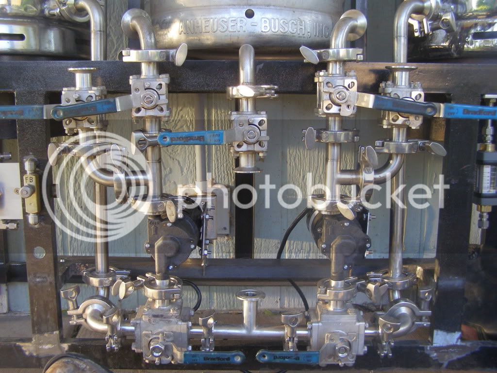
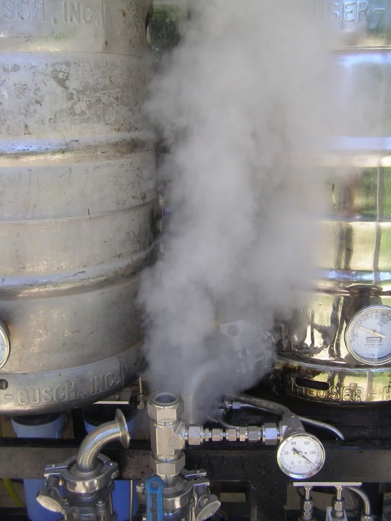
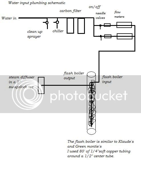
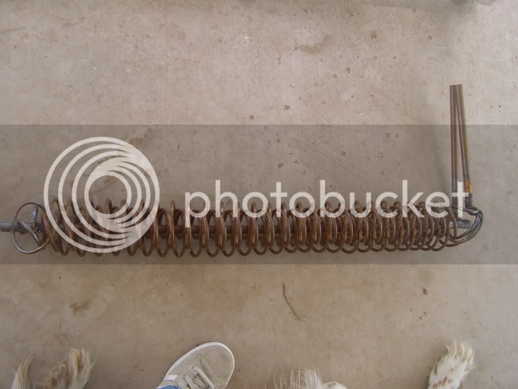
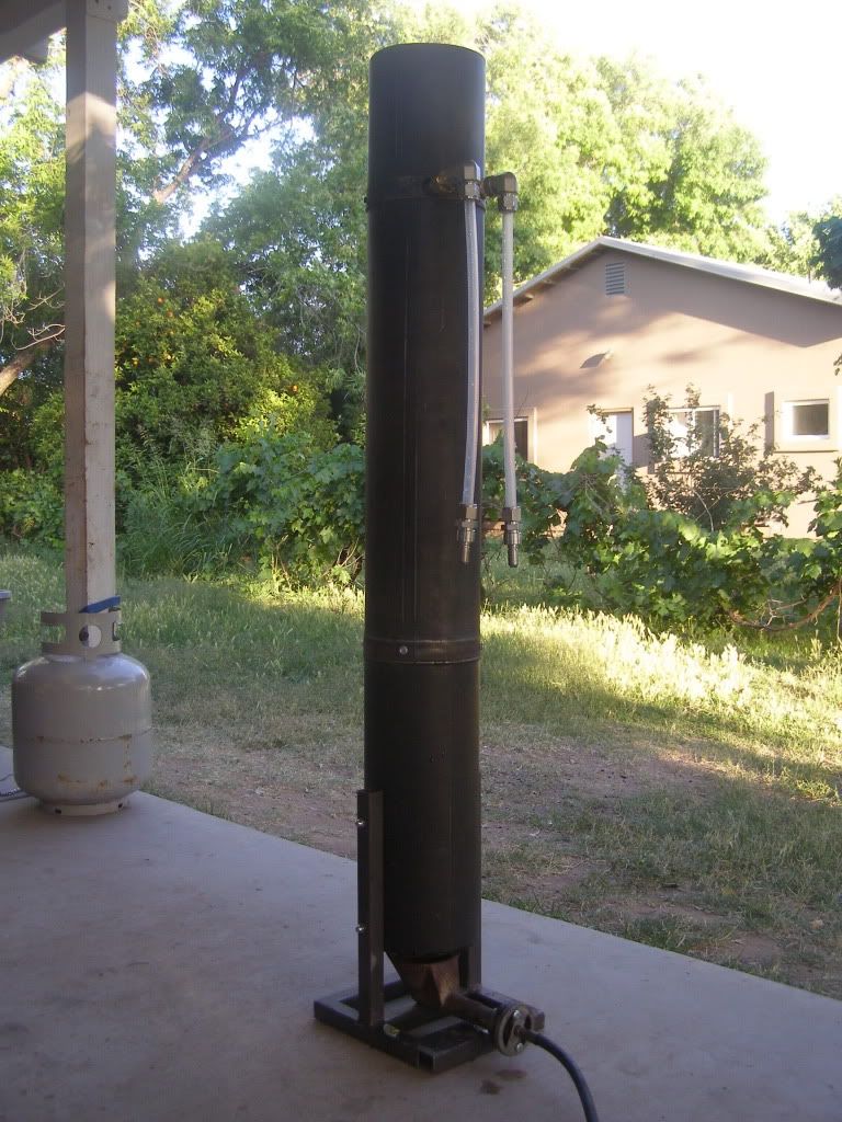
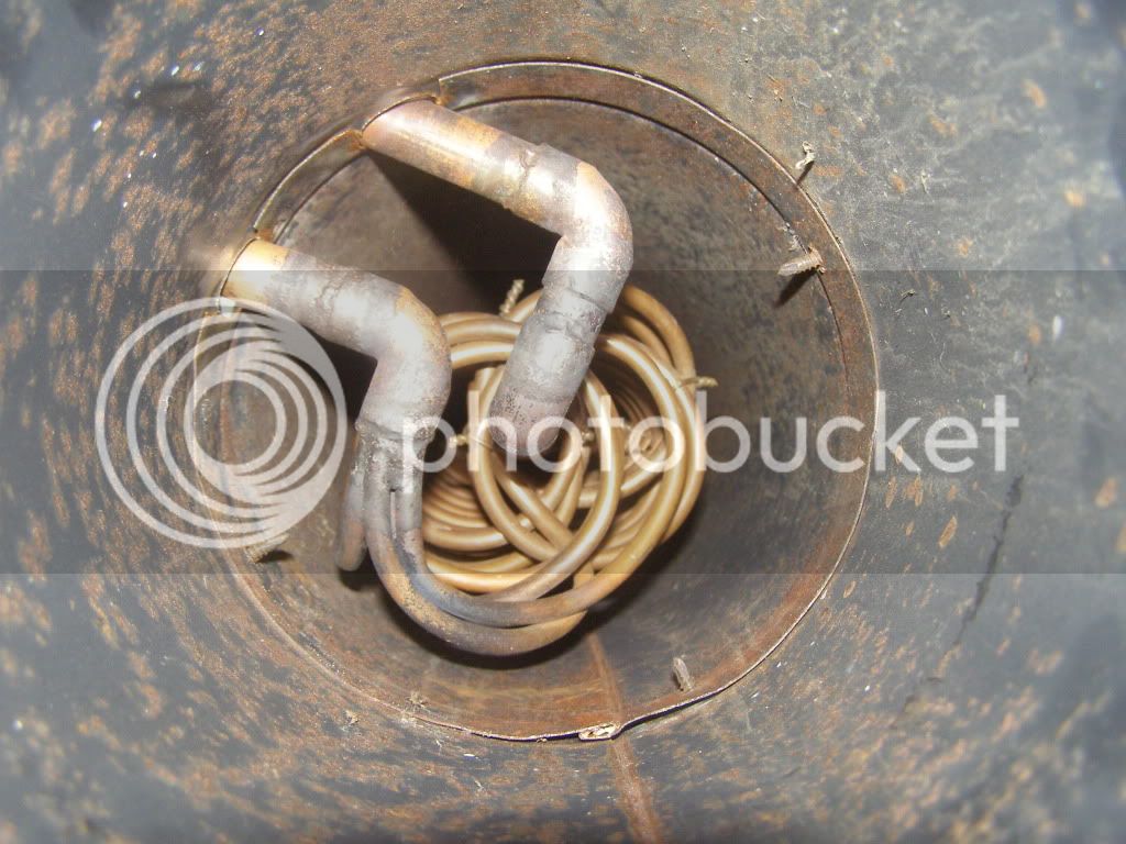
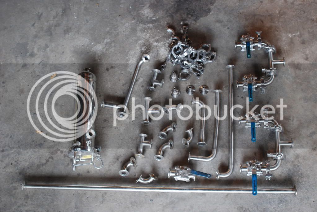
I have made a few changes to the original plan mainly the pressure cooker idea has been replaced by a Flash Boiler simillar to Klaude's and Green Montie's. Mine is four 20' lengths of 1/4" soft copper tubing. Also I scored a bunch of Tri Clover fittings, valves etc. at the local scrap yard for 88 cents per pound!!! I bought about 400 lbs worth and sold off the stuff I didn't need to recoup my investment. With a heaping pile of Tri Clover pipe and fittings i began to piece together my plumbing.
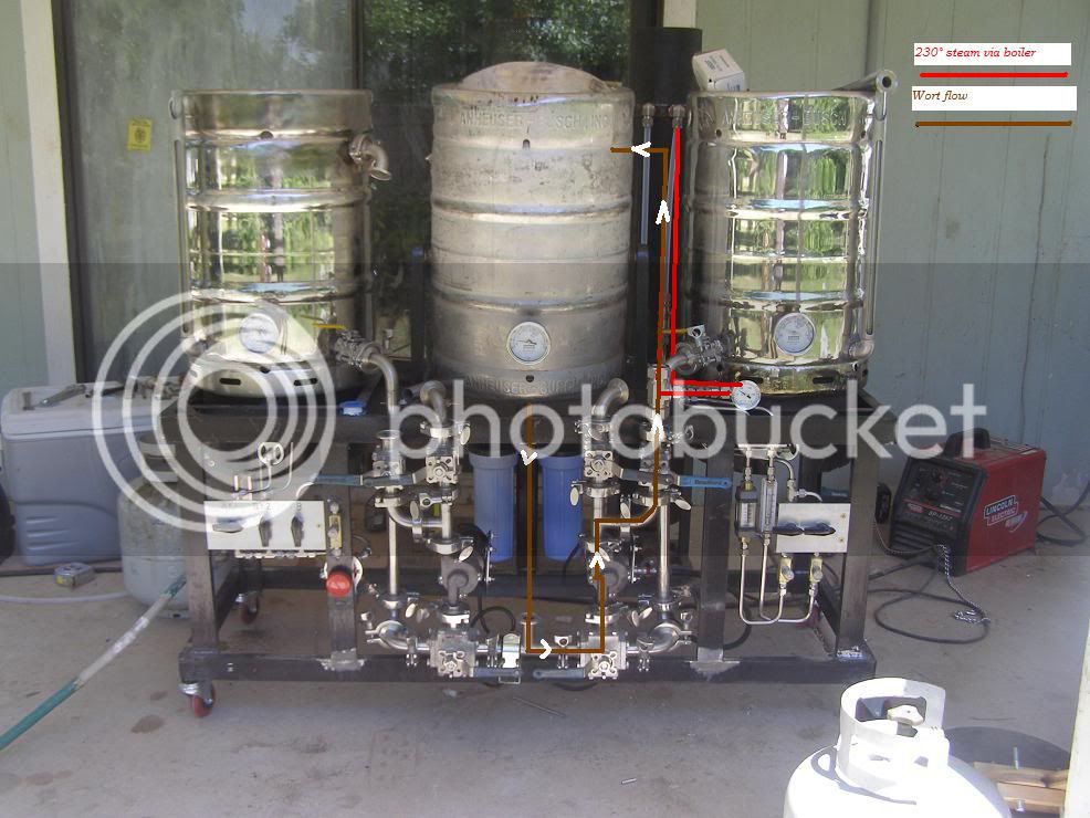
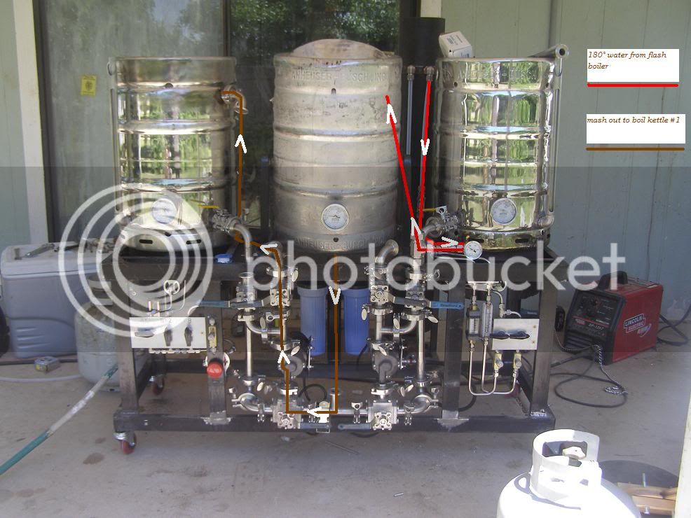
My main justification for starting this new thread is that I have not seen any body hard pipe a rig with Tri Clovers. Also I think my rig very visualy shows the wort flow path and I think this might help people thinking of doing somthing similar. Also the manual flash boiler settup is fairly simple without all the electronic gagetry to confuse the actuall prosess. over the next couple of weeks I will post up pictures and methods. If you have any questions or comments, speek up and I will do my best to answer all. I want to document this build as detailed as posible, and doing it sort of after the fact I might leave somthing out.
P.S. The computer is a tool I am not very good with, so bear with me keeping up with my slow fingers.
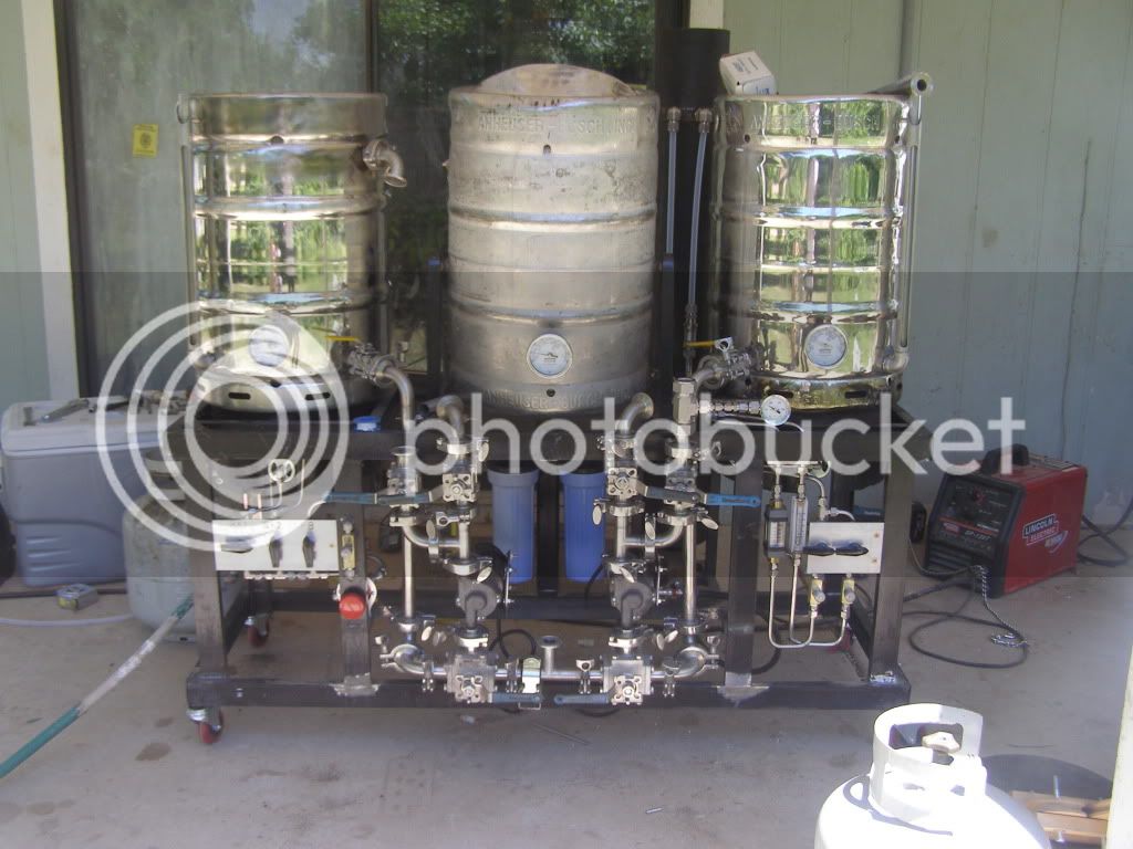
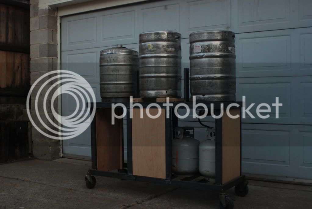
Here is the original stand configuration. I got rid of the wood panels, one caught fire while testing the burner. I also had to move the center uprights closer to the outside to accommidate the Tri clover plumbing. The stand was welded with an old rusty stick welder that I found in a ditch at one of my brothers investment propertys. The keggle on the left was the 1st one i built I welded the band around the top with alumnum wire, I thaught kegs were aluminum. I still brewed a few batches on it!!!
Some of the Tri Clover stuff from the scrap yard.
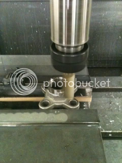
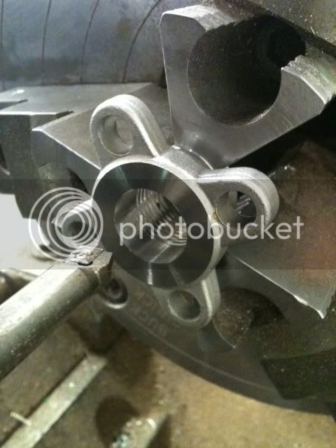
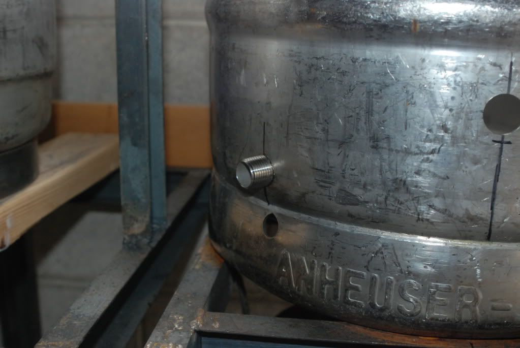
Drilling kegs for valves.
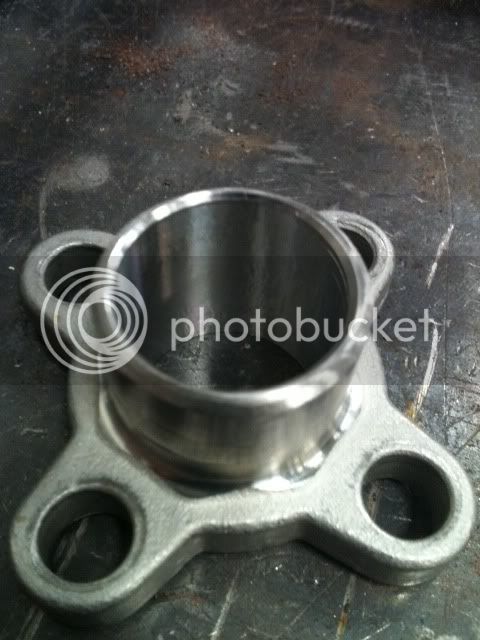
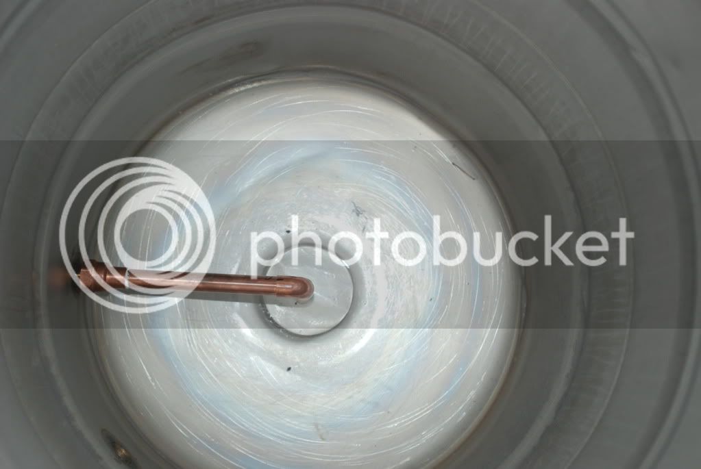
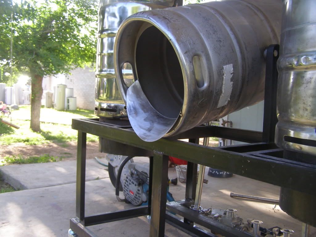
The inside of my one usable keggle.
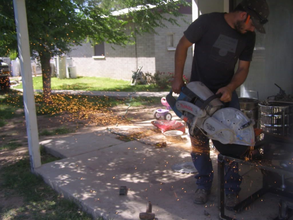
Here I am cutting the stand down for the seconed time. This saw is sweet I have used it to cut cars into movable pieces in the past.
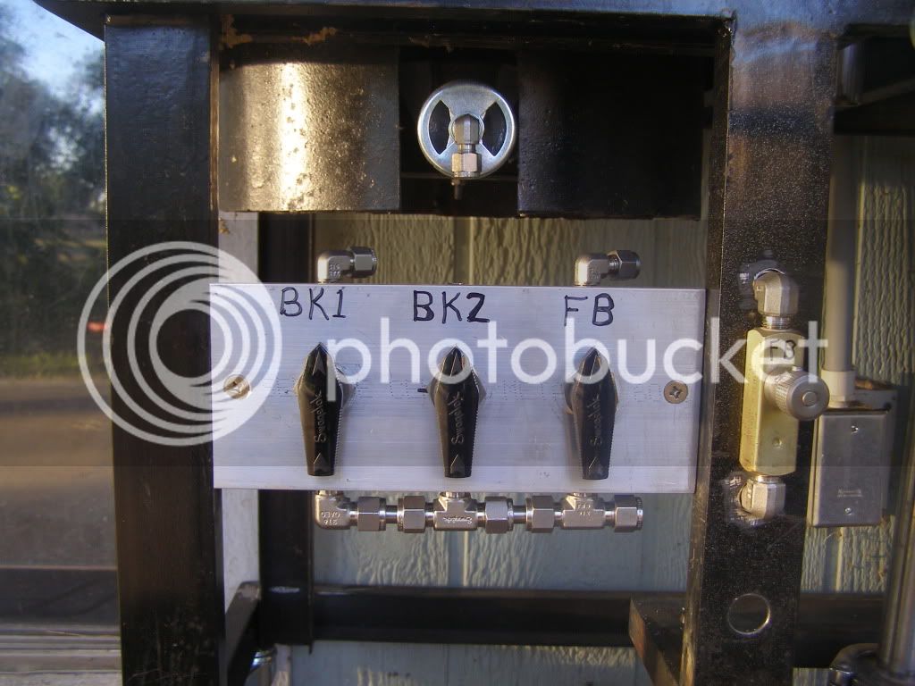
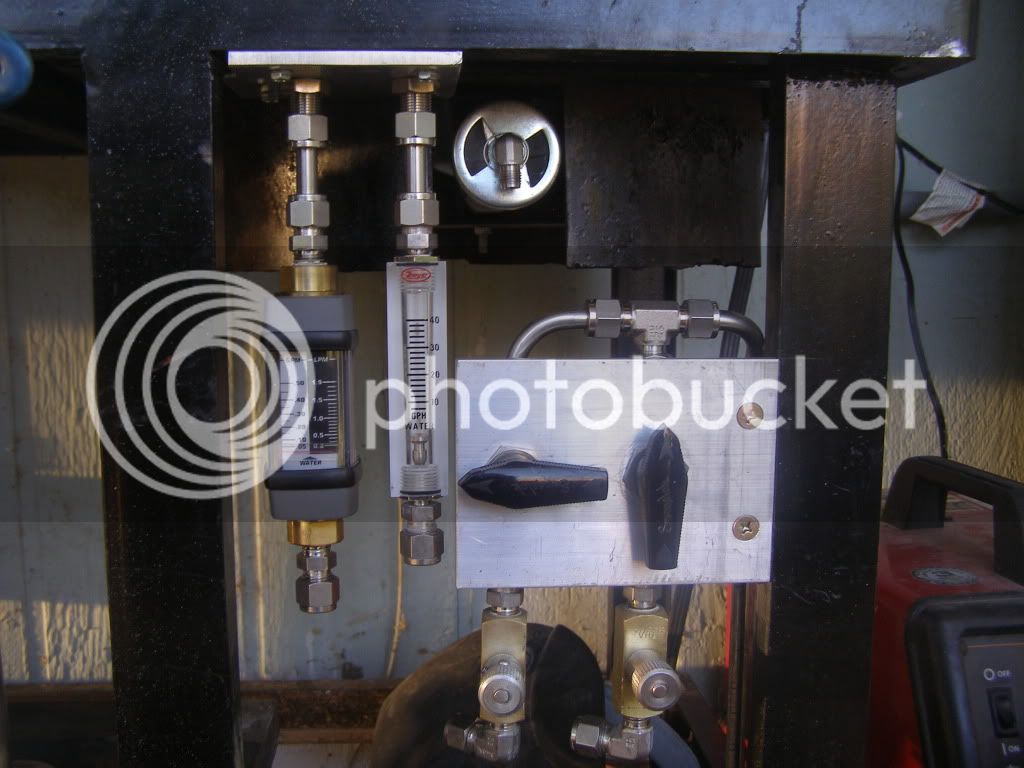
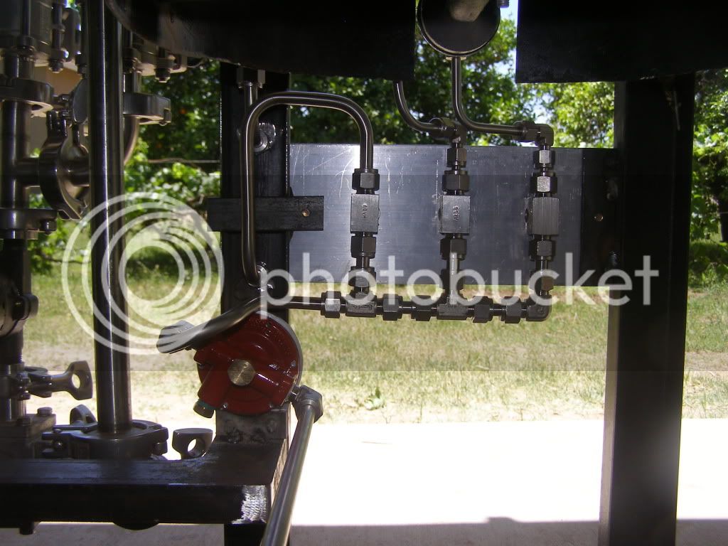
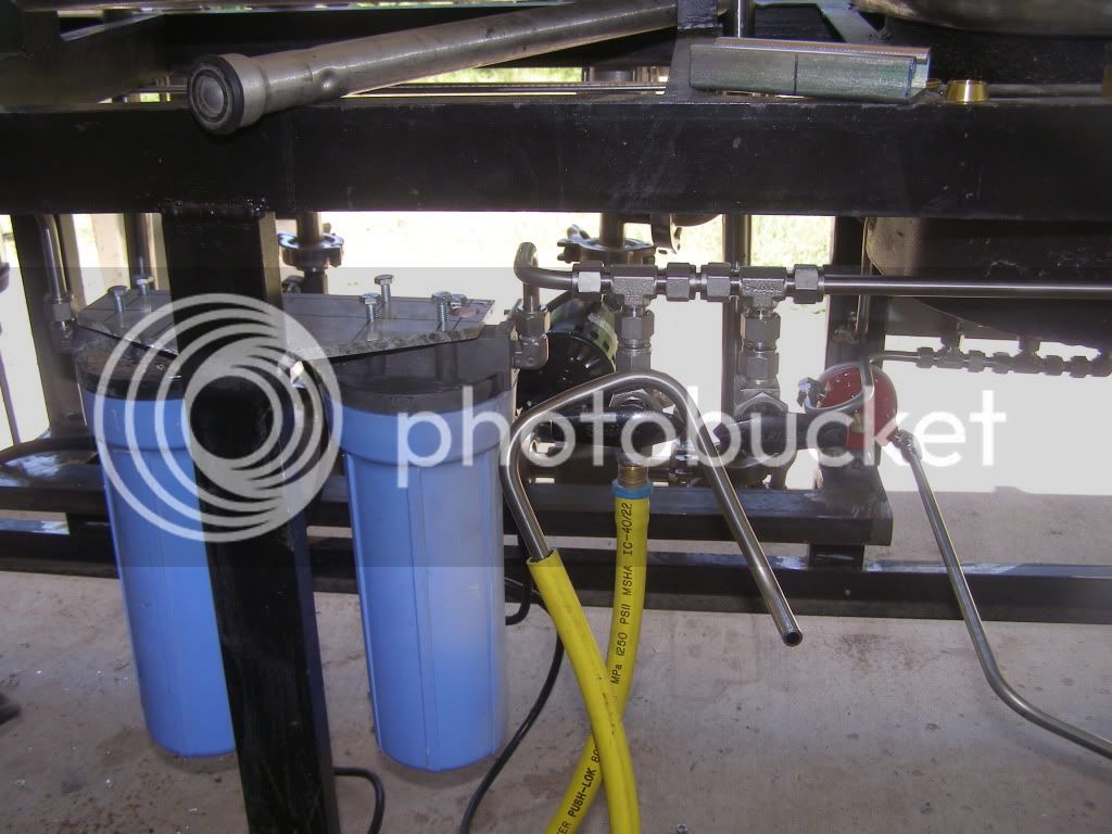
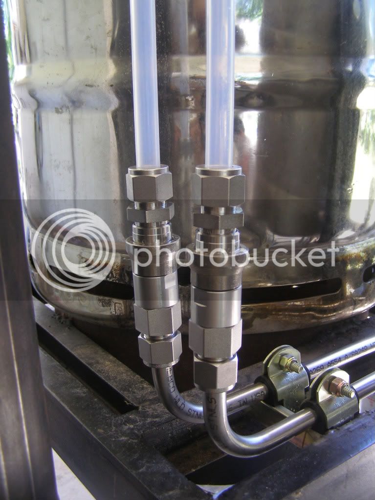
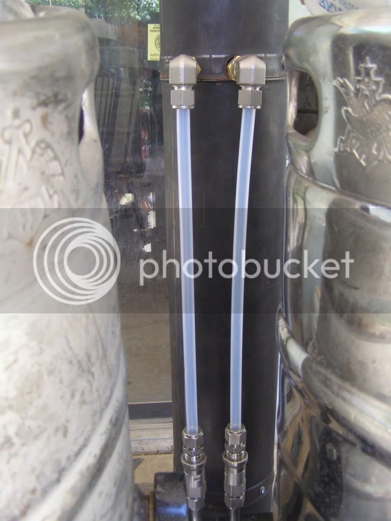
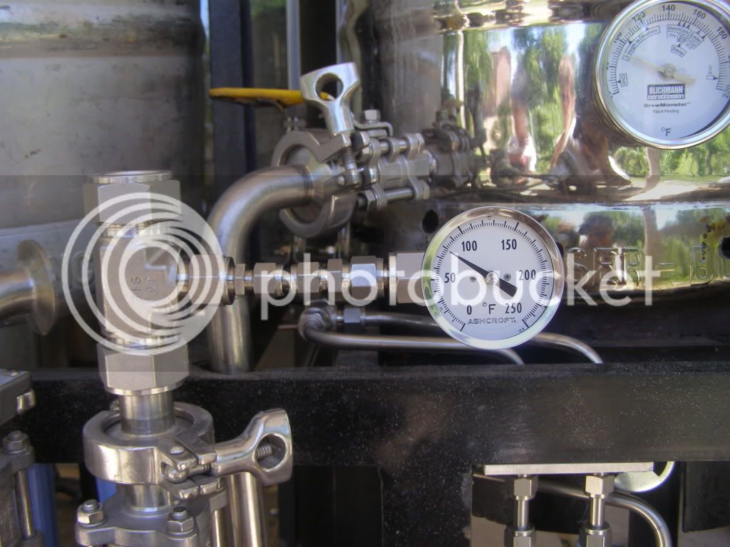
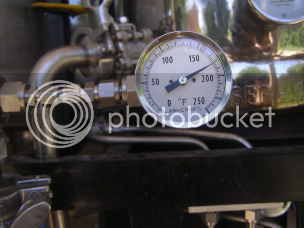
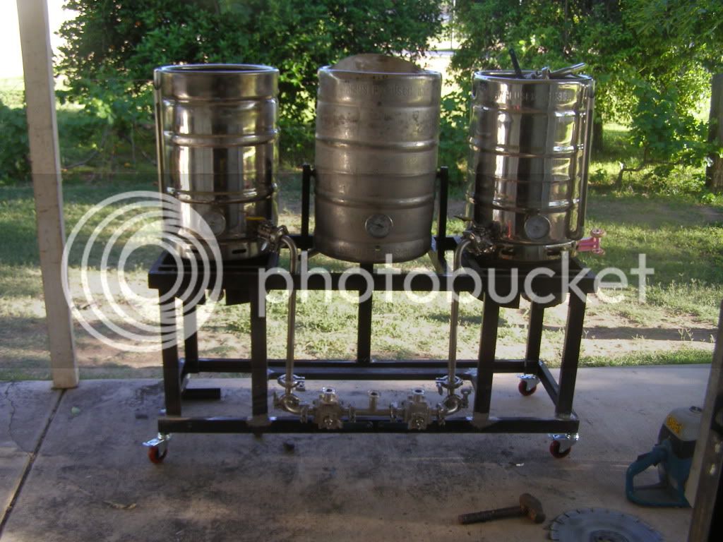
Here is the stand at it's new better height with proper casters with the lower wort manifold installed. The valves are three way and allow wort to be directed to either pump from any of the three kettles. With sight glasses and thermometers installed. also notice the vent holes in the lower keg skirt.
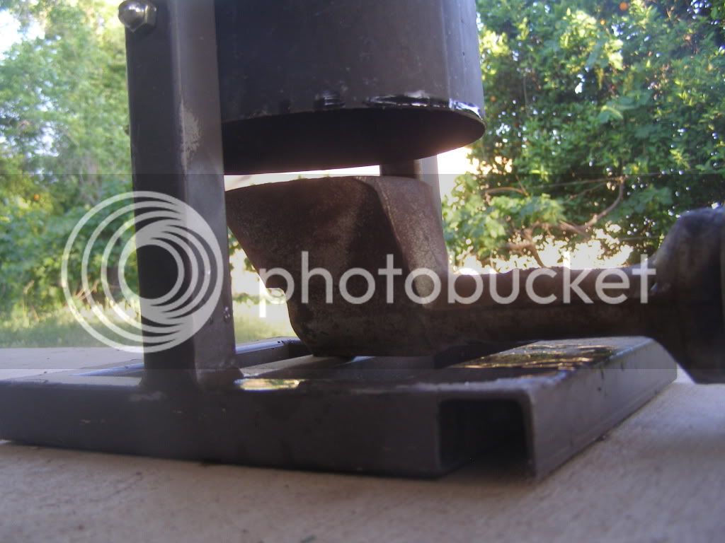
And the tippie dump.
Thanks for lookin I'll post more tomorrow.
Just to bring you all up to date, my original plan was a single tier, steam infused mash setup powered by a pressure cooker that I modified for steam bending wood. Including a tippie dump, two pumps, hard pipe plumbing,and 100 percent manual. I like the human aspect of brewing.
I have made a few changes to the original plan mainly the pressure cooker idea has been replaced by a Flash Boiler simillar to Klaude's and Green Montie's. Mine is four 20' lengths of 1/4" soft copper tubing. Also I scored a bunch of Tri Clover fittings, valves etc. at the local scrap yard for 88 cents per pound!!! I bought about 400 lbs worth and sold off the stuff I didn't need to recoup my investment. With a heaping pile of Tri Clover pipe and fittings i began to piece together my plumbing.
My main justification for starting this new thread is that I have not seen any body hard pipe a rig with Tri Clovers. Also I think my rig very visualy shows the wort flow path and I think this might help people thinking of doing somthing similar. Also the manual flash boiler settup is fairly simple without all the electronic gagetry to confuse the actuall prosess. over the next couple of weeks I will post up pictures and methods. If you have any questions or comments, speek up and I will do my best to answer all. I want to document this build as detailed as posible, and doing it sort of after the fact I might leave somthing out.
P.S. The computer is a tool I am not very good with, so bear with me keeping up with my slow fingers.
Here is the original stand configuration. I got rid of the wood panels, one caught fire while testing the burner. I also had to move the center uprights closer to the outside to accommidate the Tri clover plumbing. The stand was welded with an old rusty stick welder that I found in a ditch at one of my brothers investment propertys. The keggle on the left was the 1st one i built I welded the band around the top with alumnum wire, I thaught kegs were aluminum. I still brewed a few batches on it!!!
Some of the Tri Clover stuff from the scrap yard.
Drilling kegs for valves.
The inside of my one usable keggle.
Here I am cutting the stand down for the seconed time. This saw is sweet I have used it to cut cars into movable pieces in the past.
Here is the stand at it's new better height with proper casters with the lower wort manifold installed. The valves are three way and allow wort to be directed to either pump from any of the three kettles. With sight glasses and thermometers installed. also notice the vent holes in the lower keg skirt.
And the tippie dump.
Thanks for lookin I'll post more tomorrow.