Review my wiring diagram? (BruControl fermentation automation)

Homebrew Talk - Beer, Wine, Mead, & Cider Brewing Discussion Forum

Help Support Homebrew Talk - Beer, Wine, Mead, & Cider Brewing Discussion Forum:

This site may earn a commission from merchant affiliate links, including eBay, Amazon, and others.

sensei247

Active Member
Joined
Jun 4, 2020
Messages
38
Reaction score
2
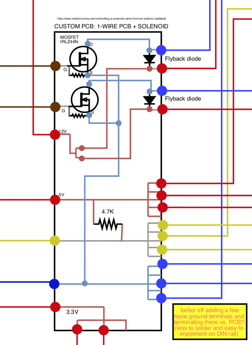
Hi All- I have finally decided to pull the trigger on automating my brewhouse. Starting with the cold side as I am a few months out from ordering my LODO Stout kettles. Cold side seems like an easier place to shake off the rust from my (light) comp sci/electrical eng university studies....

Overall goal: automate cold side fermentation end to end. "End to end" = starts when wort leaves the BK and enters FV THROUGH to keg transfer and finally spunding (if desired). I am also trying to manage vacuum issues by integrating CO2 solenoid to adjust FV pressure when temperature drops and pressure approaches vacuum.

This isn't a fully complete build as I plan to add on to this in the future (e.g. automated dry hopping, automated yeast dumps, etc.). Trying to keep this in mind with the larger relay, terminal, etc. buses.

--Call it overkill because it is.--

3 of main concerns right now include:
1) HV: First time working and integrating high voltage through breakers, PSUs, downstream electronic components, etc. In this case, 110V input voltage to panel. - want to ensure this wiring is correct (left side of image)
2) Electronic components: First time working with MOSFETs and flyback diodes. Not sure the relay is setup correctly either- want to ensure solenoid wiring and other sensor wiring is correct (right side of image)
3) Safety: Overall, is this something I can safely run without risk of electrocution, fire, etc.? - are there any other safety components I am missing or not wired in correctly?

Any chance you can offer any and all feedback on my fermentation controller wiring diagram? Thanks in advance 🙂

----------------------------------------------------------------------------------------------------------------------------------------------
----------------------------------------------------------------------------------------------------------------------------------------------

Master schematic:
1601161358175.png


Close up - custom circuit board:
1601140747475.png
 
Last edited:
I highly recommend to add resistors between pin and MOSFET gate to protect ESP pin from overcurrent plus pull down restore top keep MOSFET closd when pin is not configured. Something like this (but remove D3)

1601328578797.png

Secondly 3.3V is not enough to fully open IRLZ44N . So you it could be possible that 12V power supply will not engage solenoid.
 
Last edited:
@brumateur1 Thanks for the thoughts here. This is super helpful. To summarize, seems like there are 2 protections we are taking:
1. Prevent ESP from overcorrect BACK into ESP through pin 23
2. Prevent EMI by adding in a pull down resistor to ensure MOSFET stays closed when pin is not configured (e.g. ESP just turning on, EMI, etc.)

2 questions:
1. Any thoughts on the updated view below?

- I'm not sure what size resistor should be used for the "Protects from overcorrect" pin (right now, 120mA = 10x impedance of digital pin...again, not sure this is correct)
- I think the pull down resistor was already in place- this would be the 10K resistor between gate and tied into the same ground that source would run through.
2. How would I re-wire this per your comment that 3.3v is not going to be enough to operate the MOSFET?
1601345917105.png

[/QUOTE]
 
- I'm not sure what size resistor should be used for the "Protects from overcorrect" pin

Something like 100-200 Ohm is enough.

- I think the pull down resistor was already in place- this would be the 10K resistor between gate and tied into the same ground that source would run through.
Yes, I just overlooked it.

2. How would I re-wire this per your comment that 3.3v is not going to be enough to operate the MOSFET?


I didn't say 3.3V is not enough to operate this MOSFET. It just will not be open fully just partially. May be it would be enough to operate your coil or may be not. If you have your coil handy I can suggest to create test circuit using breadboard. Just put there MOSFET, couple mentioned resistors and connect it to coil and 12V power supply. Then connect 3.3 source between GND and 100-200 Ohm resistors. You can use a 3v3 pin of you ESP 32 or even coin battery. And check if your valve works a s expected.
 
Last edited:
Something like 100-200 Ohm is enough.


Yes, I just overlooked it.
2. How would I re-wire this per your comment that 3.3v is not going to be enough to operate the MOSFET?[/QUOTE]

I didn't say 3.3V is not enough to operate this MOSFET. It just will not be open fully just partially. May be it would be enough to operate your coil or may be not. If you have your coil handy I can suggest to create test circuit using breadboard. Just put there MOSFET, couple mentioned resistors and connect it to coil and 12V power supply. Then connect 3.3 source between GND and 100-200 Ohm resistors. You can use a 3v3 pin of you ESP 32 or even coin battery. And check if your valve works a s expected.
[/QUOTE]
Perfect- sounds great. Will give this a go. Really appreciate your input. Any other major issues you see with the diagram (especially high voltage side)?
 
If the 3.3V doesn't open the MOSFET enough to operate the valve, then look at sticking a MOSFET driver like the TC1410 or similar between the ESP 32 and the MOSFET. It'll also help with protecting the MOSFET from the digital noise of the ESP.
 
If the 3.3V doesn't open the MOSFET enough to operate the valve, then look at sticking a MOSFET driver like the TC1410 or similar between the ESP 32 and the MOSFET. It'll also help with protecting the MOSFET from the digital noise of the ESP.

Why not choose a different mosfet with lower Vgs threshold such that 3.3V will turn on the mosfet fully?
 
Most likely IRLZ44N will work OK, but it depends on coil parameters. So it's better to do a test before starting panel assembling .
 
Why not choose a different mosfet with lower Vgs threshold such that 3.3V will turn on the mosfet fully?

Primarily if he's already got the mosfets, then cost of a driver chip over replacing the mosfets.

A secondary concern is potentially the fragility of the 3.3V mosfet, lower current (Id) and voltage (Vdss) specs in the ones I've seen.

Thirdly, it reduces the current load on the output pins of the ESP 32.
Thanks for the great thoughts here. Would I be better off with a IRLML6344? Looking at the specs it appears I can use a 0-3.3V at gate. Thoughts?
 
Thanks for the great thoughts here. Would I be better off with a IRLML6344? Looking at the specs it appears I can use a 0-3.3V at gate. Thoughts?

Sure, ut will work OK with 3.3V Vgs. However its can provide only 4Amp of continuous load. Should be enough for most valve's solenoids but I'd doublecheck.
 
Back
Top