Humuleneman
Active Member
- Joined
- Sep 23, 2014
- Messages
- 40
- Reaction score
- 6
I just finished my counter flow chiller to cool my wort. I took 1/2 ID copper tubing. About 25 feet. I decided to weld copper wire in spiral around it. i took some 12 gauge electrical wire and stripped the plastic around it. i then coiled it around the tube with a turn every 3 inches. i did a spot soldering every 4 inch or so leaving 1 1/2 foot foot of tubing a each ends with no wire. I heard this wire is supposed to break laminar flow on the copper tube surface so it gives a better heat exchange between the water and the wort. I then slided with some dish washing soap to help a braided 1 inch flexible tubing on the copper. It was about 1 feet shorter on both ends. the next tricky part was the connector on both ends.
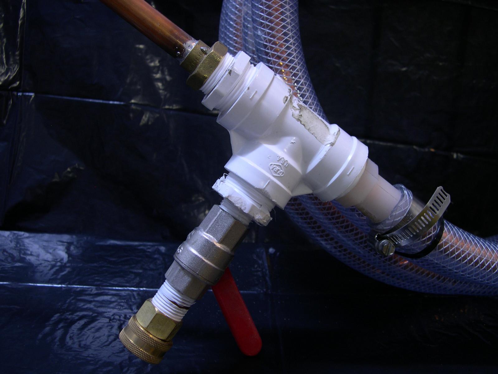
my plan was to weld on the copper pipe to a 1/2 inch x 3/4 NPT brass fitting. Unfortunately those come with a small ring inside that prevent the copper pipe to slide right through. I was easily removed using a step bit. I then used a T made of PVC to connect the fitting. Now the tricky part. how to weld it in place without melting the plastic. the first side was easy .Welding, cooling, teflon tape and voila. the other side was more of a brain puzzle. on the inside part of the two T's, i've use a 3/4 inch NPT to barb nylon fitting. I used also some silicon grease to help sliding the braided hose on it. The barbed part of the nylon fitting was about 2 inch long. It allowed me to push really far the braided hose on the side already welded leaving about 2 inches of naked copper pipe. now how to prevent the heat from the welding not to go along the copper pipe and melt the PVC fitting? I've taken a trick from electronics part welding. You need a mass to drain or accumulate this heat. I took 2 wise lock pliers and gently clipped them between the part to weld and my plastic T. I did the weld and cooled it fast cold air (my girl friend hair drier!) all the heat from the weld went in the pliers and all the plastic parts were saved. I've screwed the T on the brass fitting. Slided back the braided hose on the Nylon barb. Screwed some hose clamps. (if you can, slide those on before welding. It saves trouble!) I then coiled this thing around a big metal drum. (more then a feet of diameter). It prevented some kinks on the copper pipe. I then screwed on a valve with a garden hose connector and done. It did a leak test. everything seems ok. I can see the water swirling inside the hose. The next step will be to solder on both ends a 1/2" pipe to 1/2 NPT and screw a camlock fitting and do a temperature test.

my plan was to weld on the copper pipe to a 1/2 inch x 3/4 NPT brass fitting. Unfortunately those come with a small ring inside that prevent the copper pipe to slide right through. I was easily removed using a step bit. I then used a T made of PVC to connect the fitting. Now the tricky part. how to weld it in place without melting the plastic. the first side was easy .Welding, cooling, teflon tape and voila. the other side was more of a brain puzzle. on the inside part of the two T's, i've use a 3/4 inch NPT to barb nylon fitting. I used also some silicon grease to help sliding the braided hose on it. The barbed part of the nylon fitting was about 2 inch long. It allowed me to push really far the braided hose on the side already welded leaving about 2 inches of naked copper pipe. now how to prevent the heat from the welding not to go along the copper pipe and melt the PVC fitting? I've taken a trick from electronics part welding. You need a mass to drain or accumulate this heat. I took 2 wise lock pliers and gently clipped them between the part to weld and my plastic T. I did the weld and cooled it fast cold air (my girl friend hair drier!) all the heat from the weld went in the pliers and all the plastic parts were saved. I've screwed the T on the brass fitting. Slided back the braided hose on the Nylon barb. Screwed some hose clamps. (if you can, slide those on before welding. It saves trouble!) I then coiled this thing around a big metal drum. (more then a feet of diameter). It prevented some kinks on the copper pipe. I then screwed on a valve with a garden hose connector and done. It did a leak test. everything seems ok. I can see the water swirling inside the hose. The next step will be to solder on both ends a 1/2" pipe to 1/2 NPT and screw a camlock fitting and do a temperature test.

Last edited:


