My Fermentrack Build

Homebrew Talk - Beer, Wine, Mead, & Cider Brewing Discussion Forum

Help Support Homebrew Talk - Beer, Wine, Mead, & Cider Brewing Discussion Forum:

This site may earn a commission from merchant affiliate links, including eBay, Amazon, and others.

garzlok

Supporting Member
HBT Supporter
Joined
Aug 19, 2012
Messages
467
Reaction score
378
Location
Dacula
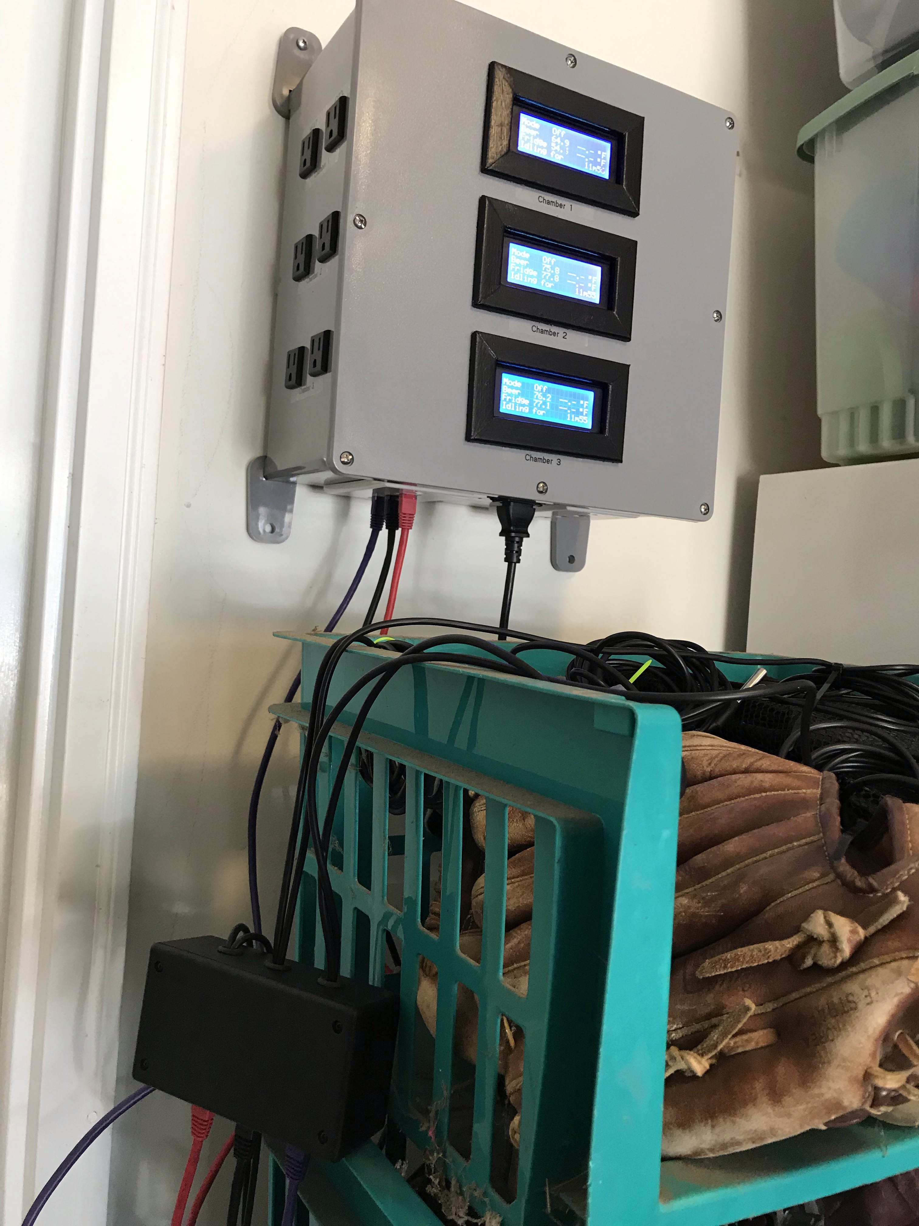
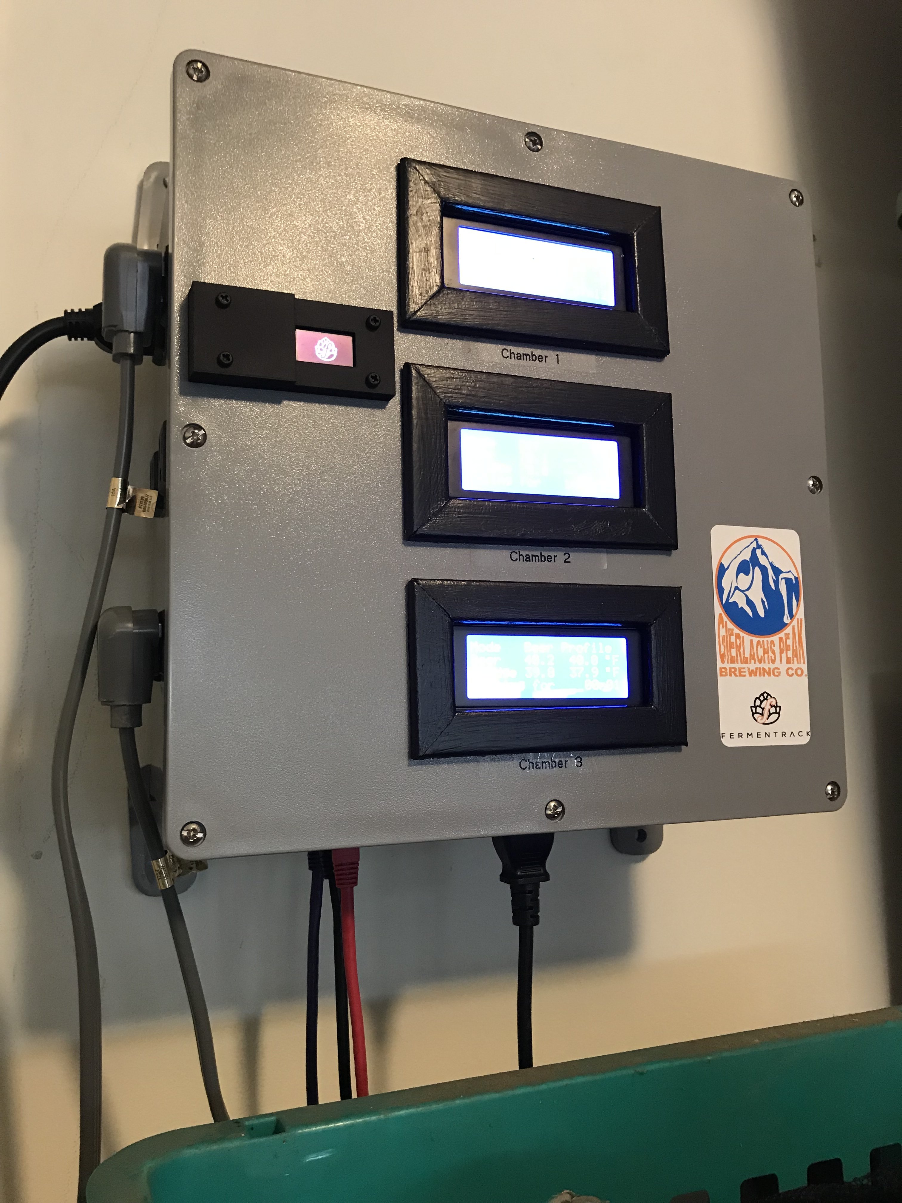
I’ve found that some of the most active DIY threads revolve around fermentation control, be it with Fermentrack, BrewPi Remix, BrewPi Less, etc. These threads are a huge trove of information and great resources. The one thing I noticed, not too many build threads. For a novice like me, I love the build threads. I thought I would just take the time to share my experience as I built my Fermentrack Control Panel.

This should go without saying, but please use the following references as the “go to” authority for all things Fermentrack.

fermentrack.com
docs.fermentrack.com/en/master
GitHub.com/thorrak/Fermentrack
YouTube.com (Optictheory)

My build can be broken down into 4 major phases. I am not going to spend much time talking about Phases 1 and 4. Those are extremely well documented, but I will add some tidbits from my experience that may help someone out along the way.

Phases:
  1. RaspberryPi Set-Up/Fermentrack Installation
  2. RJ45 Breakout Board Control Box Build
  3. 3 Instance Main Control Box Build
  4. Controller Flashing/Controller WiFi Connection Set-up/Add Temp Controller
I did not add quantities for items. My build is a 3 Instance Fermentrack project. Your item quantities and Project Box sizes will vary and be determined by your project. Breakout boards were ordered using Thorraks’ Designed PCBs through pcbs.io.

B.O.M.
  • ESP8266 Breakout Board for BrewPi - SMD w/ LCD & RJ45 v1.0 (pcbs.io)
  • RJ45 Sensor Breakout v1.0 for ESP8266-based BrewPi controllers (pcbs.io)
  • New High quality AC 100-265V to DC 5V 2A Switching Power Supply Module TL431(AliExpress)
  • 2 channel relay module 5V 2-channel relay modules 5VDC 2 road relay module control board with optocoupler (AliExpress)
  • Character LCD Display Module 20x4 LCD2004 IIC/I2C/TWI 2004 Display PCF8574 for Arduino Uno r3 Mega 2560 Raspberry Pi Avr Stm32 (AliExpress)
  • LOLIN D1 mini V3.1.0 - WEMOS WIFI Internet of Things development board based ESP8266 4MB MicroPython Nodemcu Arduino Compatible (AliExpress)
  • 3M DS18B20 Digital Temperature Temp Sensor Probe Thermometer Waterproof Sensor Compatible For Arduino Stainless Steel (AliExpress)
  • 5.08-301-2P 301-2P 2 Pin Screw Terminal Block Connector 5mm Pitch (AliExpress)
  • 1206 SMD capacitor 100uf 16V 107Z X7R (AliExpress)
  • 0805 SMD 1/4W 0R ~ 10M chip resistor 4.7K (AliExpress)
  • 0805 SMD 1/4W 0R ~ 10M chip resistor 10K (AliExpress)
  • BSS138LT1G BSS138 SOT23 SOT SOT23-3 MOSFET SMD (AliExpress)
  • Single Row Male and Female 2.54 Breakable Pin Header PCB JST Connector Strip (AliExpress)
  • Dupont Line 30CM Female to Female Jumper Wire Dupont Cable (AliExpress)
  • Black 3 Pins IEC320 C14 Inlet Power Plug Socket AC 250V 10A (AliExpress)
  • US 3 Pin Power Socket Panel Receptacle AC125V 15A, UL Cert (AliExpress)
  • RJ45 8P8C Black Computer Internet Network PCB Jack Socket (AliExpress)
  • Keystone Plates (Frys Electronics)
  • USB Keystone Jack Inserts (Amazon)
  • RJ45 Keystone Jack Inserts (Frys Electronics)
  • 1ft Ethernet Patch Cables (Frys Electronics)
  • 3ft Ethernet Patch Cables (Frys Electronics)
  • USB Male A to Micro USB B Male Cable (Frys Electronics)
  • NEMA 5-15P/C13 Power Cord (Frys Electronics)
  • USB Male A to USB Male A Cable (Amazon)
  • Push-In Wire Connectors (Home Depot)
  • AMP Female Disconnects (Home Depot)
  • 14AWG Solid Strand Wire (Black, White, and Green) (Home Depot)
  • 12in x 12in x 6in Junction Box (Home Depot)
  • 5in x 3in x 2in Project Box (Micro Center)
  • M3 Nylon Screws and Nuts (Micro Center)
  • RaspberryPi 3B+ w/ Power Cord, SD Card & Case (Micro Center)
  • Back-up SD Card (Micro Center)
 
Phase 1
Raspberry Pi Set-Up/Fermentrack Installation

This was my first experience with anything RaspberryPi. I decided to install the Lite Version of the Raspbian OS (Stretch). Though I experienced no issues, I found myself later wishing I had installed the full version. If you are new to RaspberryPi, my recommendation is to use the full version. The full version has a nifty backup app preinstalled, SD Card Copier (which I eventually installed) and a GUI (which I eventually installed).

The ability to complete easy backups is a necessity. Though I have yet to experience an SD Card failure, reading through these forums, SD Card failure appears to be inevitable. Make backing up as easy as possible on yourself!

For a reason I did not expect, I found a need for a GUI. RaspberryPi/Fermentrack work off a Home Network. I travel...I travel a lot, and I had no plans to set-up port forwarding and blow holes through my network security just so I can geek-out over a fermentation process. Then I learned about VNC Viewer and Remot3.it. In a nutshell VNC allows me to both locally and remotely connect to my RapberryPi. Remot3 allows me to access Fermentrack from a remote location. Both are secure services that are worth investigating if you feel the need.

The catch? If you want to use the Free.99 Home Version of VNC Viewer, your RaspberryPi has to have a GUI and cannot be headless. If you are willing to pay for the Enterprise Version of the VNC viewer, than you can have a headless version of Raspbian. Me? Add the GUI and go the Free route.
 
Phase 2
RJ45 Breakout Board Control Box Build

Ultimately, I want to close up my fermentation control box and forget about it. I don’t want to go in and connect USB cables to my D1 Mini or if a temp probe goes bad, have to open up, rewire, and swap-out probes.

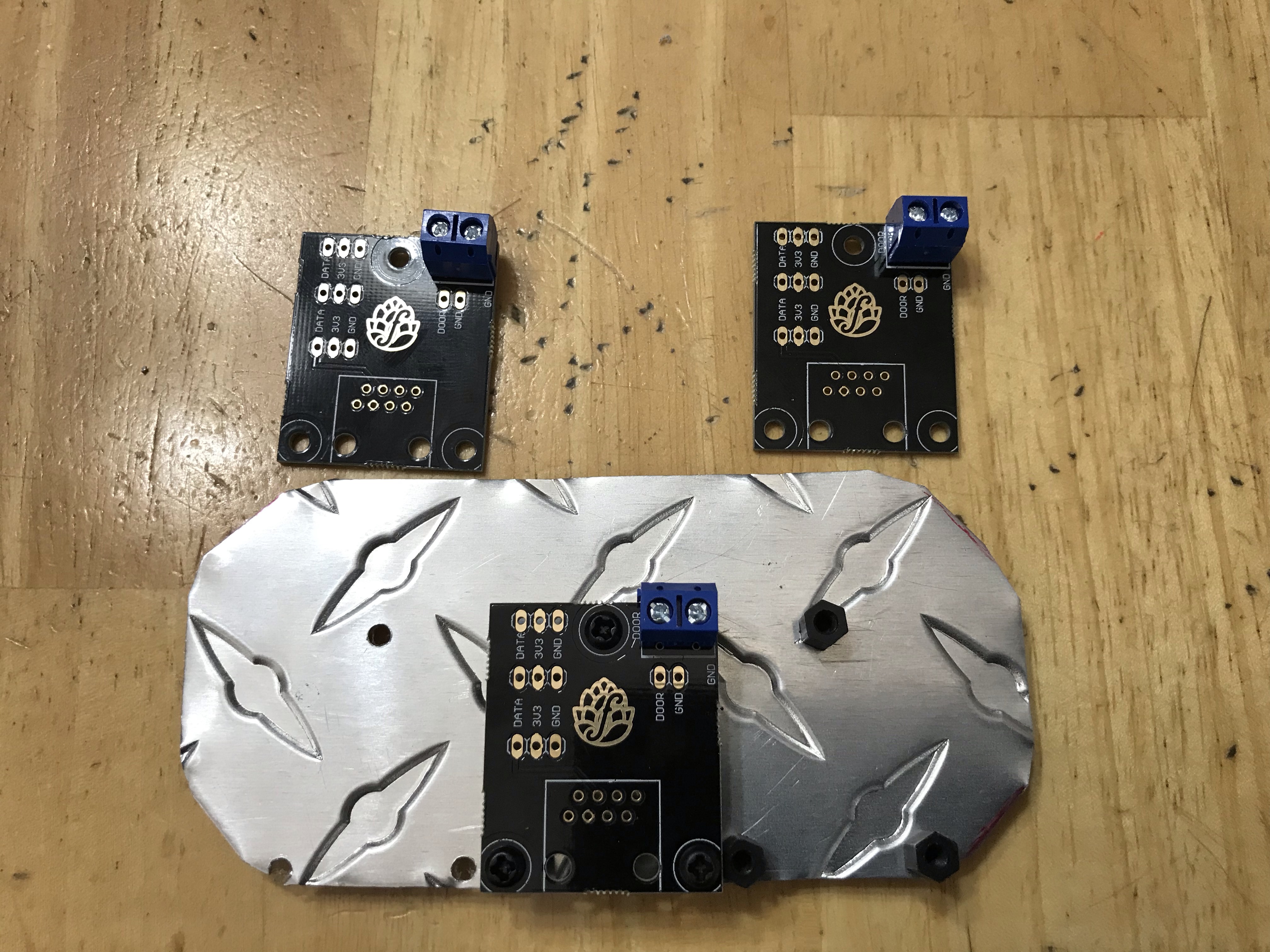
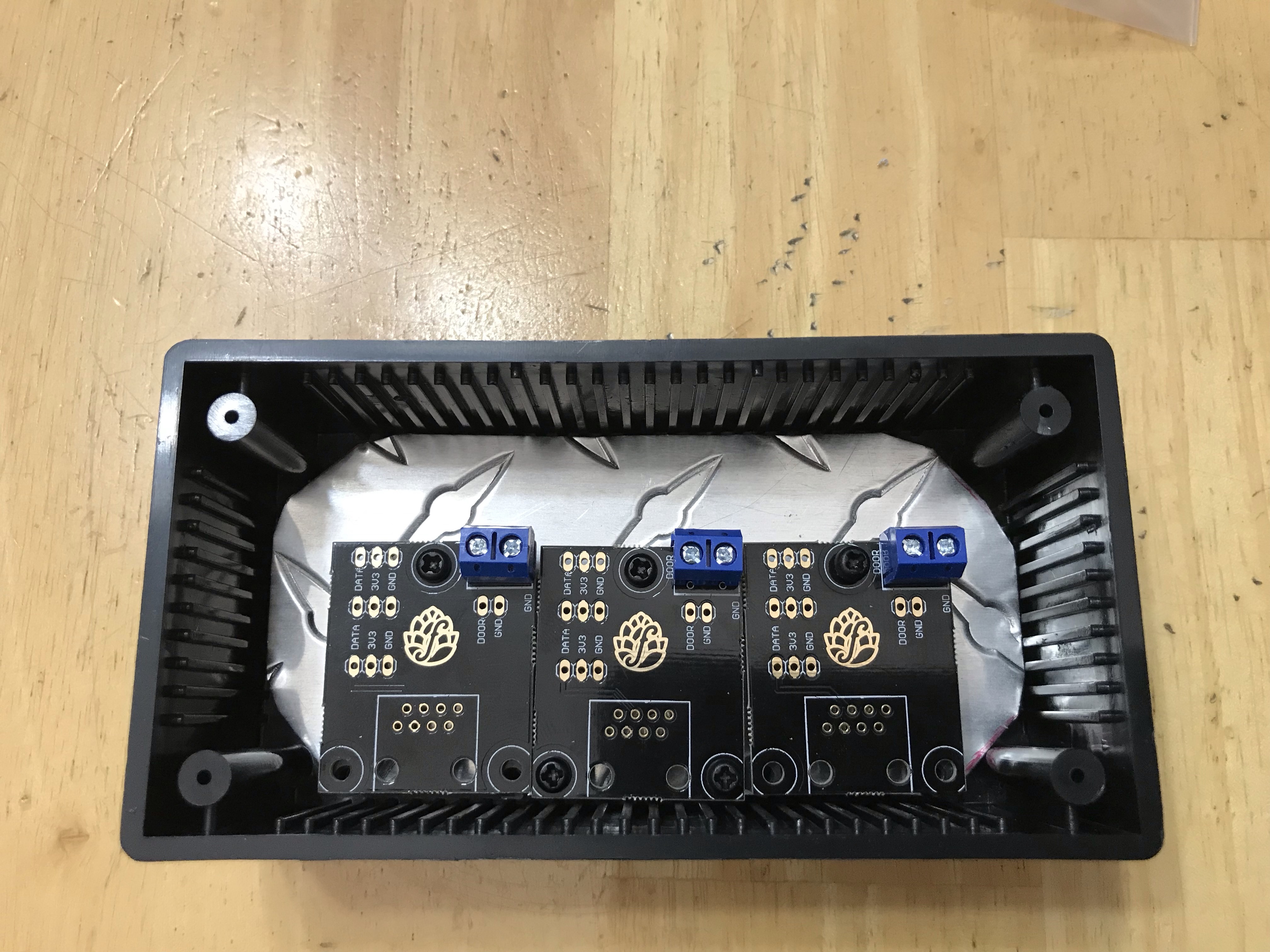
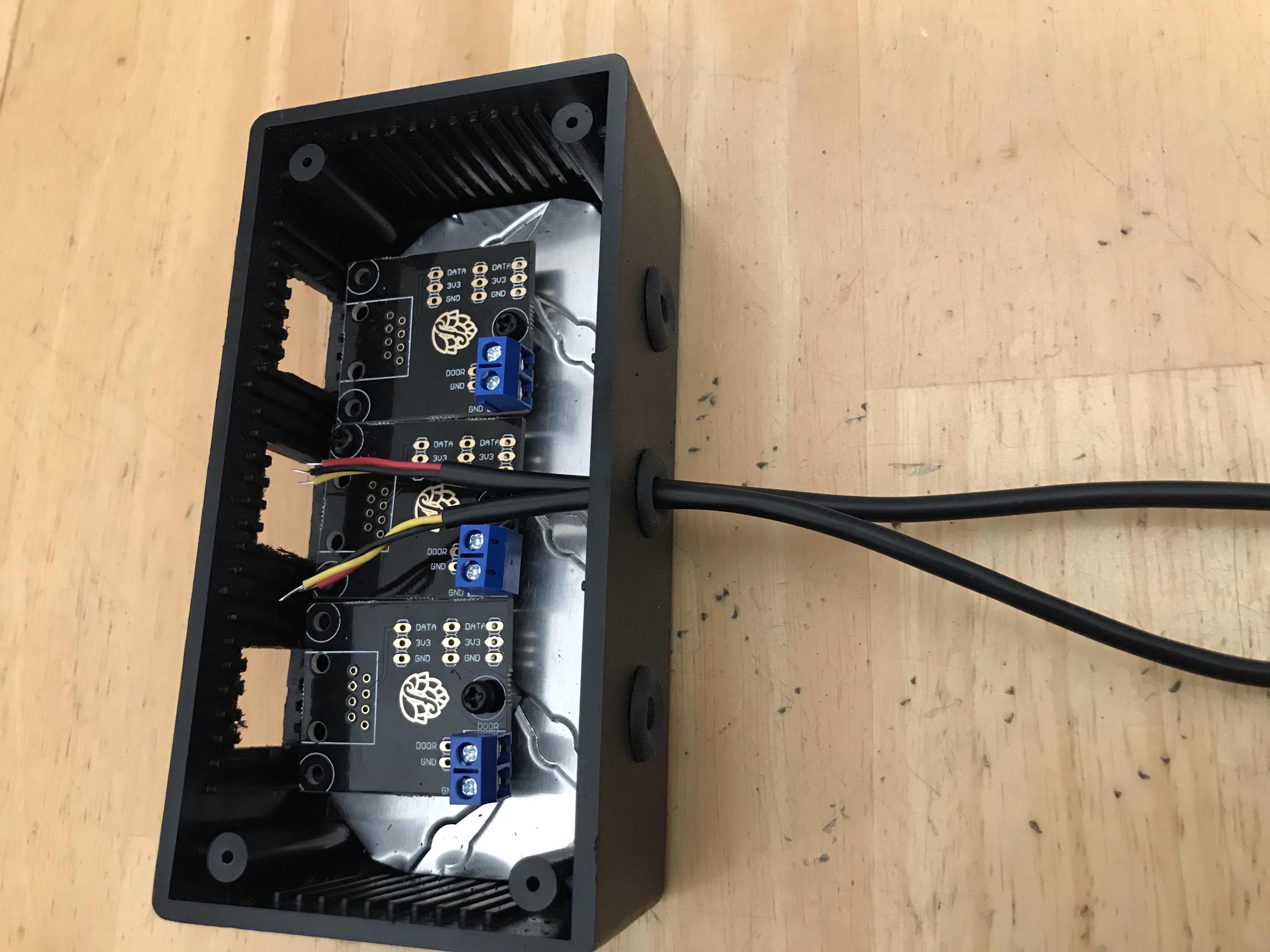
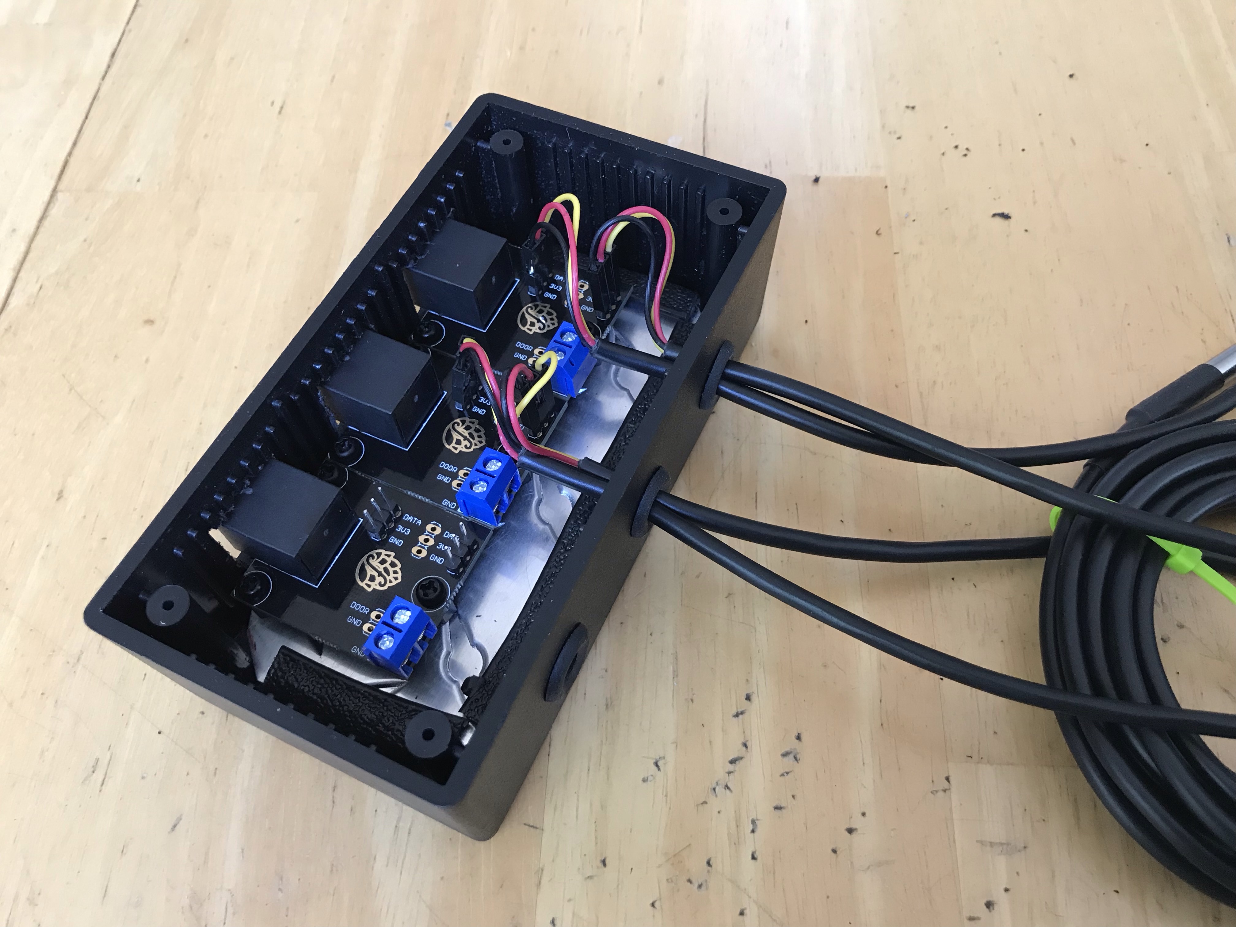
Since the PCB is called an RJ45 Sensor Breakout, I thought I would create an RJ45 Breakout Board Control Box. I would run three (3) pairs of DS18B20 Temperature Probes into one project box. The project box would contain three (3) RJ45 Sensor Breakout PCBs. A pair of probes would be connected to an RJ45 Sensor Breakout PCB. An Ethernet cable (x3) would connect an RJ45 Sensor Breakout Board to the Main Control Box.
  1. Purchase a project box that is large enough to comfortably hold as many RJ45 Sensor Breakout PCBs as desired
  2. Cut a piece of Aluminum to fit inside project box to act as a sub-board.
  3. Place PCBs on aluminum and mark mounting hole locations.
  4. Drill holes in aluminum where mounting holes were marked.
  5. Add standoffs to mounting holes.
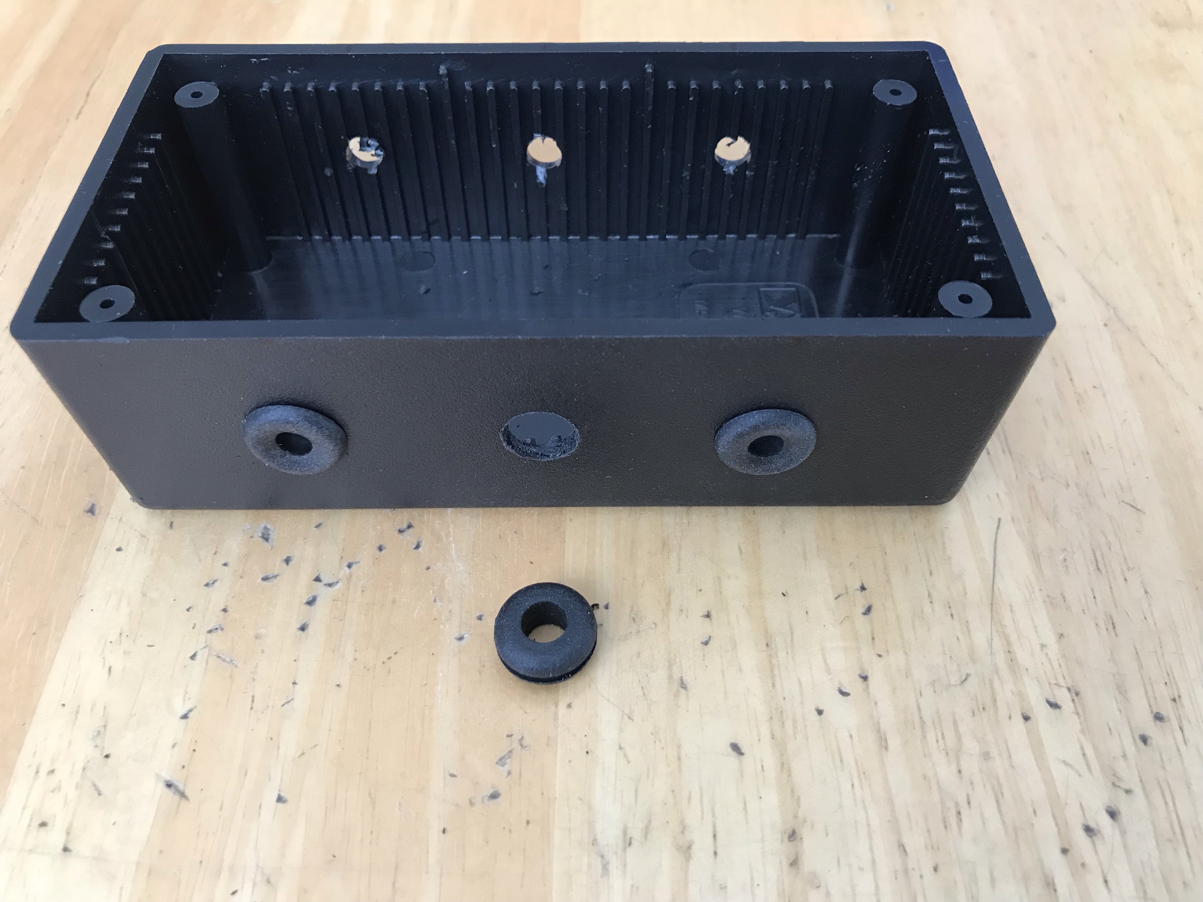
  6. Drill hole(s) large enough to allow 2 temperature probes/hole through.
  7. Install grommets onto the holes
  8. On opposite side of the temperature probes, drill pilot holes lining up with RJ45 Jack on PCBs.
  9. Using pilot holes as a guide, cut opening to fit RJ45 Socket.
  10. On the DS18B20 probes, add Female DuPont connectors to the exposed wire ends.
  11. Solder the following on the RJ45 Sensor Breakout PC
    1. RJ45 PCB Socket
    2. 2-pin Screw Terminal Block
    3. Male Pin Headers to the Data, 3v3, and Gnd locations on the PCB
  12. Secure completed RJ45 PCBs to the standoffs.
  13. Insert aluminum sub-board with RJ45 PCB(s) into project box
  14. Thread DS18B20 Wire ends through the grommets
  15. Attach DS18B20s to the appropriate Data, 3v3, and Gnd location on the PCBs
  16. Close the project box
  17. Connect Ethernet patch cables to the RJ45 sockets.
  18. Run Ethernet patch cables to the main control box.
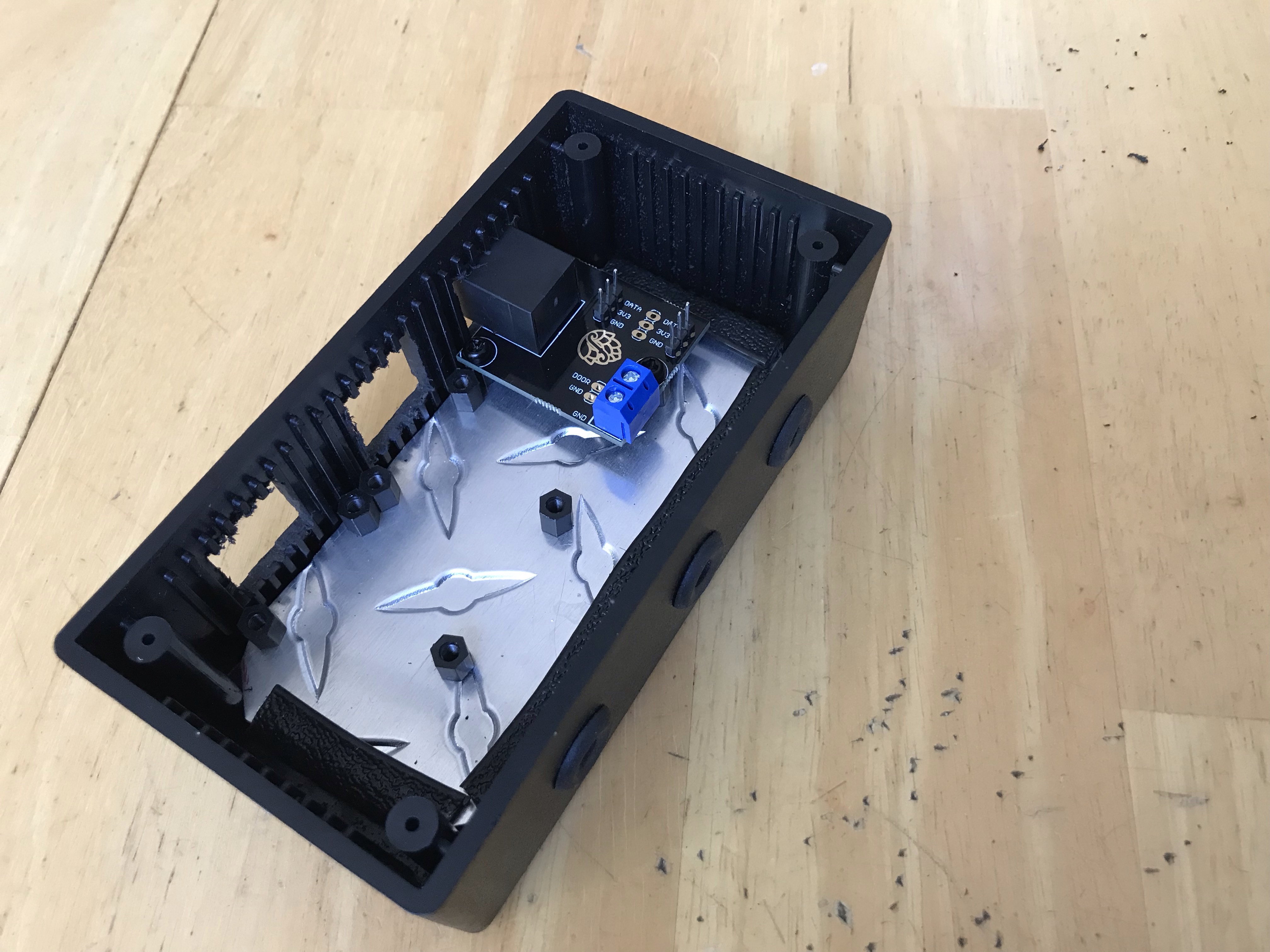
2_1.jpg


2_2.jpg


2_3.jpg


2_4.jpg


2_5.jpg


2_6.jpg


2_7.jpg

2_8.jpg
 
Last edited:
Phase 3
3 Instance Main Control Box Build

As I said in Phase 2, I really don’t want to have to open and enter the project box holding the controllers. If I want to flash a D1 Mini, I don’t want to open the box. If a temperature probe goes bad, I don’t want to open the box.

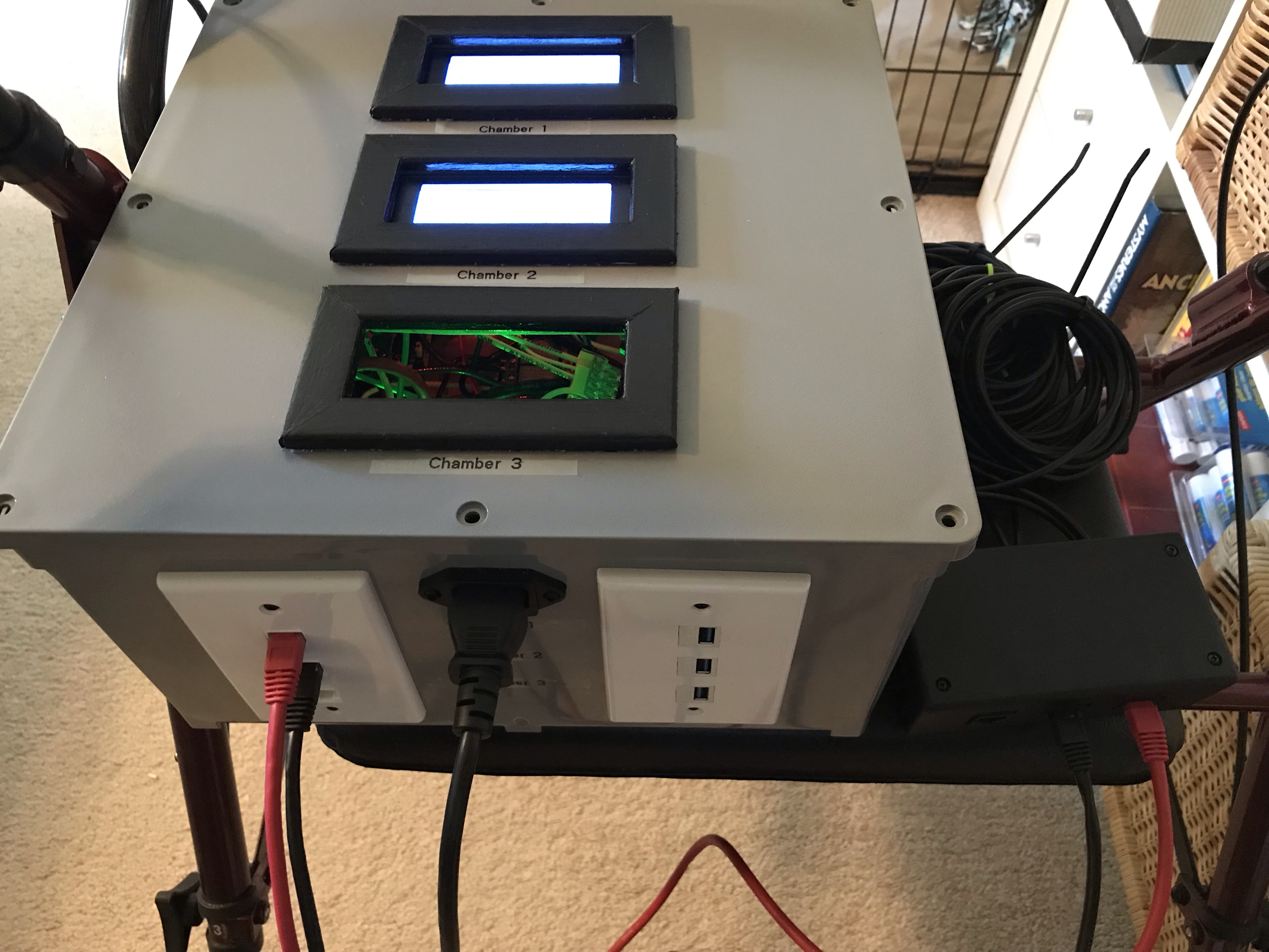
I only have one (1) fermentation cooler, but a second will be added. I also currently have a fridge used to lager (hold Temp at 40F). With an eye to the future, this is a 3 instance build. Two (2) controllers will be held at Beer Constant/Profile and one (1) controller will be at Fridge Constant.

Looking at the module sizes and how I wanted to position the modules, I decided on a 12” x 12” x 6” Junction Box. This box is huge and I thought I made a mistake going with the larger box. As I assembled the control box, for me, this was the perfect size for a 3 instance control box.
  1. Purchase a project box that is large enough to comfortably hold as many Controller Instances as desired
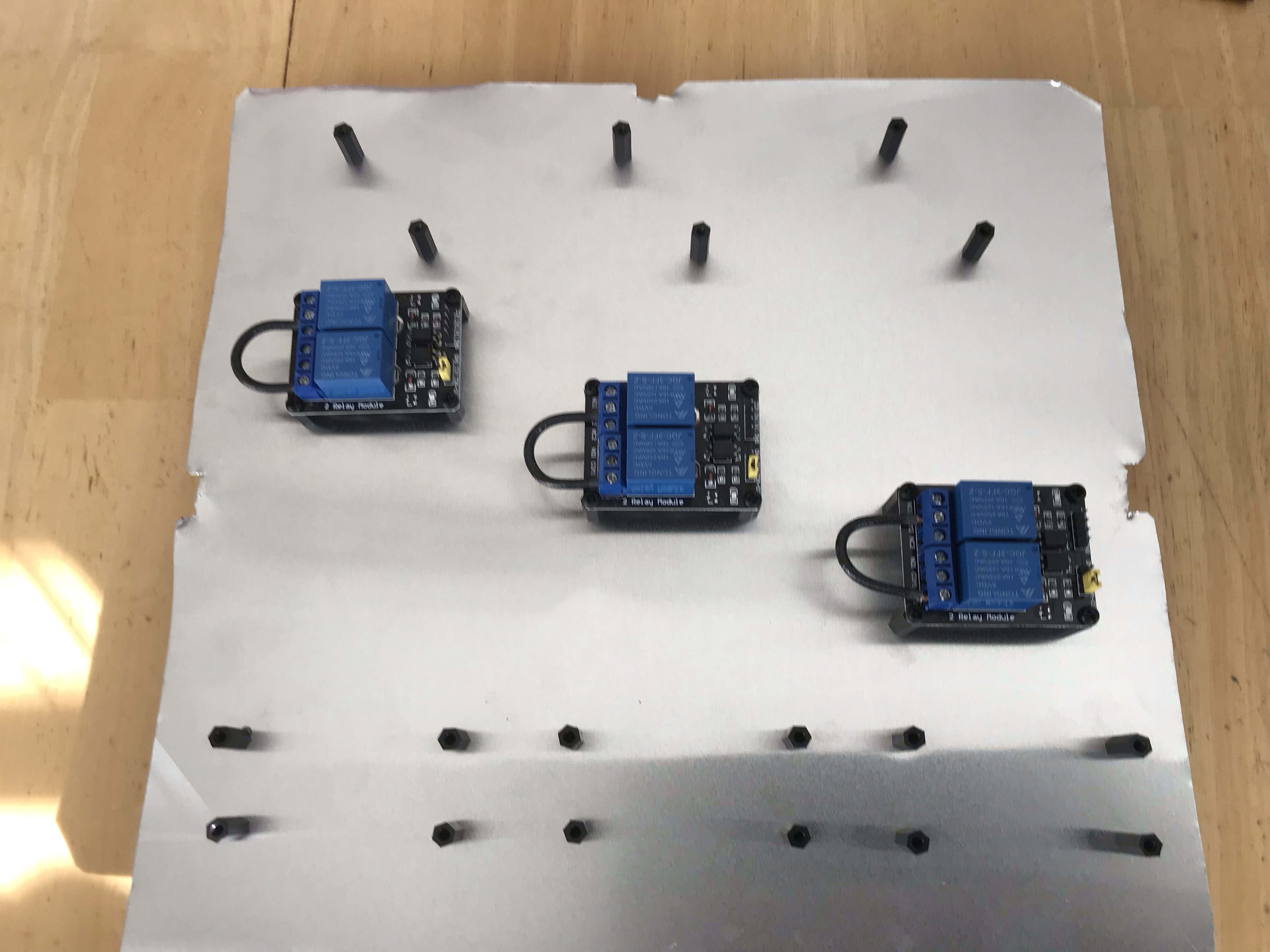
  2. Cut a piece of Aluminum to fit inside project box to act as a sub-board.
  3. Place Modules on aluminum and mark mounting hole locations.
  4. Drill holes in aluminum where mounting holes were marked.
  5. Add standoffs to mounting holes.
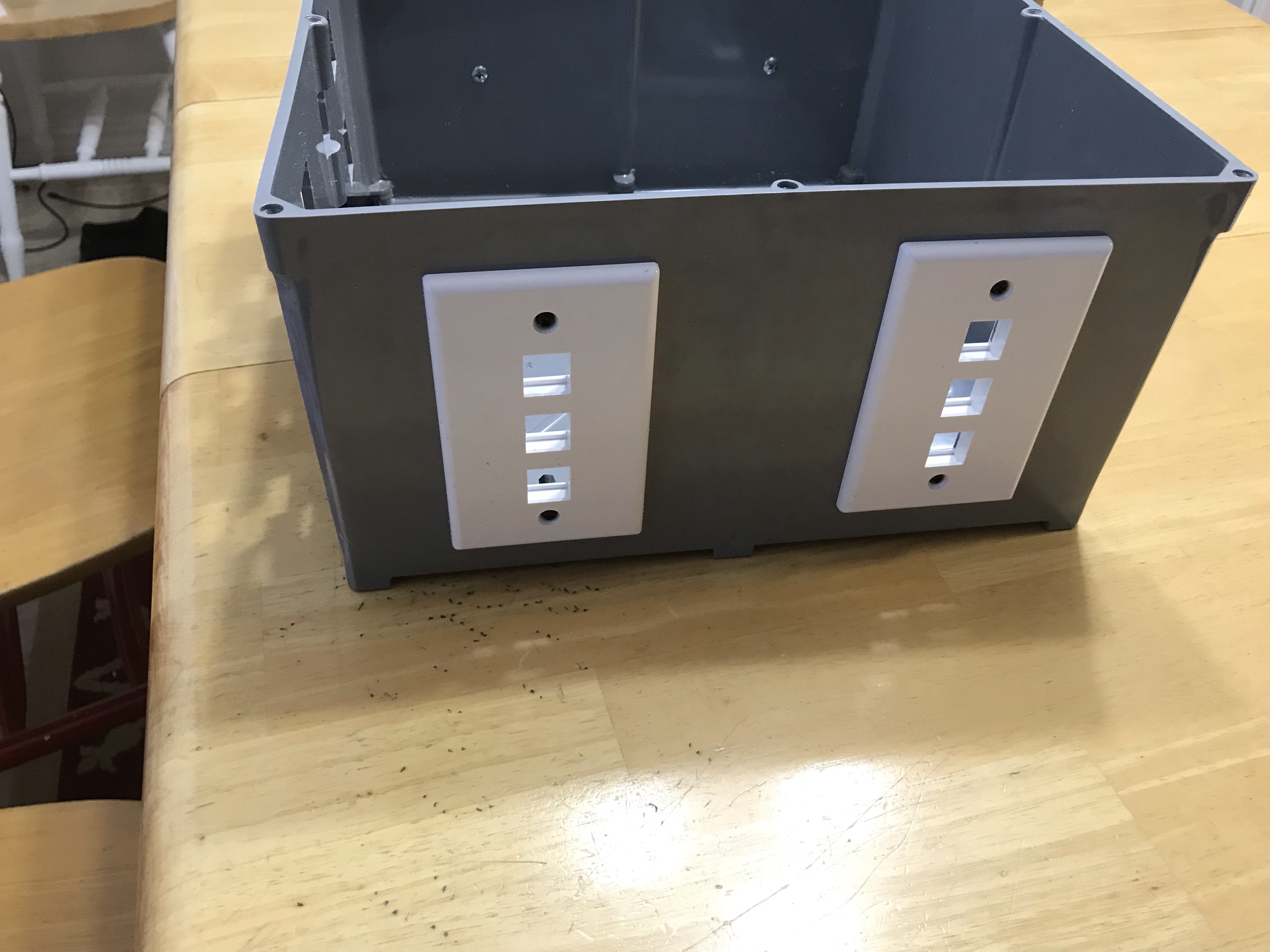
  6. Determine location of Keystone Plate(s)
  7. Cut opening to fit Keystone Plate(s)
  8. Install Keystone Plate(s)
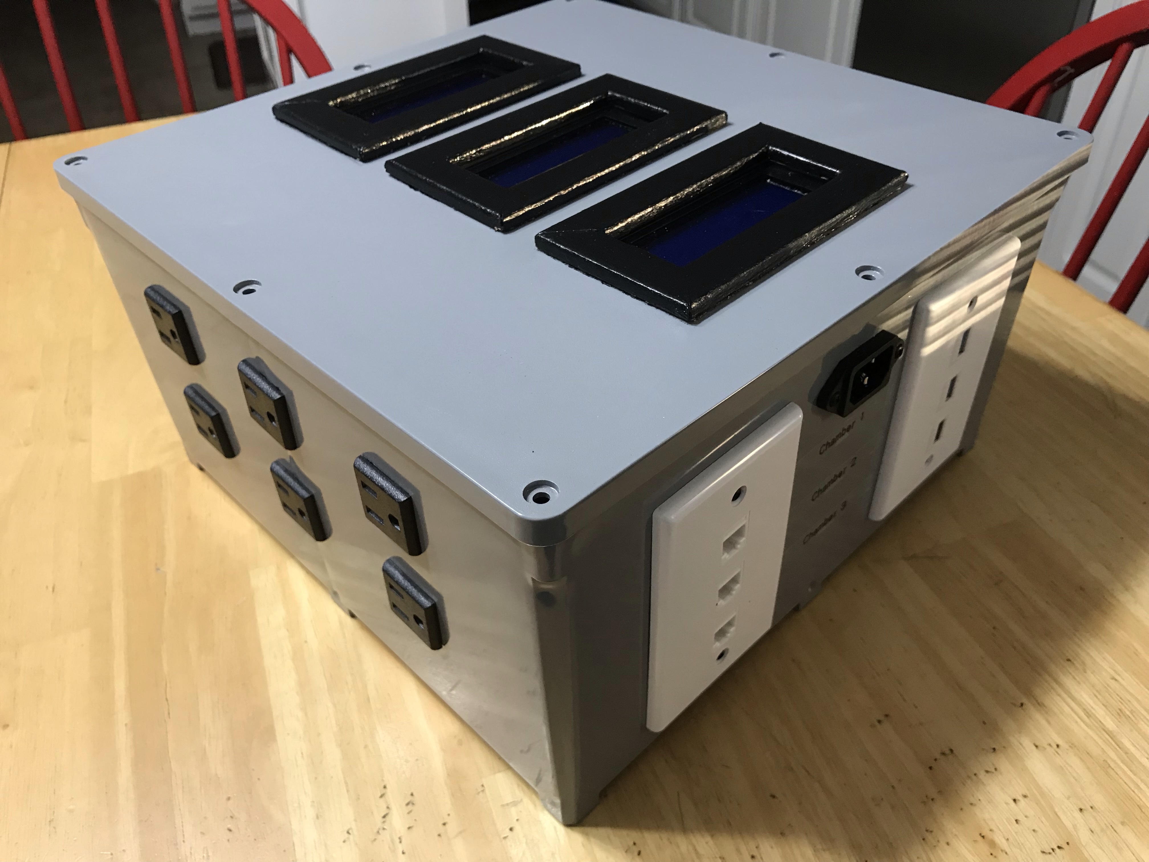
  9. Determine location of 3 Pin Inlet Power Plug Socket
  10. Cut opening to fit Socket
  11. Install Power Plug Socket
  12. Determine location of 3 Pin Power Socket Panel Receptacle AC125V 15A.
  13. Cut opening(s) to fit Receptacles
  14. Install Receptacles
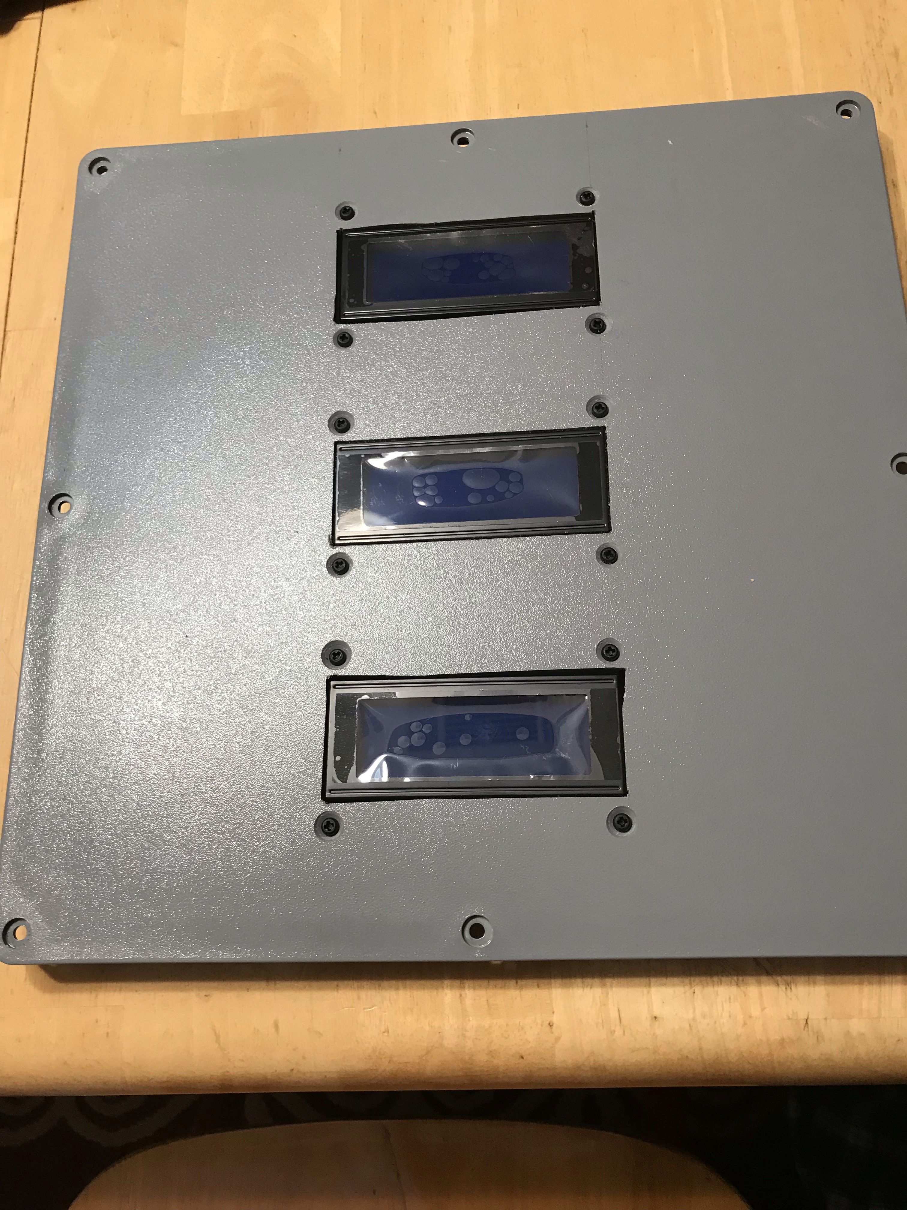
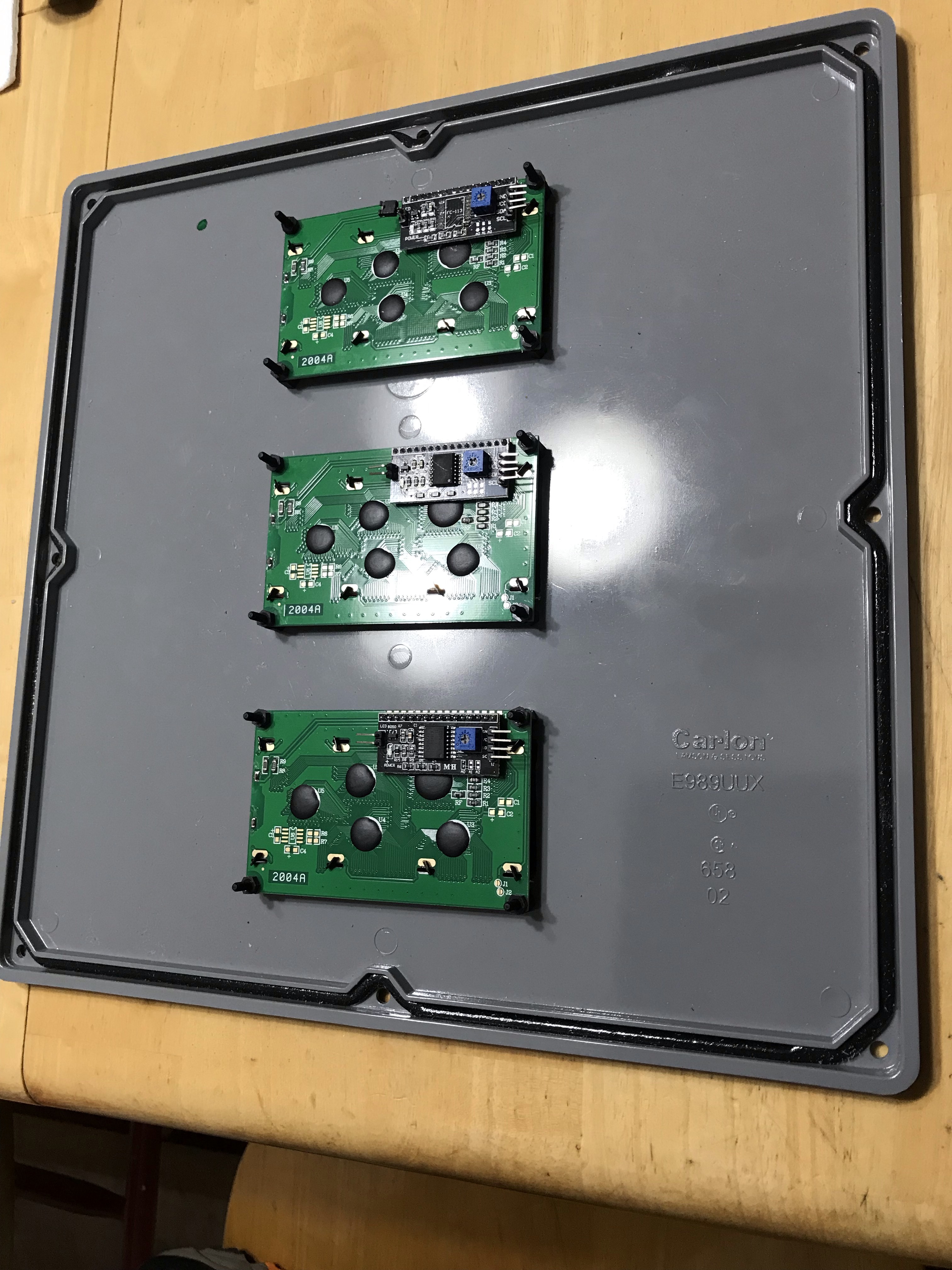
  15. Determine location of LCD Modules on the Project Box lid
  16. Cut openings to fit LCD Modules
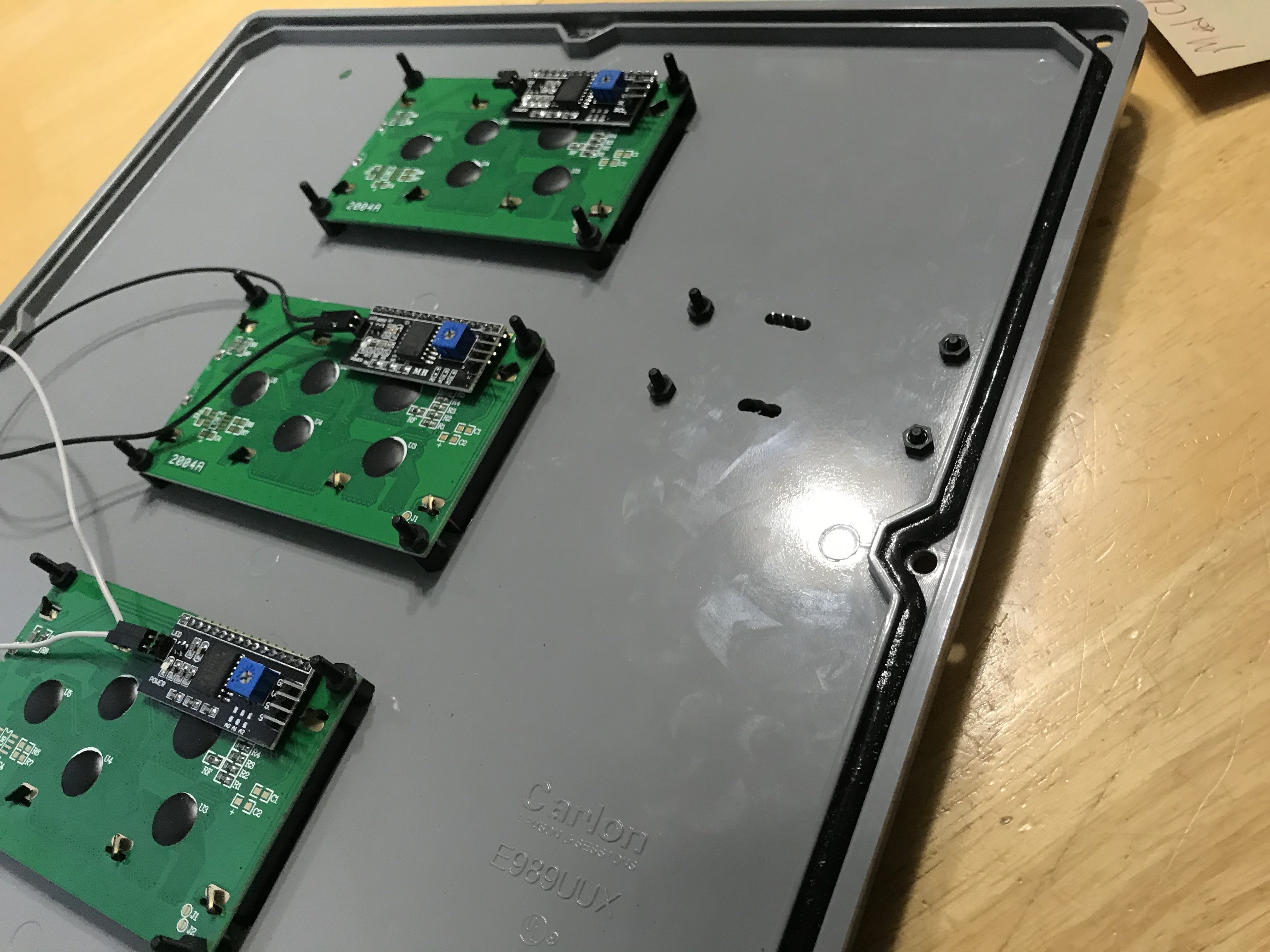
  17. Install LCD Modules to the Project Box lid
  18. Solder the following on the ESP8266 Breakout Board for BrewPi:
    1. 2-pin Screw Terminal Block
    2. RJ45 PCB Socket
    3. 1206 SMD 100uf Capacitor (to C1)
    4. 0805 SMD 4.7K Resistor (to R1)
    5. 0805 SMD 10K Resistor (to R2, R3, R4, R5)
    6. Mosfet SMD (to Q1, Q2)
    7. Male Pin Headers To LCD, Relay, and JP1 Contacts
    8. Female Pin Headers to contacts for the D1 Mini.
  19. Solder Male Pin Headers to the D1 Mini (make certain Male Pins point away from the D1 antenna)
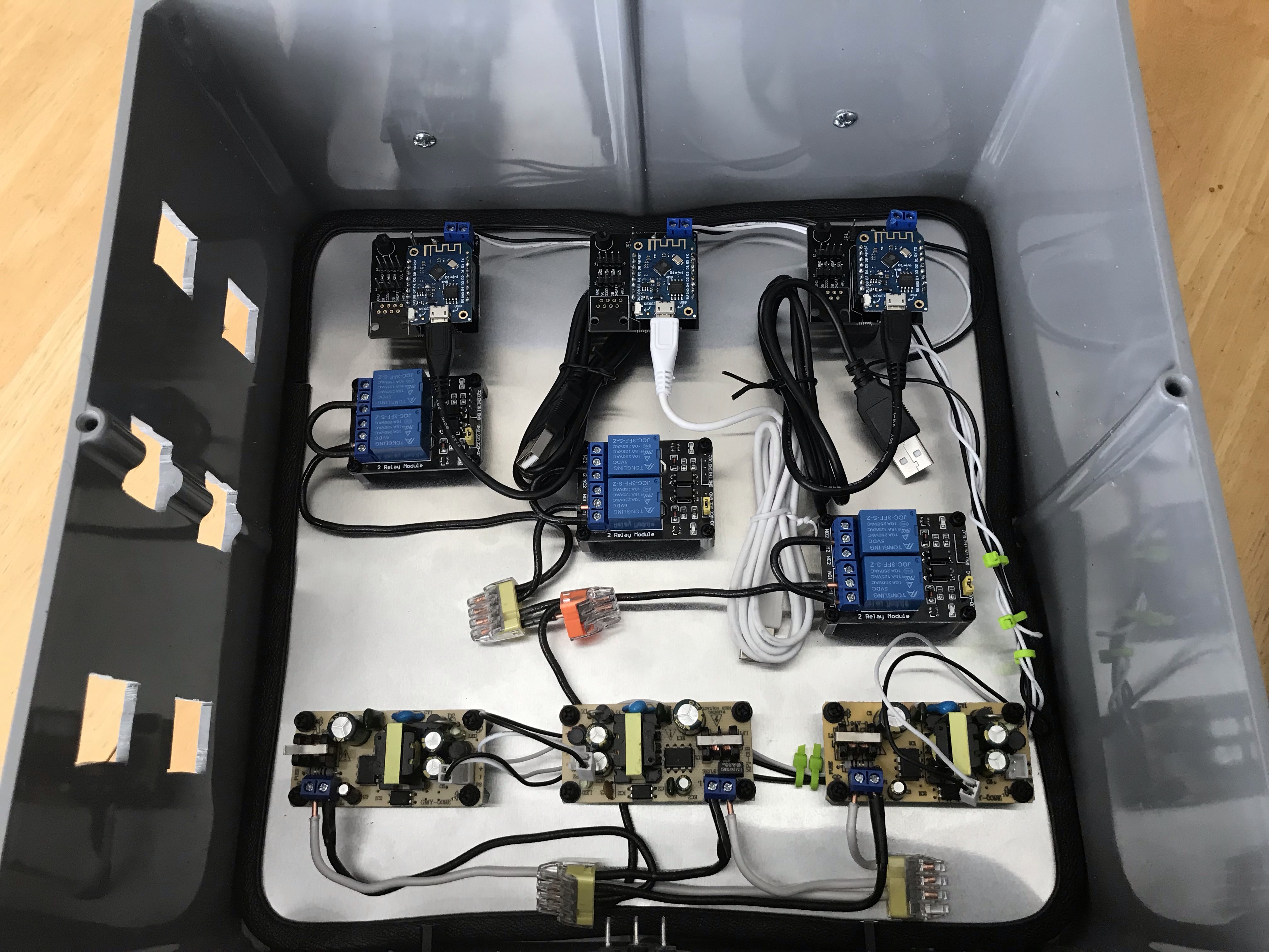
  20. Secure PS Module, Relay Module, and completed ESP8266 Breakout Board to the standoffs.
  21. Insert aluminum sub board with attached modules into the project box.
  22. Run Electrical wires appropriately (I referenced Thorrak’s how to site tinybat.ch to wire accordingly) from the Inlet Socket to the PS. From the PS to the ESP Breakout Board. From the Power Receptacles to the Relays, and all the points/connections in between.
  23. Install the USB and RJ45 Keystone Inserts into the Keystone Plate(s)
  24. Run Ethernet Patch Cable from RJ45 Keystone Insert to RJ45 Socket on the ESB Breakout Board.
  25. Connect D1 Mini to the ESB Breakout Board
  26. Run USB Patch Cord from USB Keystone Insert to D1 Mini.
  27. Connect Female to Female DuPont connectors appropriately from the ESB Breakout Board to the 2 Channel Relay.
  28. Connect Female to Female DuPont connectors appropriately from the ESB Breakout Board to the LCD Module.
Additional (optional) Steps
  1. Added handle to top of case
  2. Construct/install wood frame to trim around LCD Screen
  3. Ran Trim Lok edge trim around the Aluminum sub-boards (not only to protect skin and wires from getting cut, but if measured and cut properly, acts as a friction mount and holds the sub-boards in place to the project box)
  4. On the Power Supply Modules.
    1. Desoldered and removed inlet power connectors
    2. Soldered in more robust 2-Pin Screw Terminals
  5. Used Female DuPont connectors to open wire ends to connect PS to ESB Breakout Board.
  6. Used shims with the 3 Pin Receptacles to get a snugger fit
  7. Had to adjust LCD contrast using the potentiometer on the back of the LCD Screen
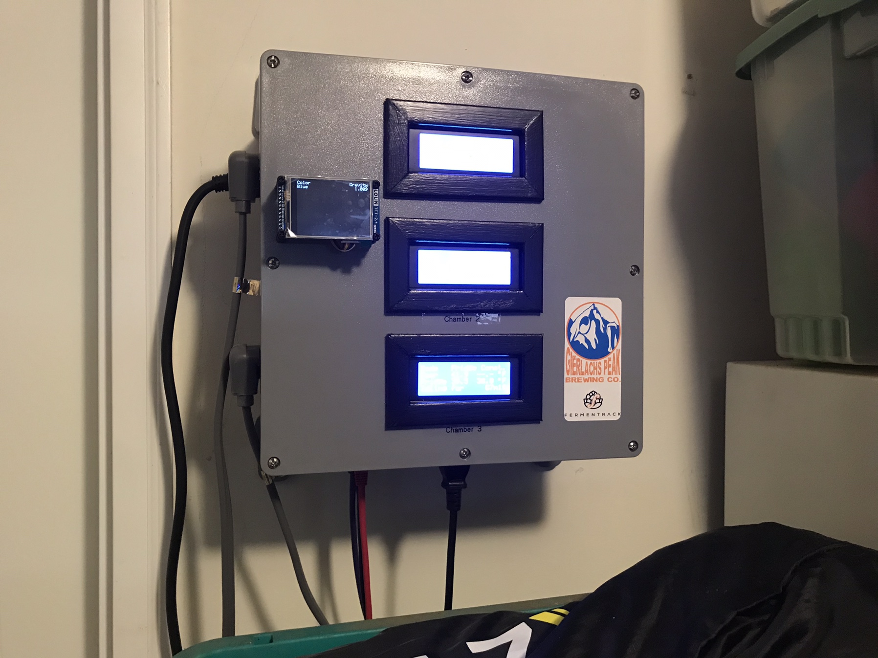
  8. Added labels to identify LCD Screens, Inputs, and Outputs.

3_1.jpg
3_3.jpg
3_6.jpg
3_7.jpg
3_8.jpg
3_10.jpg
3_11.jpg
3_13.jpg
3_15.jpg
3_17.jpg
 
Last edited:
Phase 4
Controller Flashing/Controller WiFi Connection Set-up/Adding a new Temp Controller

Make life easy on yourself and Flash your D1 Mini’s (or whatever approved device) through Fermentrack. My recommendation, flash the system test first. This will let you know if your wiring, probes, and general set-up is in working order. Once the test is complete, flash with the appropriate version of BrewPi.

The next step is to connect your D1 Mini (or whatever Approved device) to your network. I feel like a heel, but this step stymied me. When you first power up your D1 Mini (either through USB or 5v PS) it will broadcast an Access Point (AP) for about 5 minutes. During this 5 minutes, you want to use your smart phone, tablet, computer, or whatever you have to connect to the AP. When you connect, you will set the WiFi. Locate your network SSID, type in the network password, and connect. You’re D1 Mini is now connected to your network and you can work through Fermentrack to add a new temp controller.
 
Phase 5
Tilt Bridge Installation

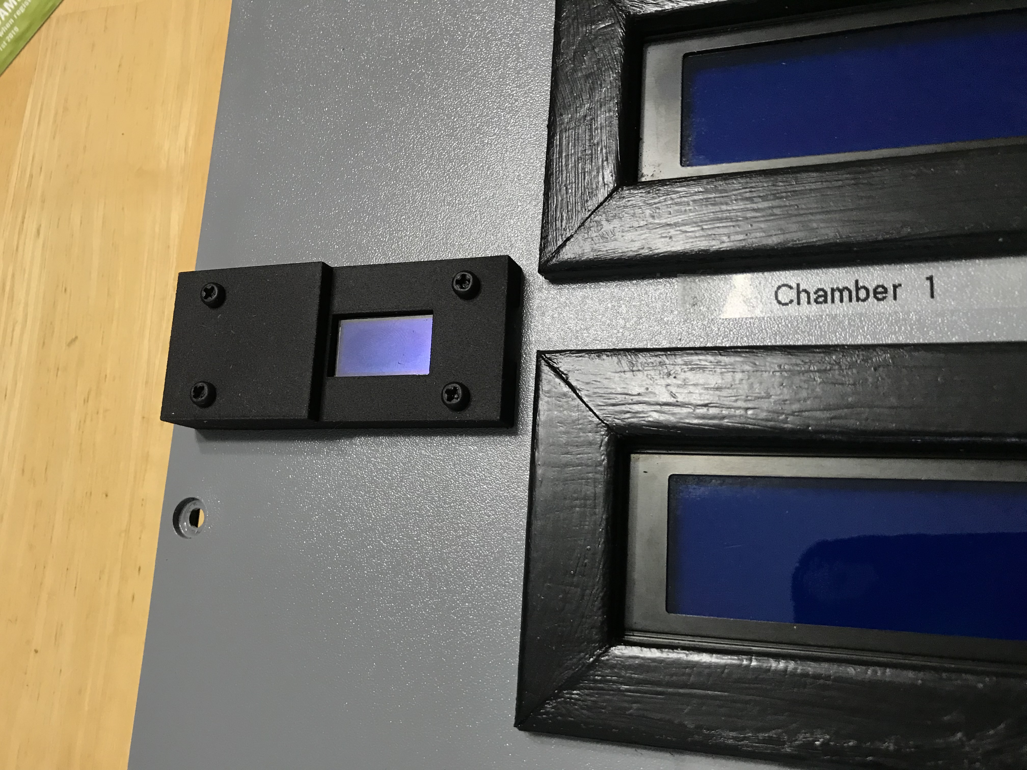
As I was coming to a close with my Fermentrack Build, the Tilt Bridge Project was announced. I currently do not have a Tilt Hydrometer, but I know that will change in the future. The toughest part of the install was designing an enclosure. I taught myself how to use OpenSCAD and designed my enclosure. After bouncing some design ideas off of Thorrak, I decided to move forward and have a design printed using shapeways.com.

B.O.M.
  • M3 Nylon Screws and Nuts (Micro Center)
  • ESP32 OLED Wemos WiFi Module+ Bluetooth Dual ESP-32 ESP-32S ESP8266 OLED For Arduino (Ali Express)
  • Female to Female DuPont Connectors (Ali Express)
  • Male Pin Header (Ali Express)
  • Custom 3D printed ESP32 Surface Mount Enclosure (shapeways.com)
  1. Design ESP32 enclosure
  2. 3D print the design
  3. Flash ESP32 with Tilt Bridge **
  4. Solder male header pins onto the 3V, Gnd, Gnd, 5V locations on the ESP32.
  5. Place ESP32 into the enclosure, centering the OLED with the enclosures OLED window.
  6. Mark locations of the ESP32 mounting holes on the enclosure.
  7. Drill pilot holes on the marks and expand holes to allow the nylon screws to go through.
  8. Push nylon screws through the enclosure and through the ESP32 mounting holes.
  9. Position enclosure.
  10. Mark where nylon screws contact the surface.
  11. Mark where the male header pins contact the surface.
  12. Drill pilot holes on the surface marks where the screws contacted, and expand holes to allow nylon screws to go through.
  13. Drill pilot holes on the male pin marks, and expand if necessary.
  14. Mount ESP32 with enclosure to the surface using nylon screws and nuts to secure ESP32.
  15. Remove 1 Female DuPont terminus from 2 DuPont wires.
  16. Run 5v and Gnd wires from PS to ESP32 accordingly.

**when flashing the ESP32, please use Thorrak’s tutorials/references as your guide.


www.tiltbridge.com
docs.tiltbridge.com/en/master

Couple of things I picked up along the way...

When flashing, if Fermentrack doesn’t see the ESP32 when in serial mode, there’s a good chance the USB cable is at fault. If you are using a charging cable, this will happen. You will need to find a USB cable that is for Data transfer.

Once I started to use the correct cable, my flashing would timeout and Tilt Bridge would not flash onto the ESP32. I found that there can be an issue where an RPi and the USB to UART Bridge on the ESP32 will not communicate and allow flashing to occur. To get past this, I held down the ‘boot’ button on the ESP32 while flashing to install the Tilt Bridge.

56582E19-D8F7-4F98-AA9F-7B1DB787E2CD.jpeg
BEEF9ABF-A33F-4B0E-9F15-540F41AB5B1B.jpeg
026CA9EB-717F-4EF2-8811-918FE62D0841.jpeg
366A251B-636C-463C-9A15-4E12EC436772.jpeg
 
I can't believe I never saw this build thread until now. I'm still in awe of how clean this looks. Great work!!

Thanks!

In all seriousness though, it’s your vision. I just followed your directions and asked questions when I needed help. So, thank you for putting together this awesome tool and help coach me up when needed so I could create the Fermentrack Build that works for me.

I have my 6th Fermentrack batch in the chamber now, and I still stare at the graphs in awe.

Hopefully the build page can help/has helped some fellow home brewers. I know, I love build threads....SWMBO...not so much.
 
Thanks a lot for this (how to do)

That was the last missing information before starting this project.

Everything is so details and clean and the shopping list is spot on for AliExpress.
 
Phase 5 **REVISED**
Tilt Bridge Installation

TiltBridge is moving on to a new iteration. This new version looks nicer and hopefully others will have more uniform success with the build utilizing some new components.

At the time of this writing the new firmware is not available, but once available, you’ll be able to flash your new device either through Fermentrack or through esptool.

B.O.M.
M3 Nylon Screws and Nuts (Micro Center)
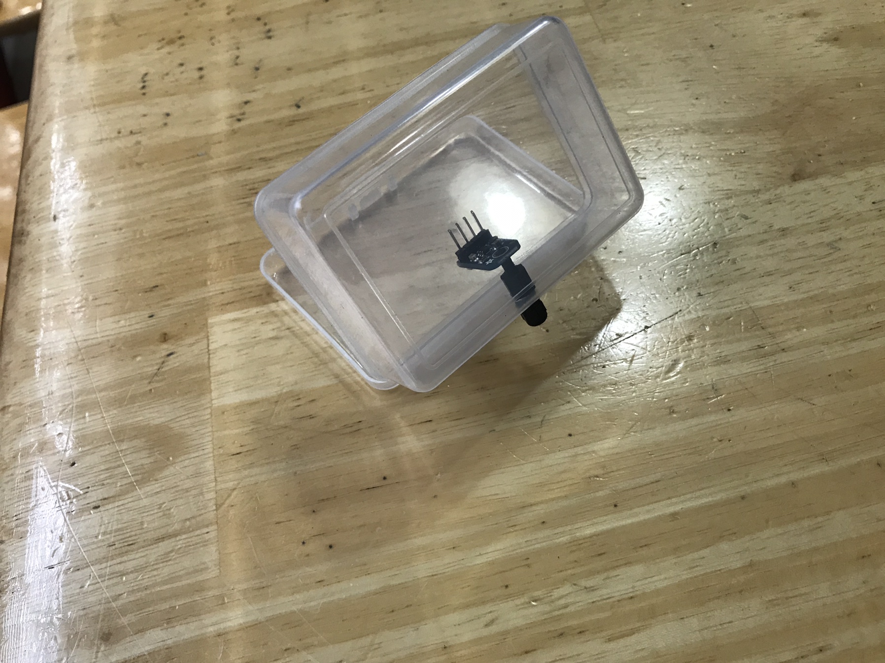
Lolin D32 Pro v2.0 (Ali Express)
Lolin TFT 2.4 Touch Screen (Ali Express)
20cm TFT ePaper Cable (Ali Express)
3.3V LDO Buck Converter (Micro Center)
Female to Female DuPont Connectors (Ali Express)
Male Pin Header (Ali Express)
Small Project Box (Ali Express)
Grommets (Micro Center)
Custom 3D printed Surface Mount Enclosure (shapeways.com)

Design D32 Pro enclosure
3D print the design
Flash D32 Pro with Tilt Bridge **
Solder male header pins onto the 3V, Gnd, Gnd, and EN locations on the D32 Pro.
Solder male header pins onto the GND, 3V, Vin, and EN locations on the Buck Converter.
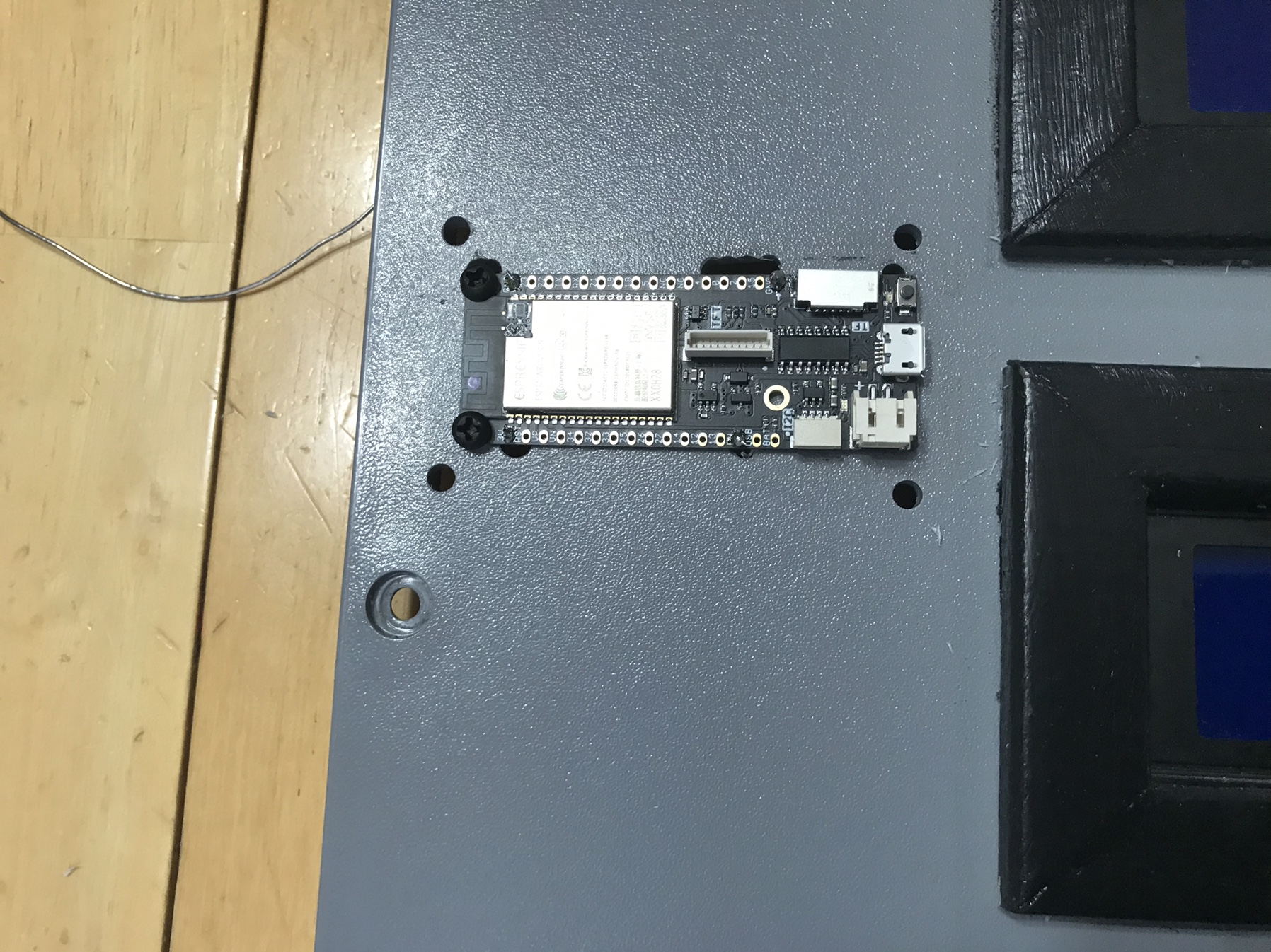
Drill 3 holes into the Small Project Box. One to allow for mounting of the Buck Converter and the other two to allow wires in and out. (I used the case that the TFT 2.4 came packaged in as my project box)
Place grommets into the holes where the wires will pass.
From the 5V Power Source. Run a hot wire from the PS to Vin on the Buck Converter.
From the 5V Power Source. Run a ground wire from the PS to GND on the Buck Converter.
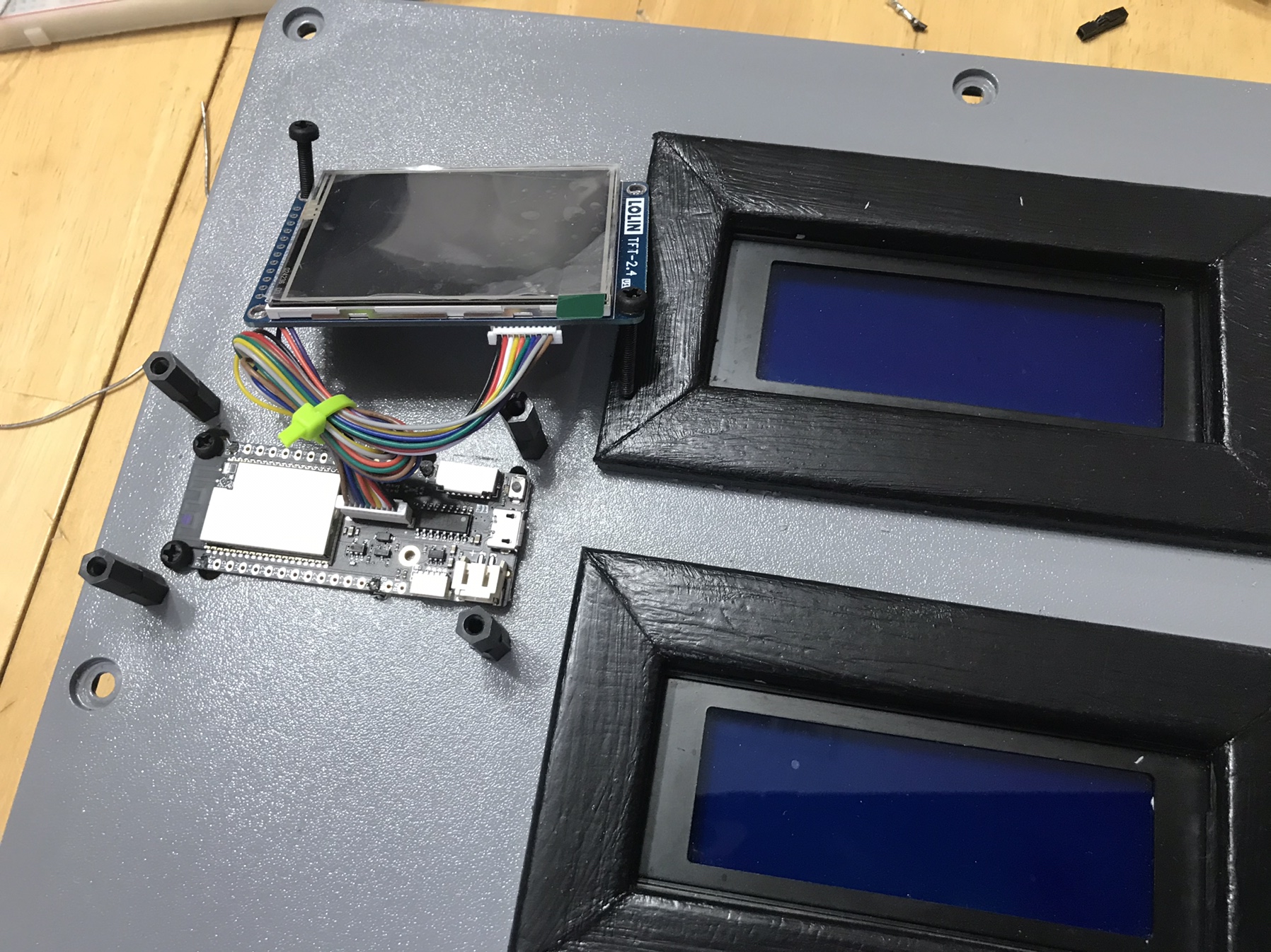
Mark locations of the D32 Pro mounting holes on the surface.
Mark locations of the D32 Pro Header Pins on the surface.
Drill pilot holes on the marks and expand holes to allow the nylon screws or Female DuPont Connectors to go through.
Mark locations of the TFT 2.4 mounting holes on the surface.
Drill pilot holes on the marks and expend holes to allow nylon screws to go through.
Push nylon screws through the D32 Pro mounting holes and fasten the the surface.
With Female to Female DuPont connectors, jump the EN to GND on the D32 Pro.
Connect the D32 Pro to the TFT 2.4 with the TFT ePaper Cable.
Push nylon screws through the TFT 2.4 mounting holes, and fasten to the surface.
From the Buck Converter. Run a hot wire from 3V on the BC to 3V on the D32 Pro.
From the Buck Converter. Run a ground wire from GND on the BC to GND on the D32 Pro.

Additional Notes:
The Buck Converter project box was attached to an inside wall of the Fermentrack control box with double sided Very High Bond (VHB) tape.
I bored out the mounting holes on the Buck Converter, D32 Pro and TFT 2.4 from 2mm to 3mm using a tapered file.


**when flashing the D32 Pro, please use Thorrak’s tutorials/references as your guide.


www.tiltbridge.com
docs.tiltbridge.com/en/master

IMG_1554.JPG


IMG_1555.JPG


IMG_1556.JPG


IMG_1557.JPG


IMG_1558.JPG


IMG_1559.JPG


IMG_1560.JPG


IMG_1561.JPG


IMG_1562.JPG


IMG_1563.JPG
 
Last edited:
Phase 2
RJ45 Breakout Board Control Box Build

Ultimately, I want to close up my fermentation control box and forget about it. I don’t want to go in and connect USB cables to my D1 Mini or if a temp probe goes bad, have to open up, rewire, and swap-out probes.

Since the PCB is called an RJ45 Sensor Breakout, I thought I would create an RJ45 Breakout Board Control Box. I would run three (3) pairs of DS18B20 Temperature Probes into one project box. The project box would contain three (3) RJ45 Sensor Breakout PCBs. A pair of probes would be connected to an RJ45 Sensor Breakout PCB. An Ethernet cable (x3) would connect an RJ45 Sensor Breakout Board to the Main Control Box.
  1. Purchase a project box that is large enough to comfortably hold as many RJ45 Sensor Breakout PCBs as desired
  2. Cut a piece of Aluminum to fit inside project box to act as a sub-board.
  3. Place PCBs on aluminum and mark mounting hole locations.
  4. Drill holes in aluminum where mounting holes were marked.
  5. Add standoffs to mounting holes.
  6. Drill hole(s) large enough to allow 2 temperature probes/hole through.
  7. Install grommets onto the holes
  8. On opposite side of the temperature probes, drill pilot holes lining up with RJ45 Jack on PCBs.
  9. Using pilot holes as a guide, cut opening to fit RJ45 Socket.
  10. On the DS18B20 probes, add Female DuPont connectors to the exposed wire ends.
  11. Solder the following on the RJ45 Sensor Breakout PC
    1. RJ45 PCB Socket
    2. 2-pin Screw Terminal Block
    3. Male Pin Headers to the Data, 3v3, and Gnd locations on the PCB
  12. Secure completed RJ45 PCBs to the standoffs.
  13. Insert aluminum sub-board with RJ45 PCB(s) into project box
  14. Thread DS18B20 Wire ends through the grommets
  15. Attach DS18B20s to the appropriate Data, 3v3, and Gnd location on the PCBs
  16. Close the project box
  17. Connect Ethernet patch cables to the RJ45 sockets.
  18. Run Ethernet patch cables to the main control box.
View attachment 623545

View attachment 623546

View attachment 623547

View attachment 623548

View attachment 623549

View attachment 623550


View attachment 623552
View attachment 623553
Great build layout, but I am puzzled about the two blue screw terminals on the breakout boards. Can you enlighten me as for their use.
 
private4587 said:
Great build layout, but I am puzzled about the two blue screw terminals on the breakout boards. Can you enlighten me as for their use.

Not needed! They are for setting up a door alarm. I’ll be honest, I’m not even certain if it’s configurable yet with Fermentrack. Since I was soldering, I decided to put them in, so if I wanted, I could easily add them.
 
Not needed! They are for setting up a door alarm. I’ll be honest, I’m not even certain if it’s configurable yet with Fermentrack. Since I was soldering, I decided to put them in, so if I wanted, I could easily add them.
^^ This. It’s the same as the two jumper pins as well - it’s so you can choose which (if either) to use.

I don’t use door sensors on any of my builds but support does exist in the ESP8266 port of the BrewPi firmware.
 
^^ This. It’s the same as the two jumper pins as well - it’s so you can choose which (if either) to use.

I don’t use door sensors on any of my builds but support does exist in the ESP8266 port of the BrewPi firmware.
Thanks gents for cleave clearing that up for me. Thorrack could please supply link where i could get these tow boards and the RJ45 connectors. Also i can see how they are connected to breakout board but how does the connection in the main board differentiate with the wiring in the lan cable? hope that makes sense.
 
private4587 said:
Thanks gents for cleave clearing that up for me. Thorrack could please supply link where i could get these tow boards and the RJ45 connectors. Also i can see how they are connected to breakout board but how does the connection in the main board differentiate with the wiring in the lan cable? hope that makes sense.

The current Thorrak boards available and the two used in my build can be found here:

https://www.pcbs.io/search?query=Thorrak

As far as how the boards differentiate, well the two boards in my build work together. The RJ45 breakout board can take the signal from 3 Temperature Sensors (I only use 2) and get the signals into the RJ45 Jack. Then using an Ethernet Patch Cable, I can run the signal from my breakout board to my controller PCB which of course has another RJ45 Jack on it.

From there the signals are split (don’t ask me technical terms) and allows the BrewPi and Fermentrack Magic (<-that is a technical term) to happen.

The thing is....you don’t have to use the RJ45s. You can use RJ11s (which is phone cable). You could search around and find PCB’s designed by someone else that allows you to take the Temp Sensor straight to the main PCB. You just need to decide what you need to control and how you want it to look...and then go from there.
 
Last edited:
Thanks gents for cleave clearing that up for me. Thorrack could please supply link where i could get these tow boards and the RJ45 connectors. Also i can see how they are connected to breakout board but how does the connection in the main board differentiate with the wiring in the lan cable? hope that makes sense.

Sure, it’s covered here in the documentation.
 
Phase 2
RJ45 Breakout Board Control Box Build

Ultimately, I want to close up my fermentation control box and forget about it. I don’t want to go in and connect USB cables to my D1 Mini or if a temp probe goes bad, have to open up, rewire, and swap-out probes.

Since the PCB is called an RJ45 Sensor Breakout, I thought I would create an RJ45 Breakout Board Control Box. I would run three (3) pairs of DS18B20 Temperature Probes into one project box. The project box would contain three (3) RJ45 Sensor Breakout PCBs. A pair of probes would be connected to an RJ45 Sensor Breakout PCB. An Ethernet cable (x3) would connect an RJ45 Sensor Breakout Board to the Main Control Box.
  1. Purchase a project box that is large enough to comfortably hold as many RJ45 Sensor Breakout PCBs as desired
  2. Cut a piece of Aluminum to fit inside project box to act as a sub-board.
  3. Place PCBs on aluminum and mark mounting hole locations.
  4. Drill holes in aluminum where mounting holes were marked.
  5. Add standoffs to mounting holes.
  6. Drill hole(s) large enough to allow 2 temperature probes/hole through.
  7. Install grommets onto the holes
  8. On opposite side of the temperature probes, drill pilot holes lining up with RJ45 Jack on PCBs.
  9. Using pilot holes as a guide, cut opening to fit RJ45 Socket.
  10. On the DS18B20 probes, add Female DuPont connectors to the exposed wire ends.
  11. Solder the following on the RJ45 Sensor Breakout PC
    1. RJ45 PCB Socket
    2. 2-pin Screw Terminal Block
    3. Male Pin Headers to the Data, 3v3, and Gnd locations on the PCB
  12. Secure completed RJ45 PCBs to the standoffs.
  13. Insert aluminum sub-board with RJ45 PCB(s) into project box
  14. Thread DS18B20 Wire ends through the grommets
  15. Attach DS18B20s to the appropriate Data, 3v3, and Gnd location on the PCBs
  16. Close the project box
  17. Connect Ethernet patch cables to the RJ45 sockets.
  18. Run Ethernet patch cables to the main control box.
View attachment 623545

View attachment 623546

View attachment 623547

View attachment 623548

View attachment 623549

View attachment 623550


View attachment 623552
View attachment 623553
Hi Garzlok really like your build instructions, could you explain how the RJ45 wiring is setup using two temp probes like you have in your build going to one breakout board. The reason I am asking as I want the board to inside fermenter fridge and thus need run lan cable into fridge first and the connect the RJ45 plug.
 
First, for my DS18B20 temperature sensor, the leads are as follows:
Red=3v3
Yellow=Data
Black=Ground

I attached Female DuPont connectors to the end of the leads. (I choose to do this in case I had issues with my probes and needed to swap them out)

On the RJ45 breakout board I soldered on the RJ45 Jack and Male header pins.

I then attached the appropriate sensor lead to the corresponding header pin. (It does not matter which row of pins you decide to use)

I then run an Ethernet patch cable from the RJ45 breakout board to the RJ45 Jack on my main PCB.
Hi garzlok yes I can understand how you connected to the board but my question is how does the controller know which sensor is which if I wire the RJ45 male plug in the standard lan setup
 
Hi garzlok yes I can understand how you connected to the board but my question is how does the controller know which sensor is which if I wire the RJ45 male plug in the standard lan setup

Each DS18B20 has a unique “address” assigned to it by the manufacturer. When you hook them up to your controller, the controller sees each of the addresses. Then, in Fermentrack, you tell the controller “the sensor with address A is the fridge sensor, the sensor with address B is the beer sensor”, etc. You’ll have to do some trial and error to discern which address corresponds to which sensor, but it is pretty easy to determine with a few minutes and a glass of ice water.
 
Each DS18B20 has a unique “address” assigned to it by the manufacturer. When you hook them up to your controller, the controller sees each of the addresses. Then, in Fermentrack, you tell the controller “the sensor with address A is the fridge sensor, the sensor with address B is the beer sensor”, etc. You’ll have to do some trial and error to discern which address corresponds to which sensor, but it is pretty easy to determine with a few minutes and a glass of ice water.
Many thanks I think I will add a glass or two of beer to go with the water and ice. Awaiting AliExpress now
 
Phase 1
Raspberry Pi Set-Up/Fermentrack Installation

This was my first experience with anything RaspberryPi. I decided to install the Lite Version of the Raspbian OS (Stretch). Though I experienced no issues, I found myself later wishing I had installed the full version. If you are new to RaspberryPi, my recommendation is to use the full version. The full version has a nifty backup app preinstalled, SD Card Copier (which I eventually installed) and a GUI (which I eventually installed).

The ability to complete easy backups is a necessity. Though I have yet to experience an SD Card failure, reading through these forums, SD Card failure appears to be inevitable. Make backing up as easy as possible on yourself!

For a reason I did not expect, I found a need for a GUI. RaspberryPi/Fermentrack work off a Home Network. I travel...I travel a lot, and I had no plans to set-up port forwarding and blow holes through my network security just so I can geek-out over a fermentation process. Then I learned about VNC Viewer and Remot3.it. In a nutshell VNC allows me to both locally and remotely connect to my RapberryPi. Remot3 allows me to access Fermentrack from a remote location. Both are secure services that are worth investigating if you feel the need.

The catch? If you want to use the Free.99 Home Version of VNC Viewer, your RaspberryPi has to have a GUI and cannot be headless. If you are willing to pay for the Enterprise Version of the VNC viewer, than you can have a headless version of Raspbian. Me? Add the GUI and go the Free route.
Hi Garzlok very interested in this remote setup do you have any layman instructions for setup and running of the two programmes you used Thanks
 
First thing you’ll need to do is to make sure VNC is enabled in your RaspberryPi Configuration.

You then will need a VNC viewer on whatever device you want to use to connect remotely to your RPi.

For Remote.it instructions, follow along here: Brewpiremix initial setup help
 
@garzlok super impressed and inspired by your work! Thanks for sharing!!

I do have a question for you. As I was reviewing your controller, something stood out as a potential limitation. In theory, your controller has a 20amp limit at best and on most 110v outlets it would be 15amp. I would think that is low if you have 3 brews fermenting at the same time and you have hot and cold elements hooked up for each brew. Have you tested this by having all 6 of your outlets utilized at the same time?
 
Luckily, all 6 outlets will not get used at the same time.

If there’s a call to cool, the heat will not be on, so only 3 outlets can be on at one time.

The largest draw I have is a full refrigerator that pulls 3.8A max. My Fermentation Coolers pull 1.1A each, so if all my coolers are running at the same time, I’m only pulling 6 amps putting me only at 40% capacity.

For heating, I use simple 40watt at @115V heating wraps, so that’s less than half an Amp each.

I feel pretty good with my equipment a 15A circuit is more than adequate.
 
Sorry to drag up an old thread, but I have been using this excellent thread (thanks @garzlok ) to try to piece together my own Fermentrack build. I purchased similar power modules from AliExpress:

20200713_104724.jpg


My question concerns the connectors outlined in red. The left one is for 120V coming in, the right one for 5V going out. I have no idea what type of connectors these are? There are two holes below the 120V connector that I can install a screw terminal, although taking the existing one out will be a challenge for my sad desoldering skills. lol

I am not sure, however, what to do with the 5v connector. Dupont cables fit on the pins. Would these be ok to carry the 5V to the Thorrak board? Does anyone know what type of connectors these are and can they be found online? (Preferably Amazon as the 70-80 day shipping from AliExpress is tough to take )

Thanks for any help

Paul
 
Glad it’s helped you Paul. Though it’s kinda buried, I did write-up the process I completed on my build to address your question.

Additional (optional) Steps
....
  1. On the Power Supply Modules.
    1. Desoldered and removed inlet power connectors
    2. Soldered in more robust 2-Pin Screw Terminals
  2. Used Female DuPont connectors to open wire ends to connect PS to PCB Breakout Board.
The screw terminals allow you to use a heftier gauge wire that can handle the 120V and in my case 15A going into the PSU.

I also have very minimal soldering skills, but I promise, desoldering that part from the component and then soldering in the screw terminals is not that difficult.
 
Last edited:
Glad it’s helped you Paul. Though it’s kinda buried, I did write-up the process I completed on my build to address your question.

Additional (optional) Steps
....
  1. On the Power Supply Modules.
    1. Desoldered and removed inlet power connectors
    2. Soldered in more robust 2-Pin Screw Terminals
  2. Used Female DuPont connectors to open wire ends to connect PS to PCB Breakout Board.
The screw terminals allow you to use a heftier gauge wire that can handle the 120V and in my case 15A going into the PSU.

I also have very minimal soldering skills, but I promise, desoldering that part from the component and then soldering in the screw terminals is not that difficult.

Thanks so much. Yes I did miss that. I guess I should read more carefully instead of just looking at the great pictures lol.

Thanks again for a great write up
 
No worries.

Looking back at the pictures. I did use some kind of female connector to the 5V (Load and Neutral) Out from the PSU. For the life of me, I don't remember what I used, but I would have picked it up from my local MicroCenter or Frys. If memory serves me correctly, I was not completely happy with the Female DuPont Connector and it felt like a loose connection.

EDIT: I used something similar to the female connector pictured here. This picture was found on Amazon searching for 2 pin connectors. Again, this is just a representation of the connector I used to attach to the 5V 2A Out of my PSU.

1594665303334.png
 
Last edited:
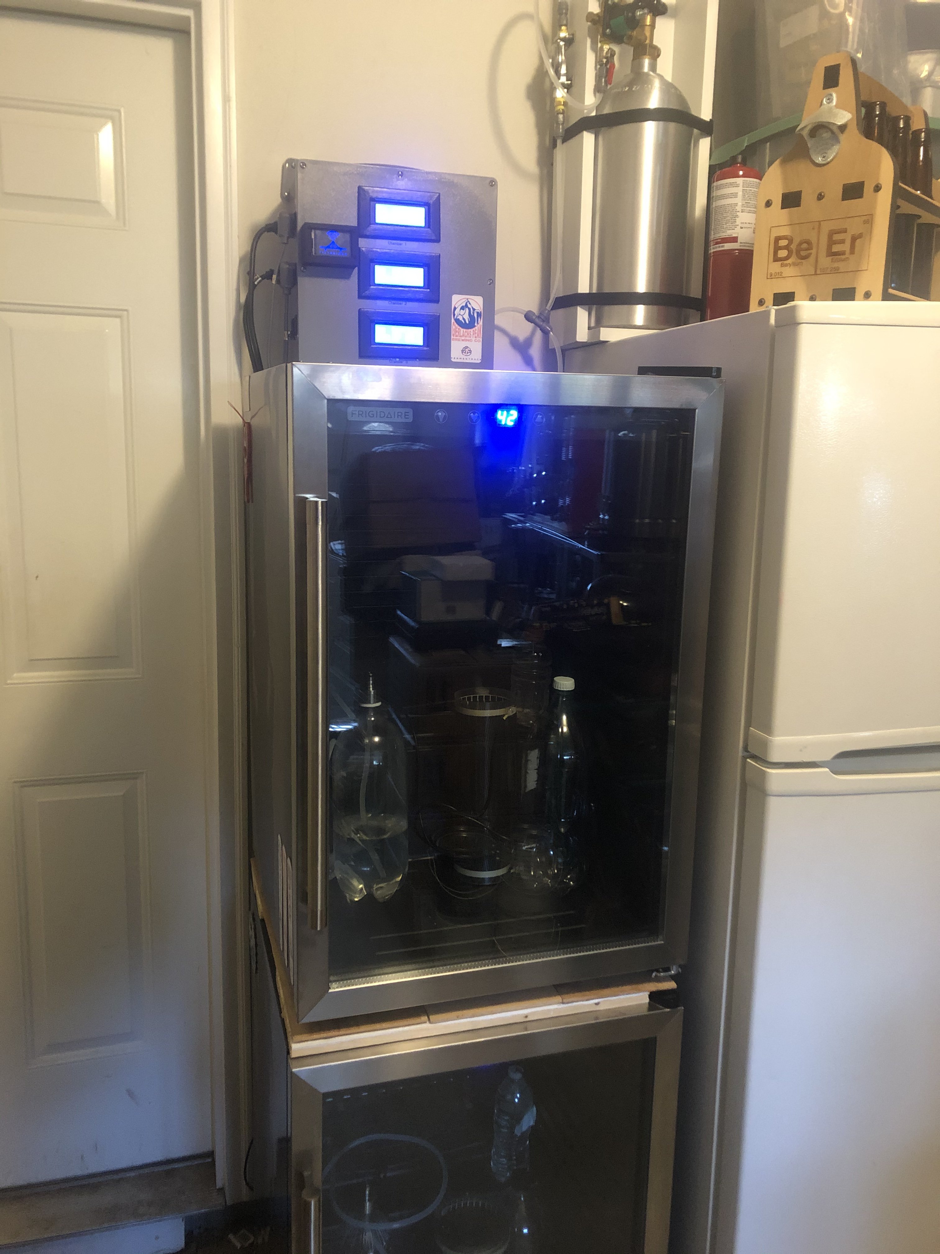
Well, it only took me 15 months and I don’t want to look at the receipts, but my system for fermentation control is “done”.

I actually had to go in and swap out a bad relay and trouble shoot some LCD issues, and I’m happy to say, it was a pretty easy process with the spacing of the build. (I even swapped out an LCD)

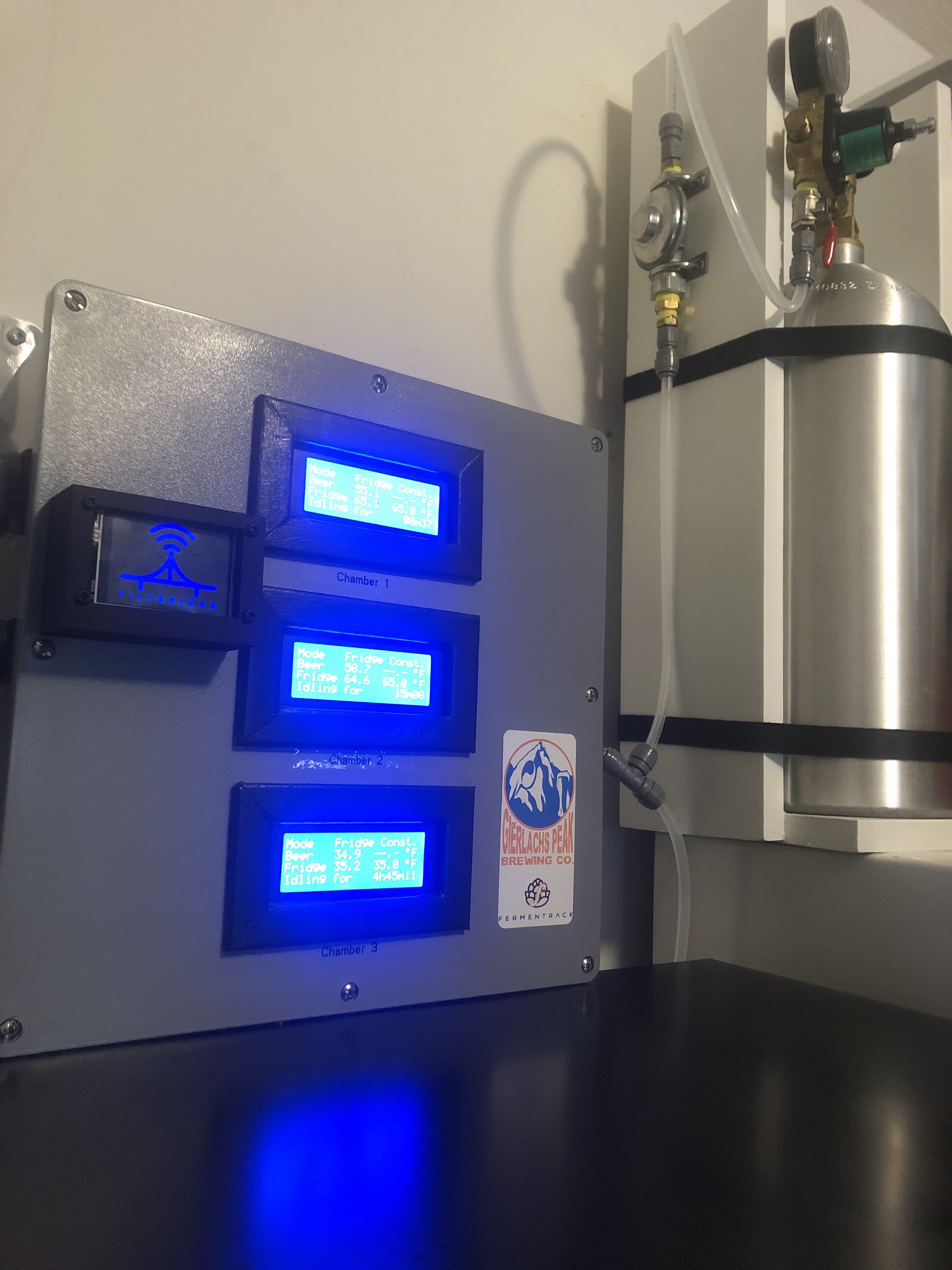
Not only can I hold fermentation to about 0.2F of my target temp (thanks @Thorrak ), but I can deliver and hold CO2 pressure in my Brew Buckets at 0.5PSI without worry of explosion, implosion or O2 ingress (Thanks @day_trippr ). I can also harvest CO2 and purge my kegs of O2 before filling.

624DF2F3-86FC-4E9E-AC83-A5ACD2671BC5.jpeg
7C927FF4-B273-45E0-8B78-735FD437E12A.jpeg
 
Phase 5
Tilt Bridge Installation

As I was coming to a close with my Fermentrack Build, the Tilt Bridge Project was announced. I currently do not have a Tilt Hydrometer, but I know that will change in the future. The toughest part of the install was designing an enclosure. I taught myself how to use OpenSCAD and designed my enclosure. After bouncing some design ideas off of Thorrak, I decided to move forward and have a design printed using shapeways.com.

B.O.M.
  • M3 Nylon Screws and Nuts (Micro Center)
  • ESP32 OLED Wemos WiFi Module+ Bluetooth Dual ESP-32 ESP-32S ESP8266 OLED For Arduino (Ali Express)
  • Female to Female DuPont Connectors (Ali Express)
  • Male Pin Header (Ali Express)
  • Custom 3D printed ESP32 Surface Mount Enclosure (shapeways.com)
  1. Design ESP32 enclosure
  2. 3D print the design
  3. Flash ESP32 with Tilt Bridge **
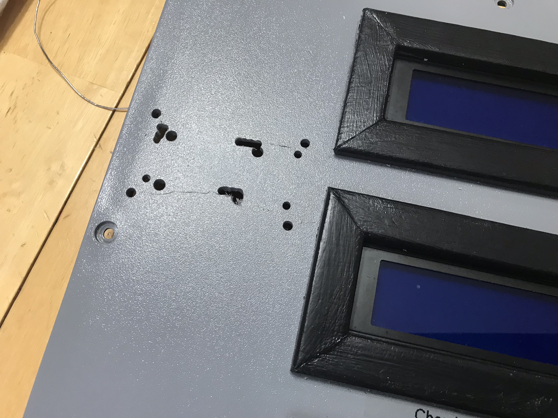
  4. Solder male header pins onto the 3V, Gnd, Gnd, 5V locations on the ESP32.
  5. Place ESP32 into the enclosure, centering the OLED with the enclosures OLED window.
  6. Mark locations of the ESP32 mounting holes on the enclosure.
  7. Drill pilot holes on the marks and expand holes to allow the nylon screws to go through.
  8. Push nylon screws through the enclosure and through the ESP32 mounting holes.
  9. Position enclosure.
  10. Mark where nylon screws contact the surface.
  11. Mark where the male header pins contact the surface.
  12. Drill pilot holes on the surface marks where the screws contacted, and expand holes to allow nylon screws to go through.
  13. Drill pilot holes on the male pin marks, and expand if necessary.
  14. Mount ESP32 with enclosure to the surface using nylon screws and nuts to secure ESP32.
  15. Remove 1 Female DuPont terminus from 2 DuPont wires.
  16. Run 5v and Gnd wires from PS to ESP32 accordingly.

**when flashing the ESP32, please use Thorrak’s tutorials/references as your guide.


www.tiltbridge.com
docs.tiltbridge.com/en/master

Couple of things I picked up along the way...

When flashing, if Fermentrack doesn’t see the ESP32 when in serial mode, there’s a good chance the USB cable is at fault. If you are using a charging cable, this will happen. You will need to find a USB cable that is for Data transfer.

Once I started to use the correct cable, my flashing would timeout and Tilt Bridge would not flash onto the ESP32. I found that there can be an issue where an RPi and the USB to UART Bridge on the ESP32 will not communicate and allow flashing to occur. To get past this, I held down the ‘boot’ button on the ESP32 while flashing to install the Tilt Bridge.

View attachment 627862 View attachment 627863 View attachment 627864 View attachment 627865

I don't suppose you would share or sell your Custom 3D printed ESP32 Surface Mount Enclosure?

I am looking to make the same 3 fermenter setup.
 
Phase 2
RJ45 Breakout Board Control Box Build

Ultimately, I want to close up my fermentation control box and forget about it. I don’t want to go in and connect USB cables to my D1 Mini or if a temp probe goes bad, have to open up, rewire, and swap-out probes.

Since the PCB is called an RJ45 Sensor Breakout, I thought I would create an RJ45 Breakout Board Control Box. I would run three (3) pairs of DS18B20 Temperature Probes into one project box. The project box would contain three (3) RJ45 Sensor Breakout PCBs. A pair of probes would be connected to an RJ45 Sensor Breakout PCB. An Ethernet cable (x3) would connect an RJ45 Sensor Breakout Board to the Main Control Box.
  1. Purchase a project box that is large enough to comfortably hold as many RJ45 Sensor Breakout PCBs as desired
  2. Cut a piece of Aluminum to fit inside project box to act as a sub-board.
  3. Place PCBs on aluminum and mark mounting hole locations.
  4. Drill holes in aluminum where mounting holes were marked.
  5. Add standoffs to mounting holes.
  6. Drill hole(s) large enough to allow 2 temperature probes/hole through.
  7. Install grommets onto the holes
  8. On opposite side of the temperature probes, drill pilot holes lining up with RJ45 Jack on PCBs.
  9. Using pilot holes as a guide, cut opening to fit RJ45 Socket.
  10. On the DS18B20 probes, add Female DuPont connectors to the exposed wire ends.
  11. Solder the following on the RJ45 Sensor Breakout PC
    1. RJ45 PCB Socket
    2. 2-pin Screw Terminal Block
    3. Male Pin Headers to the Data, 3v3, and Gnd locations on the PCB
  12. Secure completed RJ45 PCBs to the standoffs.
  13. Insert aluminum sub-board with RJ45 PCB(s) into project box
  14. Thread DS18B20 Wire ends through the grommets
  15. Attach DS18B20s to the appropriate Data, 3v3, and Gnd location on the PCBs
  16. Close the project box
  17. Connect Ethernet patch cables to the RJ45 sockets.
  18. Run Ethernet patch cables to the main control box.
View attachment 623545

View attachment 623546

View attachment 623547

View attachment 623548

View attachment 623549

View attachment 623550


View attachment 623552
View attachment 623553


If I only want to watch the temperature of the fermenter(s) via a thermowell, I would only need one temp probe right? I assume because you are using a fridge for your chamber, you want to know the chamber and beer temp, correct?
 
I don't suppose you would share or sell your Custom 3D printed ESP32 Surface Mount Enclosure?

I am looking to make the same 3 fermenter setup.

There's my OpenSCAD file and an .stl file in the zip folder. I don't incorporate the holes in my 3D design. I find it easier to mark where the holes will be, and drill holes.
 

Attachments

  • D32_TFT_SM_Shell_Enclosure_wo_holes.zip
    1.5 KB · Views: 21
Last edited:
If I only want to watch the temperature of the fermenter(s) via a thermowell, I would only need one temp probe right? I assume because you are using a fridge for your chamber, you want to know the chamber and beer temp, correct?

Well...yes you can do that if you're only interested in recording temperatures. However, if you want to to use Fermentrack for its intended design as Fermentation Temperature Control, you need both the Fridge and Beer temperature probes per instance.
 
I don't suppose you would share or sell your Custom 3D printed ESP32 Surface Mount Enclosure?

I am looking to make the same 3 fermenter setup.

Realized you asked for the ESP32 Enclosure. Just to make sure you know, the D32 Pro with TFT is the latest iteration of TiltBridge and is much less problematic to set-up compared to the ESP32 OLED.
 

Attachments

  • ESP32_OLED_SM_Enclosure_wo_holes.zip
    1.8 KB · Views: 16
Realized you asked for the ESP32 Enclosure. Just to make sure you know, the D32 Pro with TFT is the latest iteration of TiltBridge and is much less problematic to set-up compared to the ESP32 OLED.

Is there a preference on manufacturers?

I saw a preference before on Lolin
 
Back
Top