Make your own precision SS temperature probe

Homebrew Talk - Beer, Wine, Mead, & Cider Brewing Discussion Forum

Help Support Homebrew Talk - Beer, Wine, Mead, & Cider Brewing Discussion Forum:

This site may earn a commission from merchant affiliate links, including eBay, Amazon, and others.

bull8042

I like 'em shaved
HBT Supporter
Joined
Jul 16, 2008
Messages
10,259
Reaction score
458
Location
Fort Mill
I have mentioned making my own temp probes in the past, and there has been some generic discussions but no real details. I found myself getting ready to make another sensor for my rig and decided I would throw together a quick HowTo in case anyone else was interested. I apologize in advance for the lack of a "Bobby M" quality video, but soldering 22 AWG wires and holding a video camera are two things that don't necessarily go hand in hand.
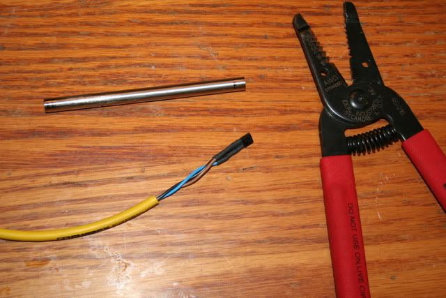
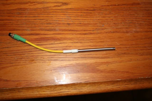
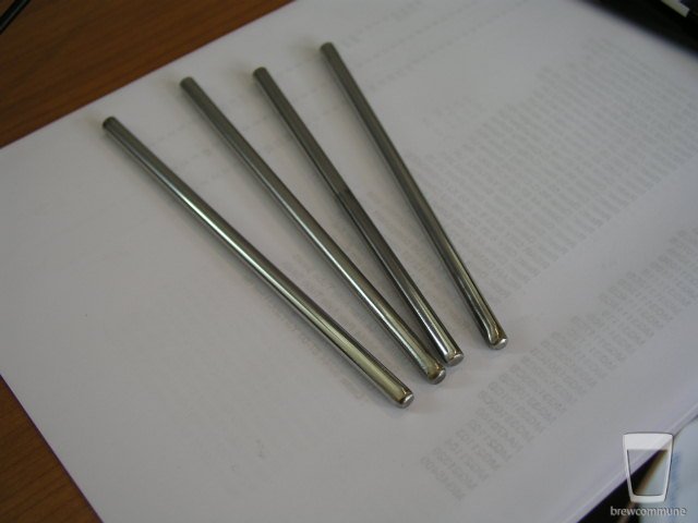
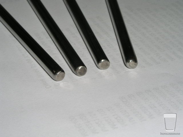
OK, the materials I am using is a length of 1/4" OD Stainless Steel tubing, a sensor cable with M8 (pico) 3-pin connectors, and a National Instruments LM34CAZ temperature IC. It is a molded TO-94 transistor case sensor that fits quite nicely in the tubing, almost a perfect fit as a matter of fact.
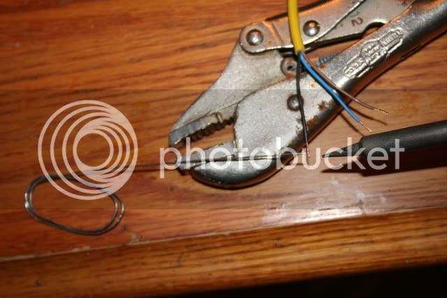
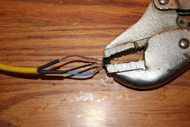
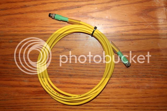
I purchased the sensors from Newark Electronics for around $5 each. The cables can be found from any automation/electronics supplier. The ones I am using are from Phoenix Contact, but any sensor cable will do. You can actually use any small multi-conductor cable as long as it will fit into the SS tubing. I wanted the connectors so I could remove or swap out sensors without having to remove any cabling. I also am a huge fan of shrink tubing. Black electrical tape is fine if you are insulating split bolts on a motor connection or repairing a handlebar grip. But you can't beat shrink tubing when it comes to insulating small electrical connections as well as providing strain relief for the cable.
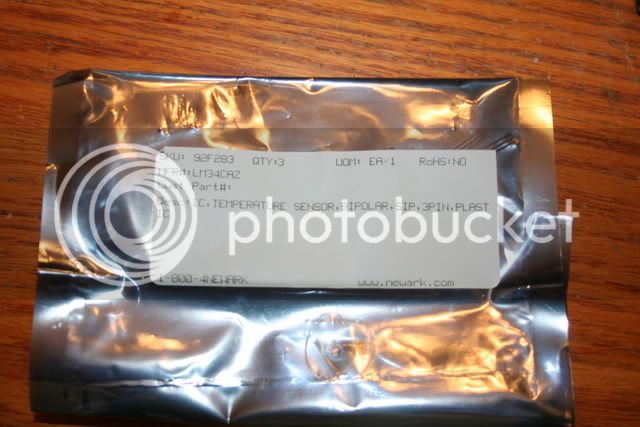
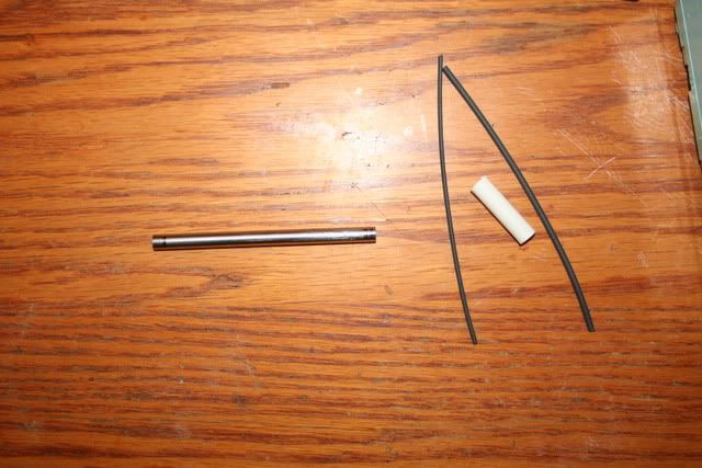
img_1076.jpg


img_1077.jpg


img_1078.jpg
 
I started by cutting the "MALE" end of the cable to the length that I wanted, which was about 6 inches. I stripped the jacket back about 1-1/2", being careful not to nick the conductors. I then stripped the conductors about 1/4" and tinned them with the soldering iron.
At this point, I cut 3 pieces of shrink tubing about 5/8" long and slipped over each conductor. Then, using a pair of vice-grips as a combination vice and work-piece holder, I clamped the temp sensor GENTLY. Remember, it is made of a bakelight material which is brittle. It won't take a huge about of abuse without fracturing.
One at a time, I laid each conductor along side its respective pin and applied just enough heat with the soldering iron to flow the solder that was already on the wire. No need to add more solder since we aren't making a structural connection. Once the soldering was complete, I slid the shrink tubing into position and whipped out the heat gun.


img_1079.jpg


img_1081.jpg


img_1082.jpg
 
Now you simply push the sensor into the piece of tubing until it is about 1/8" from the end. I used a thick piece of shrink tubing that is adhesive-lined to not only hold the cable in place, but also provide a strain relief. *** EDIT - I am no longer recommending the use of 5-min epoxy! I have found that it softens when left in contact with water and sanitizer. This make it totally unsuitable for our use. So, after chatting with Derrin, I ordered 4 of the Stainless Steel probe bodies that he is making. His site can be found here - http://www.stirplates.com/probeends.htm
He shipped them immediately and I had them within the week. They are great and definitely the way to go if you want to make your own sensors. Plus, he is "one of our own" here, so nice to support other HBT members when you can.


img_1084.jpg
 
Does the SS tube or epoxy effect the accuracy of temp probe?

Seems to have no appreciable effect at all. I can lay a probe on a solid surface like a table, let it sit and stabilize for a few minutes. Just by tapping the probe once with my fingertip, the temp will climb a few tenths. Very responsive.
 
Can we get detail how it attaches to your rig? where does the threaded portion come from to screw into the T?

This is the adapter I am using from McMaster-Carr.
P/N - 5182K113 TYPE 316 SS YOR-LOK TUBE FITTING, ADAPTER FOR 1/4" TUBE OD X 1/2" NPT MALE PIPE
It has a double SS ferrule that I am not using. The adapter needs to be drilled all the way through so the probe can extend into the flow of liquid. I found an o-ring that is perfect size and used it in place of the ferrule. I snugged to nut down finger-tight and fired up the pump... no leaks at all.
 
I am not too sure what the Rancos use. I suspect it is just a thermister because the directions say the cable can be lengthened without ill-effect.
These sensors are calibrated at the layer-level and provide 10mV/°F out and are very accurate. I am using them through a USB DAQ that gives me IO capability for my laptop. The program I wrote using LabView...
 
Great Howto! How are you attaching the probe to your plumbing? In the picture it looks like you have a stainless steel compression fitting? Do you have any links, or more info?

One complaint that I've gotten on the BCS-460 probes is the brass compression fitting, some people need (want) stainless. They are also 1/4" diameter, so your solution might work for them as well.
 
Hi, this is a great idea but i'd like to point out something. Isn't the epoxy toxic? I just took a look on my tube of epoxy and it said a ton of warnings. I would be aware of using anything that is not rated as food safe especially at elevated temperatures. Other than that I like the idea of making it your way.
 
Great Howto! How are you attaching the probe to your plumbing? In the picture it looks like you have a stainless steel compression fitting? Do you have any links, or more info?

One complaint that I've gotten on the BCS-460 probes is the brass compression fitting, some people need (want) stainless. They are also 1/4" diameter, so your solution might work for them as well.

Look back right here - https://www.homebrewtalk.com/1106853-post9.html
These are the one I am using....
 
Hi, this is a great idea but i'd like to point out something. Isn't the epoxy toxic? I just took a look on my tube of epoxy and it said a ton of warnings. I would be aware of using anything that is not rated as food safe especially at elevated temperatures. Other than that I like the idea of making it your way.

Well, I haven't experienced any problems to date.... and the third nipple is really not that bothersome.
I will look at that closer when I get home.
 
try this:

McMaster-Carr

McMaster-Carr part # 66525A21

Designed for use with food-processing and packaging equipment and biomedical instruments. This two-part adhesive resists water, weather, petroleum solvents, lubricants, mild acids and alkalies, and other organic and inorganic compounds. Bonds aluminum, stainless steel, steel, polycarbonate, vinyl, ceramic, fiberglass (FRP), and glass. Begins to harden in 2 hours; reaches full strength in 18 hours. Temp. range is -103° to +293° F. Mix ratio is 2:1. Color is amber. Developed in accordance with Title 21 U.S. Code of Fed. Reg., FDA Chapter 1, Sub B Sec. 175.105 and 175.300. This product is VOC compliant in all 50 states as of October 1, 2008.
Size refers to combined amount of resin and hardener.
 
bull8042; on your first posting about the probes you have built with the stainless steel adapter as well the connector at the end of the probe leads, this was exactly what I was looking for from the very start when I got on the waiting list to order a BCS-460 unit from Adam. Your way the probes can be disconnected and the keggles removed leaving the wires secured in a orderly fashion to the single tier stand to the mounted BCS-460 controller. Is this thermistor a 10K ohm unit that's compatible with the BCS-460 that Adam has available?
If i'm understanding correctly those connectors are called, M8(pico) 3-pin connectors? As far as the worry using epoxy to seal the end of the probes just machine a SS plug 1/4" long and press it into the end of the tube, Tig weld it without filler rod for a 100% water tight end plug. The other end with the stainless adapter is perfect that is also what I was looking for all this time vs a 1/4" SS NPT coupling and the brass adapter. It's been a little busy at my end with 8 more spinal injections. Questions I have as I went thru this thread rather fast, on the connectors themselves, are they brass, nickel or gold plated to maintain a stable contact resistance? I have not read thru everything fully and taken any notes on part numbers plus where to purchase them being too sore at the moment. I have four 7' sections of 0.250" OD stainless tubing. Thanks for the pictures and the materials list, i'll have to reread when I have more time. Adam i'll be in touch with you within the next 10 days for that 460 unit. Lab tests and being driven around has me maxed out at the moment. Thanks for sharing your findings bull.
......Carl......
 
That's very well done! One suggestion; after researching LM34s and DS18B20s for a while now, it seems that fastest thermal path to the chip die is through the leads. The plastic case is an insulator, albeit not much of one. I would suggest leaving the heat-shrink off of the ground wire and pin so it can contact the case. I plan on the same thing you did and I really like the connectors. I plan on leaving the ground wire about 3" longer than the signal/power wire and making a couple loose loops so that it can spring to the inside of the tubing and (hopefully) provide a little faster and consistent thermal path to the chip die.
 
That's very well done! One suggestion; after researching LM34s and DS18B20s for a while now, it seems that fastest thermal path to the chip die is through the leads. The plastic case is an insulator, albeit not much of one. I would suggest leaving the heat-shrink off of the ground wire and pin so it can contact the case. I plan on the same thing you did and I really like the connectors. I plan on leaving the ground wire about 3" longer than the signal/power wire and making a couple loose loops so that it can spring to the inside of the tubing and (hopefully) provide a little faster and consistent thermal path to the chip die.

I was thinking about adding 5-6cc of transistor conductive heat paste to the bottom of the probe housing before inserting the thermistor. Once it makes contact press it into the paste until it sinks in and bottoms out. This should more than enough transfer heat heck bull had fast temp responses with the chip installed dry.
Even the thermal paste may be overkill.
 
FYI: This is the cheapest source I have found for M8 Pico cables.

HTM Sensors Store: C-FS3TZ-V075

Cheers

This is great information coming in.
One question; that M8 Pico cable above is listed as straight female, where is the M8 Pico straight male connector? A'm I missing something or file thru this above posted Sensor Store?
 
I was thinking about adding 5-6cc of transistor heat transfer paste to the inside bottom of the probe housing before inserting the thermistor. Once it makes contact press it into the grease until it sinks in and bottoms out.


That couldn't hurt. The idea is to leave a lead as uninsulated as possible to speed heat to the chip die. These are not simple thermistors but actual semiconductors.

Not to hijack, but what is your process for TIGing such thin material? Do you need to use something like an .040 tungsten? The smallest tungsten I have is 1/16" and I was practicing trying to weld some fittings and I just kept burning right through.
 
#1 - Tigging the end is a good idea, just make sure you DON'T have the sensor in place when you do it. The electrical field and heat will destroy the sensor.
#2 - The sensor cable connectors are not gold plated, but will withstand anything you want to throw at it without losing their connection. They are in use on millions of Automation and Robotic cells around the world and are the industry standard.
#3 - Derrin, you may in fact be correct about the body acting as an insulator. BUT, I have tested these and can tell you with 100% confidence that the response time is amazing. You can literally just tap the end with a finger and you will see a temp rise almost instantly. One thing we have to remember, we are not installing a diagnostics system on the space shuttle. It is easy to get caught up in the quest for perfection, and cause ourselves problems in the long run.
You have to remember too, these are not analog devices, but very low voltage ones. If you allow the ground wire to contact the tube, which is in contact with the rest of your rig, it could become an antenna. That would introduce a ton of noise on your signal line that you don't want.
Would it become a real-world problem, well that remains to be seen as I have not had any noise problems at all. However, why take the chance for a percieved gain that you will never realize? As I said, the response is almost instantaneous already. So much so that I have started taking a 100mS average of the signal just to keep my indicators from dancing around so much.
Oh, and Carl, please check with Adam for his opinion as to whether this will work with his system. I don't want to claim suitability for a system that I have no experience with. Not very fair to the man pioneering a brew control system.
 
This is great information coming in.
One question; that M8 Pico cable above is listed as straight female, where is the M8 Pico straight male connector? A'm I missing something or file thru this above posted Sensor Store?

I believe this is the cable you want. It is double-ended indicating that it has a male on one end and a female on the other.
HTM Sensors Store: C-MS3TZ-V075+C-FS3TZ-V075
When cut, it will give you the connector pair that you need without having to buy two cable sets.
The other part number quoted is single-ended, meaning it has flying leads on one end and a connector on the other.
 
#3 - Derrin, you may in fact be correct about the body acting as an insulator. BUT, I have tested these and can tell you with 100% confidence that the response time is amazing. You can literally just tap the end with a finger and you will see a temp rise almost instantly. One thing we have to remember, we are not installing a diagnostics system on the space shuttle. It is easy to get caught up in the quest for perfection, and cause ourselves problems in the long run.
You have to remember too, these are not analog devices, but very low voltage ones. If you allow the ground wire to contact the tube, which is in contact with the rest of your rig, it could become an antenna. That would introduce a ton of noise on your signal line that you don't want.
Would it become a real-world problem, well that remains to be seen as I have not had any noise problems at all. However, why take the chance for a percieved gain that you will never realize? As I said, the response is almost instantaneous already. So much so that I have started taking a 100mS average of the signal just to keep my indicators from dancing around so much.

Yeah, that's true. I did pick up a lot of noise when i was using the LM34, maybe that was my problem. I ended up using the RC circuit per the spec sheet and that solved the issue. They did read instantly though.

Now I'm using DS18B20s but I don't have them built into sensors yet, they are still on a breadboard but I will be ordering some of those cables.

THanks!

I guess KISS is the better way to go.

The DS18B20 is a nice little sensor, but it is calibrated in Celsius. That is the reason I went with the LM34CAZ, it is calibrated in Fahrenheit.
No conversion to deal with in the programming. Easy enough to do the conversion, but one less step for me to deal with.
Also the ±0.5°C Accuracy translates into 1.8*F, whereas the LM34s accuracy is 1*F. Not being critical of your choice in sensors, but merely stating for others following this thread as to why I chose the sensor I did.
 
This sensor is linear? So what technology is it using? Doesn't sound like it is a thermistor or RTD.

Also, you already mentioned that there isn't any significant delay due to the s.s. tubing. However is there any sort of offset in temperature? Have you tried placing it in a cold bowl of ice and water and then take a measurement and compare it with a thermometer?

Looks awesome!
 
Oh, no question the LM34 is a great sensor. My platform is an Arduino and I'm measuring 6 temperatures so I needed to give up all 6 analog pins or use a multiplexer. I chose the DS18B20 because I can run all 6 on a single pin. They do take a lot more code overhead though. I was reading all 6 LM34s with 2 lines of code.

BTW you can get them at All Electronics for only $2.50 each. http://www.allelectronics.com/make-a-store/item/LM34DZ/FAHRENHEIT-TEMPERATURE-SENSOR/-/1.html

Jared311: The LM34 has a linear output of 10mV / *F. The DS18B20 is a digital device, each with their own unique ROM code serial number that when asked to (by address) sends a stream of 8 bytes that have to be converted to usable data in code.
 
I decided to take the digital approach with the DS1624 digital thermometer IC's. Then I designed copper thermowells out of copper piping that screw into 1/2" couplings in my kegs. I haven't tested it yet to see how accurate it is.

thermos.jpg
 
That couldn't hurt. The idea is to leave a lead as uninsulated as possible to speed heat to the chip die. These are not simple thermistors but actual semiconductors.

Not to hijack, but what is your process for TIGing such thin material? Do you need to use something like an .040 tungsten? The smallest tungsten I have is 1/16" and I was practicing trying to weld some fittings and I just kept burning right through.

Derrin; that is not that thin of material to Tig weld, yes I have been in a hurry and kept 1/16" tungsten in the torch welding thinner materials like a 73 BSA gas tank when smaller tungsten was the proper size. This had sharp corners and seams like a Honda 350 "Yuck Box" looking tank not like the early tear drops not prone to vibration crack tanks. Yes I have .040" and .020" tungsten. It depends on the machine besides how long you've been Tig welding. Like a road grader operator some can master the machine some never even after 15 years of screwing up making humps in roadways. In my case over 27 years with Tig, worked with a Tig welder that welded aluminum on aircraft for the Navy's O&R department in Alameda NAS. A aluminum Tig artist bar none in the N.A.S.A. or RAD Lab class. I could never catch him even when he was welding at 80 years old. At 86 he's still a kid and can Tig. Hell his shop at home has 3 phase for the welders alone as a commercial building is next door. The machine I have has a range of 3-385 amps with pulser, background amps on and on. A 1991 Miller Synchrowave 350 fully loaded. I went thru the challenge years ago and and welded two beer cans together with this machine. The 316 SS tubing I have with 0.250" OD has a .035" wall thickness, rather easy to Tig if you have been practicing welding light gauge materals a lot and not rusty. This I mean by not welding for 8 months and right away start on some special low gauge thickness item without "warming up a bit", it comes back in time again but not on something that is a one shot project you blow it your screwed.

bull8042; you know me better than that to weld in the probe end slugs before inserting the temp probes. As far as Adam and his controller project which I also highly respect him as well you bull, I asked Adam about connectors so I can cut and add them to his probes near the keggles for easy keggle removal, cleaning, storage or transporting over 5 or 6 weeks ago on another thread on this forum. This was when Adam had his test crew running the control units with welcomed input from any and all forum members be it good or bad subjective ideas. Also in reply number 12 this thread Adam likes the idea of the stainless adapter with 1/2" NPT vs the brass 1/4" NPT from the customer feedback he has already received and knows about this 1/4" vs 1/2" NTP brass adapter he has. I know with Fluke meters and other probes the connector material must be the same material as the probe wires themselves or a dissimilar metal voltage will be created causing false readings and other problems. I was looking at Omega's connectors but these posted above look a lot smaller, cleaner and better in design. I'm just following you here on this probe project like other members as I already have the 1/2" couplings that I stepped down the OD for a shoulder to the thickness of the keg body for a tight fit flush fit inside the keggles. The couplings are shortened up a little plus the threads on the inner 2/3 of the couplings are bored out and smooth. Only enough threads for the probes and valves exposed preventing crap buildup in the thread roots around the probes. Fully threaded couplings shoulder stepped for screwing on the drains inside the MLT and Boil keggles only plus these threaded adapters keep the coupling threads clean inside.

Questions bull8042; what is the OD of those temp probes in thousandth of an inch and the resistance of them? Are they compatible with the BCS-460 that requires 10K ohm probes? Thanks boss. P.S., calling you boss is not meant as an insult as one member turned it into. You know what I mean from working the trade as a wireman years ago. Thanks for posting this project it's all great information.
Carl.............
 
Are they compatible with the BCS-460 that requires 10K ohm probes?

Trying not to hijack here, but to answer your question, the DS1624 and LM34 based probes are not compatible with the BCS.

But, if you want to save a little coin, you CAN make your own BCS compatible thermistor based probes in a similar manner, just use something like this or this instead of the LM34, and follow the same steps.

The dissimilar metal problem affects thermocouples, but not thermistor (or semiconductor) based probes.

Cheers!
 
Cool project. I'm not an electronics person, but I could follow the excellent instruction you have provided. And make a few of these for my own use. Someone earlier asked if these would work with a Love controller. Was this answered and I missed it? If not is there a controller that will read the input from these that I can buy and use in my brewing system? I'm also not a programmer. But if there is a program ready to load and use I could do that.
 
There you go again Adam, on top of your game to the point with quick replies, that fellow brewers is the reason why Adam will be a successful business person besides the high quality products he has available. I have been given the song and dance taking 3-5 emails for one simple question to be answered by other manufactures. Adam; I already have my 1/2" coupling machined and ready to go plus this allows for changing the coupling to do other functions this is why the intrest in the SS 1/2" male NPT adapters to the probe end with seal and gland nut. This has been the only progress made as i'm down this week in the house only recovering. I feel like I lost in the bat beating from yesterdays injections. I'll be funtional, can walk with cane by next week will order the 460 before the spiders call it their home. Thanks Adam. There is a hell on earth i'm going thru it at the moment. Carl.....
 
Trying not to hijack here, but to answer your question, the DS1624 and LM34 based probes are not compatible with the BCS.

But, if you want to save a little coin, you CAN make your own BCS compatible thermistor based probes in a similar manner, just use something like this or this instead of the LM34, and follow the same steps.

The dissimilar metal problem affects thermocouples, but not thermistor (or semiconductor) based probes.

Cheers!

Thanks. I was about to answer these questions, but I see you beat me to it. Interjecting requested information is not hijacking at all. :mug:

Cool project. I'm not an electronics person, but I could follow the excellent instruction you have provided. And make a few of these for my own use. Someone earlier asked if these would work with a Love controller. Was this answered and I missed it? If not is there a controller that will read the input from these that I can buy and use in my brewing system? I'm also not a programmer. But if there is a program ready to load and use I could do that.

Thanks for the kind words. I was hoping this would be helpful to someone, especially since I have garnered so much information here myself.
I apologize, but I have not researched to Love or Ranco controllers, so I really can't answer your question. Maybe one of the others on here could jump in and help out if they have one.
 
The B57164 Series with a resistance tolerance of 5% is out of the question for use as it is 5.5mm wide no way will it fit inside a 1/4" OD SS probe ID tubing. The price is great at $0.58 each.

The B57560 with a resistance tolerance of 1% plus only 2.3 mm +0.2 mm, this will fit inside 1/4" OD SS probe tubing. The price is $3.70 each. Add $14 for the M8 Pico cable male /female ends that's 5 meters long plus the SS 1/2" NPT adapter, shrink tubing and labor your way over the $16 price Adam is asking for his probes. One must think about this for the gain of having a 1/2" SS adapter at $13.53 each plus the connector for each probe times how many probes you will need. Your at $31.23 each complete probe before adding shrink tube, shipping and taxes if applied.

What you stated is correct. However, I would have to have the adapters regardless of what I use, homemade or purchased. So I don't count the cost of the adapter as a downside.
The other side of the coin, since I have been designing and building automation for the last 15+ years, I have a bunch of "stuff" laying around anyway. Regardless, the purpose of my post was not to try to necessarily save a ton of money, but rather make use of what you have access to. We are DIY'ers, so this is another way to take it one step further.
Also, you are only comparing this to what Adam is selling. An identical probe in comparison to the one posted here and purchased from LabJack is $49 without any QDs or adapters, so in that case, it IS saving a ton of money.....
 
bull8042; i'm not looking at it as a money saving probe project it's getting me what I want. A 1/2" SS fitting plus a disconnecting means to remove the keggles. Plus this would allow me to make a custom built probe around 18" long inserted thru the lid of a 20 gallon fermenter for readings in the center of the fermenter. Now this brings up another idea.
What would it take to build a seperate unit with a digital readout in degrees F that I can connect to the probe in the frementer in the refrigerator but mounted on the outside?
That way the BSC-460 unit can stay with the brew stand ready to be programed or for brewing while not attached at all to the fermenter some distance away or at another location? Reason mentioned I have two properties and would rather have the refrigerator with fermenter at one location due to space reasons and keeping the brewing system with the BCS-460 at my house. I'm at the other property daily besides I have more space there for another refrigerator than at home.
I may of answered this myself thinking if I could make a resistance to degrees F conversion chart and use one of the Fluke 87 or 77 meters to read the resistance of the thermistor in the fermenter.
Is this possible or do I need a power supply with voltage applied to the thermistor to get a meter reading or direct readings on a unit in degrees F?


Therimistor output is not linear, so without a pretty large lookup chart, you wouldn't be able to just measure the resistance.
temp_plot~0.jpg


This is a graph I did with a 10K thermistor glued to a DS18B20. It's a temp vs the analog value on a microcontroller pin, but it still give you an idea of what the thermistor algorithm graphs out like.

You could just build another probe and use an LM34 like the OP. You would have to supply it 5 clean volts but it provides 10mV per *F output and a voltmeter would quickly tell you what temperature it was. ie: 850mV would be 85*F.
 
Inspired by Bull's beautiful work on these I decided to make my next probes from SS but not wanting epoxy or silicone for fear of it eventually leaking I decided to TIG weld the end shut. I just recently got this welder and my finest welds are embarrassing at best but I figured I'd give it a shot anyway. I got some 1/4" OD X .028 wall SS tubing and 3/16" SS rod that fit the ID fairly tight.

Welding .028 wall material to 3/16" rod proved to be quite a challenge, for me at least. After burning an inch or so of tubing away, I finally figured out that the best way to do it was form the puddle on the rod and then use the torch to quickly push it to the tubing until they fuse. Anyway, here's the result:


SS_Probes.jpg

SS_Probes_2.jpg
 

Latest posts

Back
Top