Magic Chef Beverage Cooler - MCBC58DST

Homebrew Talk - Beer, Wine, Mead, & Cider Brewing Discussion Forum

Help Support Homebrew Talk - Beer, Wine, Mead, & Cider Brewing Discussion Forum:

This site may earn a commission from merchant affiliate links, including eBay, Amazon, and others.

FunkedOut

FunkedOver
Joined
Mar 23, 2017
Messages
849
Reaction score
417
1st post!

Let me start by thanking you all for the smarts you share.
I know nothing about making beer, but sampling home-brews is planting the bug in me. I may just end up taking the plunge.

So I am starting this journey backwards. I want to have beer on tap at the home front. I have the good fortune of a home brewer making a couple batches of beer for me. I decided now is the time to get the draft flowing rather than buy bottles.

I was searching around for a mini-fridge that would hold a couple of corny kegs, or a couple of sixth kegs, and a bottle of CO2. I may add a tower in the future, but picnic taps for now will do.

In that search I ran across this site. I also decided to check out what the Home Depot had in store so I could take a tape measure to the inside and got lucky with the Magic Chef Beverage Cooler (model number: MCBC58DST).
They had one left in the box and it was on clearance for $236. Not exactly a craigslist steal but not terribly expensive either. Here's a short list of features that made it stand out for me:


  • Big enough interior to fit 2 corny kegs (or 2 sixth kegs) and a 5lb CO2 bottle with no modifications
  • No freezer section / cooling plate on the rear wall
  • Internal fan that runs while it cools
  • Digital thermostat (35*F - 54*F)
  • Blue LEDs on the thermostat and interior lighting
  • Removable glass shelves
  • Stainless door with huge tinted glass window
  • Black sides and top
  • No cooling space required behind or on sides
It is designed for stand alone installation or built-in to a counter, so the heat vents out of the front, under the door. This allows me to push it back against the wall in the dining room, putting it right where it needs to be.

I brought it home and took the first step before committing to owning it; checking the cooling capability...

closed.jpg


open.jpg
 
Unboxed it, plugged it in and set it to 35*F.
Put a pair of Taylor 5924 thermometers in there and let it sit overnight.

Next day, observed it would run between
37*F and 40*F while the Taylor's measured between
42*F and 45*F.

That's not cold enough for me. I needed this to get colder so I searched online and found this thread that contains a couple links to other threads:
https://www.homebrewtalk.com/showthread.php?t=76948

One of those threads discuses how to calibrate the digital thermostat, but my circuit board did not have those pins. The only other options were to trick the thermostat with resistors, or bypass it and use an external controller.
I chose to avoid the external controller to save the cost and keep several of the features of the original system: auto defrost, internal fan on cool and those sweet blue LEDs...

taylor.jpg
 
To fool the thermostat into thinking the temp sensor is sensing a temperature warmer than it really is, you need to lower the resistance the sensor provides the thermostat.
The easiest way to do this is to wire in a resistor in parallel with the temp sensor.
But what value resistor to use?
After looking up a few typical values of these sensors, I decided a 50kOhm pot would put me in the ballpark so I could turn a knob to dial it in.
Ended up being 33kOhm was perfect.
I decided to wire in a resistor, rather than the pot, so it would be constant and I could use the digital settings as a final trim.

With the 33kOhm resistor in parallel, I managed to get the internal temps down to 25*F!
With the unit set to 37*F, internal temps would fluctuate between 25*F and 28*F.
Setting the unit 54*F brings up the high to right around 48*F.

What if I wanted to use this as a fermentation chamber?

Looking at those typical values again, a 5kOhm pot would be just right to find my second resistor value.
2.7kOhm resistor in series covers a range of 50*F to 76*F.

So I made this little harness that plugs inline between the display box / controller and the wiring from the unit itself. There are two pairs of wires on this connector, a pair (black) of the temperature sensor and a pair (white) for a second sensor to kick on the auto-defrost cycle.
I attached a circuit drawing incase it would help anybody out.

A DPDT switch allows the selection of two modes:
25*F - 48*F
&
50*F - 76*F

board.jpg


harness.jpg


circuit.jpg


installed.jpg
 
Glad you found this helpful. I went looking for this thread when I bought it and figure it might help someone out!

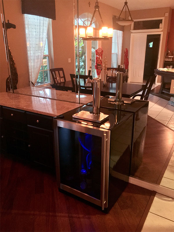
Finally decided to take the dive and make this a kegerator.
I'll post some more details for those in search of them...

I tried to remove the black metal skin to reinforce the tower to come but after removing all the screws, I found that the skin is really well glued down and removal would be destructive and proceed without removal.

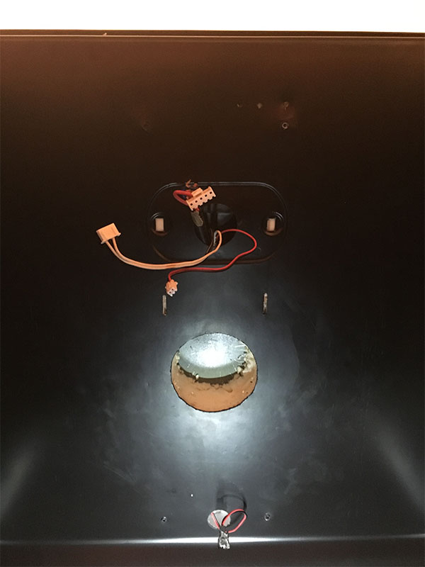
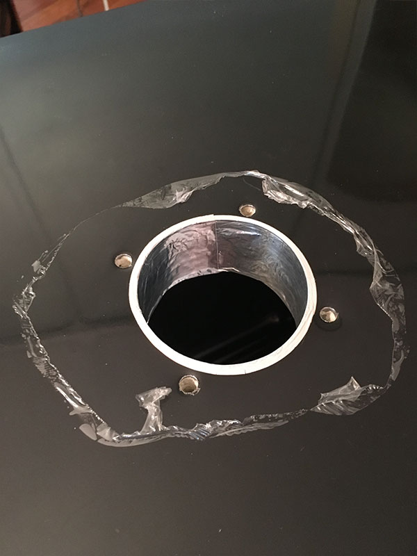
First pic, you are looking at the ceiling of the fridge.
You can see the front most edge of the ceiling at the top of the pic.
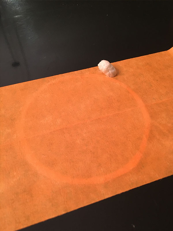
First strip of tape at the top is where the controller starts (when installed).
The controller ends at the second strip of tape.
Then there is the 3" diameter circle that is centered (side to side) in the fridge.
And finally a strip of tape marking where the regulator gauges clear when the 5lb bottle is sitting on the hump at the rear of the fridge.
The tape strips are 1" wide.

Not much choice on where to make that tower hole.
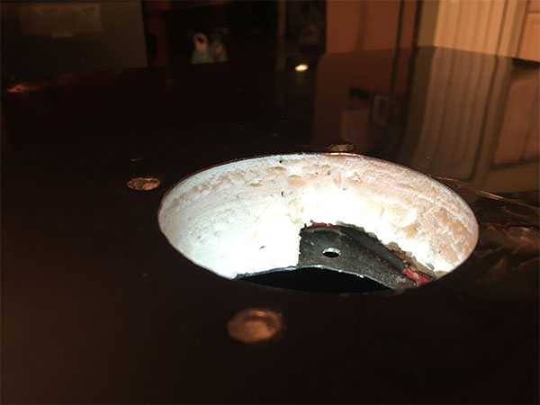
Carefully cut through the plastic liner with an exacto knife, and carefully picked away at the insulation with a small flat screwdriver.
Not a wire in sight.
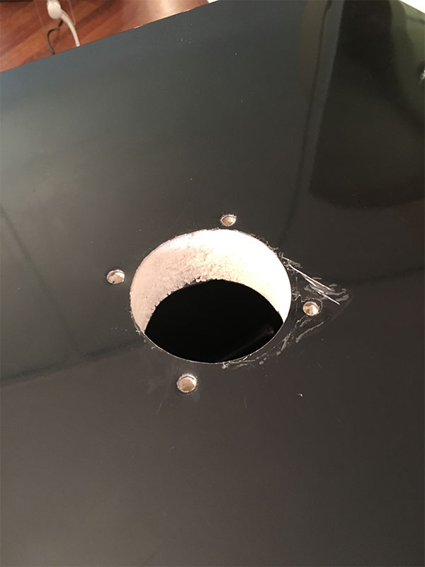
Drilled through the metal skin with a 3" hole saw and deburred the hole.

Used the tower itself to mark the four screw holes and on the last hole, drilled right through both the black and red wires that power the fan at the back of the fridge. Don't do that.
Picked away at the insulation and pulled a bit on the wires to where I had enough room to repair the wires with solder and heat shrink.
Taped up the holes and filled with great stuff.
Let dry overnight...

1.jpg


2.jpg


3.jpg


4.jpg


5.jpg
 
With the repair out of the way, I can continue making progress.
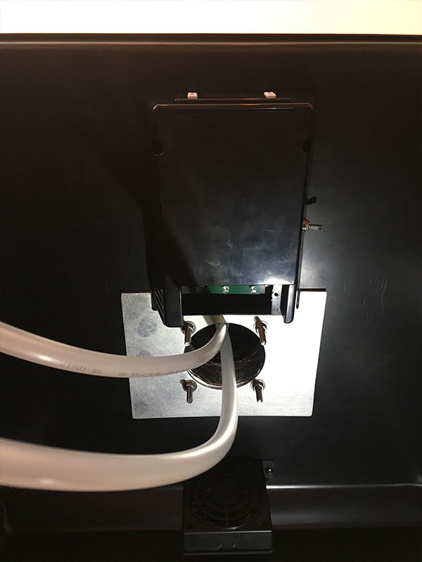
I lined the hole with aluminum tape to keep the foam from flaking off.
Then made this plate for the inside of the fridge to keep the tower from wobbling when working the faucets.
Last pic is a view from inside after all is said and done.

The tower is stiff enough to tilt and lift the fridge off its feet without flexing.
Can't ask for more than that.

The rest from here on out is the same old kegerator stuff that's been covered before.

1.jpg


2.jpg


3.jpg


4.jpg
 
Great thread!
I have the Vissani version of this same fridge and am looking to do what you have done with the 2.7kOhm resistor to bring the temps up to fermentation chamber temps, as that is my main use for the fridge. Not really interested in bringing the temp lower, it already hits 38*F on the lowest factory setting of 35*F

Mine looks a tiny bit different, black wires instead of grey. But same model #

Couple questions, I assume for my use I would just run one black wire to one side of the switch without a resistor and it would operate as intended from the factory? Then on the other side of the switch i'd wire the other black wire to it with the 2.7kOhm resistor and it would allow me to trick it into running at higher temperatures?
Does it matter which black wire I put the resistor on? Why are there 2 black wires for the temp sensor in the first place?

Here is the wiring schematic on my fridge.
 

Attachments

  • wiring.JPG
    wiring.JPG
    56.7 KB · Views: 0
Leave one black wire intact.
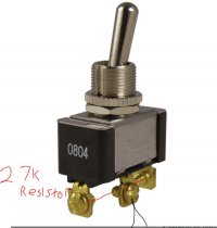
Cut the other black wire, and connect it to a SPDT (single pole double throw) switch.
The switch will have 3 lugs. Connect the two cut ends of the black to the center lug and one side.
Connect your resistor to the two side lugs.

There are two wires because that’s how circuits work. The board needs access to both sides of the sensor to do it’s thing.
 
Ok I think I got it, sorry for having to break out the crayons in order for me to get it!

Cut 1 of the black wires (doesn't matter which), and connect both to the center.
Then wire the resistor across the top and bottom lug.

Off position will operate like factory settings.
On position will pass the current through the resistor allowing for a higher temp range.
 

Attachments

  • wiring2.JPG
    wiring2.JPG
    46.8 KB · Views: 0
Move one of the black wires to one of the other lugs and Bob’s your auntie!
 
I would recommend a potentiometer to get the resistor value right.
Just because 2.7k worked for me, doesn’t mean it will work for you.
 
Back
Top