!HELP! DSPR-120 issue?

Homebrew Talk - Beer, Wine, Mead, & Cider Brewing Discussion Forum

Help Support Homebrew Talk - Beer, Wine, Mead, & Cider Brewing Discussion Forum:

This site may earn a commission from merchant affiliate links, including eBay, Amazon, and others.

schnackshack

Member
Joined
Jan 11, 2017
Messages
19
Reaction score
4
Hello,

Wondering if anyone can offer any insight as to how I should be wiring the boil controller for the setup in this guide:
https://www.skrilnetz.net/how-to-build-a-brewing-control-panel-herms-240v-30-amp/
I'm ended up getting a DSPR-120 to operate boiling (the guide calls for the DSPR1), but I'm getting some odd behavior when trying to set up this as the controller.

The main problem I am having is that when the Boil element is selected, there is no power sent to the element through my contactor **when the element is plugged in**. When I have no cable's plugged into my Boil kettle receptacle, power is sent, LED power indication goes on to that receptacle. It seems like something to do when the element is actually attached…maybe..

I’m also getting on my DSPR-120 an error code 'orAL' and 'PrAL'. This shows up not matter what I do. Typically means a bad sensor, or RTD wiring.

So, I’ve checked that. Some tests I have run:
  • The element runs fine when plugged into the HLT receptacle, so I have confirmed that cable and element are functional.
  • The XLR cables have been swapped around and tested, those are functional.
  • The RTD cables within the box, have been swapped to the SYL-2352 PIDs to test XLR receptacle and RTD cables, again they worked fine.

So It's a behavior that only comes up when I have an element actually attached (via 240V boil receptacle).

Any wiring diagrams you can send would be helpful. Any insights, anything. Help!

Thank you!
 
The element power lamp coming on when when the element is not connected is normal, and does not indicate that power is being applied to the element outlet. It's caused by the normal leakage current of an SSR.

The "orAL" error message means the controller doesn't detect a temperature probe connected. I can't find
"PrAL" in the manual.

The DSPR120 has different terminal assignments than the DSPR1 (and other common PIDs.) Did you adjust the wiring to match that of the DSPR120?

1629861933251.png


Brew on :mug:
 
Thanks for the suggestion on wiring. Yes, I have checked and double checked my wiring and it is done according to the DSPR120 manual.

As for the LED, that comes on and I have tested the receptacle with a multimeter, voltage is present as expected.

Im starting to wonder if I have a faulty DSPR120?
 
Thanks for the suggestion on wiring. Yes, I have checked and double checked my wiring and it is done according to the DSPR120 manual.

As for the LED, that comes on and I have tested the receptacle with a multimeter, voltage is present as expected.

Im starting to wonder if I have a faulty DSPR120?
The voltage on the receptacle with the SSR off is also normal. SSRs are not perfect switches. The voltage you measure when the SSR is off will depend on the resistance that exists between the terminals (quite high when the element is disconnected.) The net is: you can't really test an SSR with just a voltmeter.

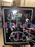
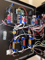
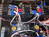
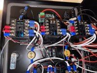
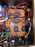
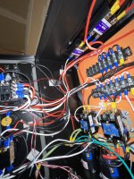
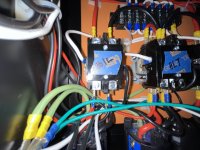
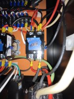
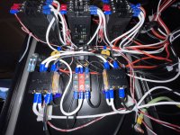
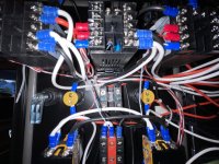
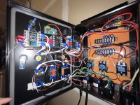
Can you post some pictures of your panel wiring? Good focus, and multiple angles are needed for wire tracing.

PIDs and DSRPs can fail, but it is rare. Best to rule out more common failure modes before blaming the controller.

Brew on :mug:
 
I also forgot to mention the SSR's flow into a contactor, and what I measure in voltage is the same on both the HLT and Boil receptacles, when the respective element is switched on with my three way switch.

Anyway, here's a bunch of images. I should state that the red and black are hot, white is neutral and green is ground, I followed the general color codes.

Thank you for the investigation!!

IMG_0405.JPGIMG_0406.JPGIMG_0407.JPGIMG_0409.JPGIMG_0410.JPGIMG_0411.JPGIMG_0412.JPGIMG_0413.JPGIMG_0414.JPGIMG_0415.JPGIMG_0416.JPGIMG_0417.JPGIMG_0418.JPGIMG_0420.JPGIMG_0421.JPGIMG_0422.JPG
 
Remember, you cannot put a typical volt meter across the outputs of a Solid State Relay and get an accurate indication of On/Off. You need to have a load across the output.

The heating element can be the load. If you do not want to be powering your element on and of during testing, a 100 watt incandescent light bulb makes a good dummy load.
 
I appreciate the insight. And this is why I love this forum, people teaching people and spending time to do so out of their own good heart!

Got a bit of an update yesterday. I was on the line with a tech at Auber Ins. and we tried all sorts of tests, and we’ve both concluded it has to be a bad unit.

Getting a replacement (and upgrade to a DSPR300) so we’ll see what happens when that gets here!
 
It's common for RTD probe manufacturers to just pick any random pinout. I'm assuming Auber advised you to try a bunch of different connections of the three probe wires right? This doesn't damage anything and you can literally just swap the three into the different combinations and see if the display stops flashing ORAL.
 
I actually just received my replacement unit, a DSPR300, installed it, wired it up identical to the DSPR120, hooked it up to a sensor and power and guess what…

— NO ERROR!! — 🤩🥳

Sending the old unit to Auber who’s gonna test it for a conclusive answer, but until then, I think it’s safe to say I had a bum unit.

Brew time! Thanks to all for the thoughts and help on this!

🤘😁🤘🍻
 
Back
Top