Glycol Chiller Build / Single Pump Design

Homebrew Talk - Beer, Wine, Mead, & Cider Brewing Discussion Forum

Help Support Homebrew Talk - Beer, Wine, Mead, & Cider Brewing Discussion Forum:

This site may earn a commission from merchant affiliate links, including eBay, Amazon, and others.

radllc

Member
Joined
Jul 30, 2020
Messages
7
Reaction score
1
I am designing a glycol chiller with a 5,000 BTU A/C unit. I would like to have only one pump with two relay temperature controllers (eg a Baylite controller). The first temperature controller will turn on a pump and the A/C unit only to recirculate the glycol until it reaches my set temperature. The second temperature controller will switch a 24 volt solenoid valve (opening it) but then I also want it to switch the single pump on if needed. If the pump is already running in recirculation mode, I don't need to switch it on, just open the valve. If the pump is not running, I need to switch it on along with opening the valve to send glycol to my fermenter. I will be using a manifold. The manifold will always pass the glycol through it (recirculation) when the pump is running but if the output solenoid valve is closed, the fluid will be blocked from going to my fermenter, and if open will be sent fluid to my fermenter.

I understand how to do this if I were to use two separate pumps /circuits, but with this design, I have two inputs that could both be on (one calling for recirculation and the other calling for fermentation temperature control).

I am trying to figure out if there is some relay that can take two inputs and switch a single load (my pump) if one or both of the inputs are on. Not sure how to do this or I can scrap the idea and go with two pumps with separate circuits, which I understand how to do. Note, I also don't want to keep my pump running all the time.

Any ideas or should I just go to the standard multi-pump design?
I think I figured this out. I can use relays to do this.
 
I don't know what the "switches" look like, but you can connect two mechanical "normally open" switches to one end of a relay coil (and power to the end of the coil). If either, or both, of the switches close, the relay will turn on.

If your switches are driving DC voltage, you could use OR-ing diodes to tie them together into the relay coil, then ground the other end of the coil.

If your switches are driving AC (i.e., 120VAC), you're best off using contactors or relays between the switches and the relay coil you're trying to control.
 
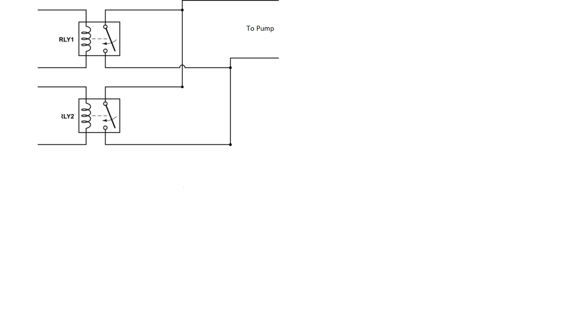
The two inputs are 110v and the single output is also 110v. Couldn't I accomplish this with only two relays on the input side? If either input is switched on or both are switched on, the output or the pump in my case is energized. Edit: The diagram would look like this. Wouldn't this work, and I am assuming that the relays prevent any backloading against the inputs if both are switched on (and remain on) at the same time?


Relay Diagram.jpg
 
Last edited:
Your diagram depicts two switches wired in parallel, which is fine for this application. The pump will get power when one or both of the switches are on. I’m thinking about doing similar. Depending on your needs, you may also want a third switch that triggers on a timer so that there is a recirculating cycle every so often to keep the glycol bath moving and your lines from getting warm or stale when the ac isn’t running. I have a longer run to my fermenters. So I want to keep things moving. Leaving the pump on a 100% duty cycle is another option, less starts and stops for the pump, and easier to hook up this way.
 
I am going for efficiency as much as possible in my design. I have read a ton of schools of thought on this - but won't recirculating the pump only when needed to lower the temp of the coolant be sufficient enough? I am thinking about going with an external self-priming pump vs a submersible. Out of curiosity, if only using a single pump, what would be sufficient for this design. My coolant lines will run up to 8' max and I am thinking of having only two zones (three if you count the recirc loop) - for example I might be fermenting, doing a wort chill, and recirculating at the same time. Thanks for the input.
 
Yeah is all seems like 6 of one and half a dozen of another at a homebrew scale. Starts and stops cause wear and tear on the pump, but so will running it all the time. It’s dead simple to just plug in the pump as always on, but definitely not as cool, or fun. I have longer lines that I want to keep cool to prevent a slug warm of coolant from running through my fermenters. I’m even thinking of doing the parallel switch wiring anyway and using the timer to dial in a duty cycle or schedule. That would let me do things like have the pump recirculating during the warm part of the day, but stay off when it’s cool at night. It’s a few more parts and complexity, but opens up some options.

As for pumps, I have a few submersible fountain pumps ranging 350-500 gph that work just fine. I figure they are relatively inexpensive to replace if they wear out or upgrade if I add another fermenter output, etc… The thing to remember is to fight against gravity as little as possible, and let it help you where it can. External and self priming makes me think of a 12v RV water pump which are pretty noisy in my experience, and tend to be high pressure with limited flow rate. Flow and head are what is needed not necessarily high-pressure.
 
The two inputs are 110v and the single output is also 110v. Couldn't I accomplish this with only two relays on the input side? If either input is switched on or both are switched on, the output or the pump in my case is energized. Edit: The diagram would look like this. Wouldn't this work, and I am assuming that the relays prevent any backloading against the inputs if both are switched on (and remain on) at the same time?


View attachment 783833
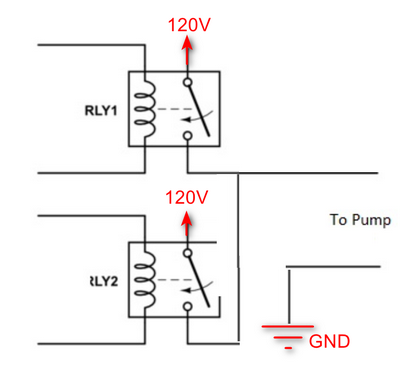
Yes, that would work. However, ... gimme a sec...

... this is what you want

1665863946945.png
 
Last edited:
@radllc-You may already have an answer (my electrical diagramming skills are poor) but I wanted to mention that what you are asking for sounds very close to what is called an end switch on a zone valve controller for radiant heating zones. When a t-stat receives a call for heat, the zone valve is opened, then the signal goes to the end switch which makes, causing the aquastat to turn on the circulator (pump) and the boiler. My pump in my heating system doesn't recirculate, but I'd bet there's a heating system where it might. I'm thinking that if you had a three valve controller with three t-stats, you could put the third t-stat on a zone and let that zone be the recirculation zone which if the t-stat called for cold the end switch would turn the pump on and the AC. A zone valve controller is just a premade set of switches basically with a transformer. The schematics would show you how it is wired. I'm not particularly good at reading the schematics, so I can't explain it any better but I think the end switch is what you are looking for.
 
Yes, that would work. However, ... gimme a sec...

... this is what you want

View attachment 783844
Thanks all for your help / replies! @passedpawn, in your diagram, my understanding is you are switching the hot inputs and my ground and neutral (which is not shown) come into my pump externally / outside of the relay. Being new to relays, is it okay that the two hots could be energized at the same time, which in my case is possible if one temp controller calls for recirc and the other calls for fermentation cooling. This is exactly what I want, but double checking. Thanks again.
 
Thanks all for your help / replies! @passedpawn, in your diagram, my understanding is you are switching the hot inputs and my ground and neutral (which is not shown) come into my pump externally / outside of the relay. Being new to relays, is it okay that the two hots could be energized at the same time, which in my case is possible if one temp controller calls for recirc and the other calls for fermentation cooling. This is exactly what I want, but double checking. Thanks again.
Yes, it's ok. BTW, please replace GND with Neutral in my drawing. Derp.

I don't think I'd do it that way though. I'd probably just use one relay and combine the two outputs from your controller to the single relay's coil. That'd be simpler and accomplish the same thing.

Please be careful and test a bit before you put your gizmo into service. I'm not 100% following what you're doing, just giving suggestions.
 
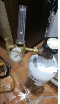
I took a chest freezer and plumbed it with a circulation pump. I have qty (2) counter coolers. One takes water from house and the second takes a glycol mix from the chester freezer. I make 100 gallons at a time. Depending on the size of your brew run, it is helpful to use the house water to first cool the wort out of the fermentor THEN use the chilled water/glycol to take it to pitching temp. after the coolers I run a 1 micron filter , then a 0.5 micron diffusion stone in a "Tee" connected to pure oxygen , then inline static mixer as it travels to the fermentor. I am always using yeast nutrient added the same time as whirlfloc (20 minutes left in boil) . All chilling lines from house water and glycol chiller are quick connects. I use a special filter housing that can handle high temp. When I first start, I top off the brew kettle to the top , get it boiling and run 10 gallons of of boiling water through the complete circuit that would travel to the fermenter. After 10 gallons run through and sent to drain I return the silicone hose ot the brew kettle and let it run for 15 minutes in a loop with boiling water so everything in the fermentor supply line is totally sterile. The fermentor itself is filled with water to the top and star san added and agitated with a drill and stainless paddle mixer. After letting it sit for 30 minutes the fermentor is drained with sterile CO2 flowed into the tank with the hatch cracked to prevent overpressure. This results in the tank and supply circuit are fully sterile.

It is easy to find an old chest freezer and you can get a cheap circulation pump on ebay. If you take the supply from the bottom, never have an issue with priming or run dry. Gylcol is very slippery stuff, so I would wonder about the seals of a submerged pump.
 

Attachments

  • 0ec19d7e-f535-435f-9ea1-467a4c0d41e6.jpg
    0ec19d7e-f535-435f-9ea1-467a4c0d41e6.jpg
    105.2 KB · Views: 0
  • 7e02c2f1-fdde-473b-ba4d-0b65b08974a9.jpg
    7e02c2f1-fdde-473b-ba4d-0b65b08974a9.jpg
    166.2 KB · Views: 0
  • WhatsApp Video 2022-10-14 at 20.50.42.mp4
    1.4 MB
  • O2.JPG
    O2.JPG
    51.8 KB · Views: 0
  • IMAG0006.jpg
    IMAG0006.jpg
    1.1 MB · Views: 0
Last edited:
Back
Top