Float switch wiring help

Homebrew Talk - Beer, Wine, Mead, & Cider Brewing Discussion Forum

Help Support Homebrew Talk - Beer, Wine, Mead, & Cider Brewing Discussion Forum:

This site may earn a commission from merchant affiliate links, including eBay, Amazon, and others.

BlackTieBrewing

Well-Known Member
Joined
Nov 10, 2008
Messages
145
Reaction score
2
Location
Ontario, Canada
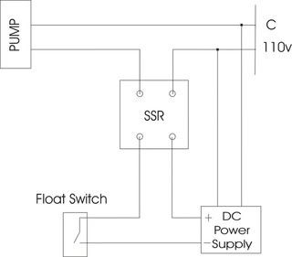
So I'm working on my Brutus build and it's coming along nicely, the control panel is wired and Love controllers are configured. I want to add a float switch so I can have an auto sparge mode. I'm planning to run low voltage DC current through the float and to an SSR. I've already bought the SSR, a stainless float switch and a SPDT center off toggle switch. The only thing I'm not sure about is how to wire everything to my SPDT switch so that in ON mode the pump is on, in OFF it is off, and in AUTO it only comes on when activated by the float switch. If someone could explain how to wire it up or has a good diagram that would be great. This is the only useful one I've found so far but doesn't have all the info I need.

FloatSwitchSchematic.jpg


Found it here: http://www.thebrewingnetwork.com/forum/viewtopic.php?f=3&t=9649

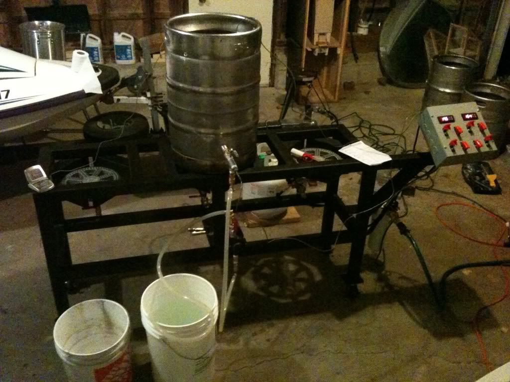
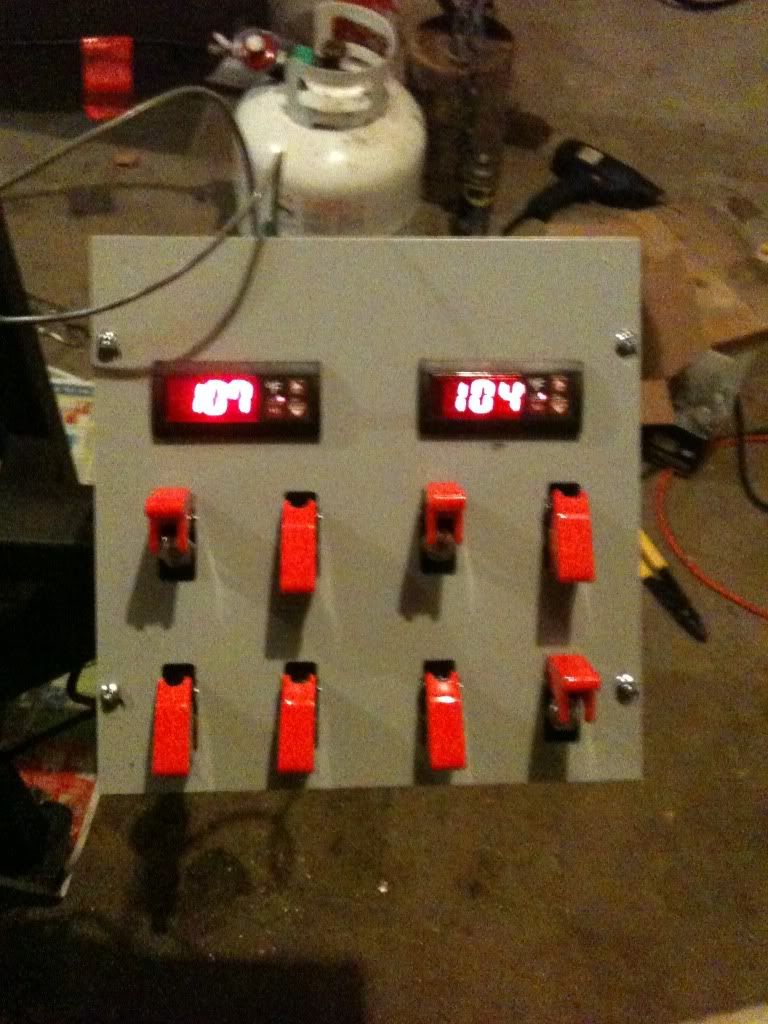
And here's some pics of my Brutus coming along, still a work in progress but should be operational in 2-3 weeks once I get the rest of my parts.

brutusbuild010-1.jpg


brutusbuild011-1.jpg
 
does you float switch have 3 terminals ?


it should have a Load, a NC and a NO lead/terminal on it
also does you SSR have a low volt DC trigger?
Low volt like 12vdc. I have seen them with low volt AC triggers( 24vac)
 
do you have them now?

The SSR looks great

the float switch is kinda odd, the site is not very descriptive

but you should be able to use those items.

The AC side you will beed to put the SSR on the Load or Black wire( if standard wiring is used) connect the neutral directly.

on the DC side( my opinion) I would directly wire the positive side to the SSR and use your float switch on the negative side (again this is only My opinion) after you figure out what you want that switch to do

Sorry I am not a MS paint artist ! or I would draw a picture
 
On your SPDT toggle switch, the center lead will be the negative input from your DC converter

one of the outside poles will go directly to the SSR and the other will go to the float switch !!


I didn't register the switch untill just now
sorry

-Jason
 
No i don't have them yet, I have the SPDT switch, the SSR should get here sometime this week and the float switch I just ordered so it probably won't be here for a while. I am planning on having the wiring done like it is in that diagram like you said with the float on the negative side and positive in to the SSR, I'm just trying to figure out how to wire everything in to my SPDT toggle switch so I can have it run at a constant on in one mode and automatically in the other while being off in the center position.
 
On your SPDT toggle switch, the center lead will be the negative input from your DC converter

one of the outside poles will go directly to the SSR and the other will go to the float switch !!


I didn't register the switch untill just now
sorry

-Jason

Thanks, I was typing out my reply so I didn't get that till I already posted mine.
 

Latest posts

Back
Top