Electrical advice and wiring help for fairly simple RIMS system

Homebrew Talk - Beer, Wine, Mead, & Cider Brewing Discussion Forum

Help Support Homebrew Talk - Beer, Wine, Mead, & Cider Brewing Discussion Forum:

This site may earn a commission from merchant affiliate links, including eBay, Amazon, and others.

JJzeJetplane

Active Member
Joined
Aug 23, 2012
Messages
32
Reaction score
1
Location
Charleston
Ok, so I'm ready to start upgrading my piecemeal all grain system to something a bit more automated. I like the idea of a RIMS system so that I can better control the entire process so that duplicating that amazing brew I come up with one day will be a cinch. I also am excited to be able to start incorporating step mashes in my brewing repertoire. Here is how the equipment will be set up.

The mash tun is equipped with a 1/2" NPT ball valve. A hose then connects this to my March 815 pump. From the pump, there is a tee and a ball valve on each output of that tee, one for the recirculating and another to go to the boil kettle. The recirculating output will then run past a thermocouple to precisely control the temperature. This will control the inline water heater that directly follows. From the water heater, it will then enter another tee, one end of which will have another ball valve and be hooked up to my hot liquor tank. The other end will reenter the mash tun and flow through the sparge arm.

Once I am ready to sparge, I will open the ball valve between the pump and the boil kettle and close the one to the inline heater. Then I will open the ball valve between the hot liquor tank and the sparge arm. NOTE, there isn't a ball valve directly between the water heater and the tee that the sparge water is being supplied, but the first one down the line between the pump and the water heater will prevent any flow in this direction. I think this pretty much sums up the system. Also, I have a kegging system and my plan to control the flow is to put the hot liquor in one of my kegs and regulate the pressure on the keg to control the flow of the sparge water.

Now comes the point that I am having difficulty in design, as I'm not inclined with electrical engineering. My intention is to have two switches control two outlets. Switch/Outlet 1 will turn the pump on and off. The second will turn the temperature controller on as well as the water heater (unless of course the controller is satisfied by a sufficient return temperature and in turn shuts the heater off). To supply the outlets, I want to wire a standard plug to plug into my back porch GFI outlet (120V, 20A). If anyone sees any flaw in my logic, I would appreciate any feedback. If everything seems sound, then I would love it if someone could draw me a wiring diagram or send me a link to an existing one. Also, let me know if I need any level of protection (GFI?) for the outlet that I am directly connecting my equipment to.

If this works, I will be more than happy to draft up plans for anyone to follow that wants to try this out.

Thanks in advance for whoever could help me.
 
A couple of things I noticed, the thermocouple should be placed after the heater element. This will reduce overshoot of your temperature. Help us understand why you are putting the hot liquor in a keg? Your using it as a hot water tank? I think I need a drawing on this one.

I don't understand how you're going to heat the sparge water. Are you going to heat the strike and sparge water in the MLT, the split a portion of this water to go to the HLT? How will it stay hot? It will cool off considerably during mash time and you have no way to reheat it.

You didn't mention your batch size and I only make 10 gallon batches. I usually use about 25-30 gallons of water. Heating with a 2000W element is going to take a long time.

If you're port GFI outlet is 120v/20a then the largest element you could use would be about 2000W. This would use just over 80% of the amperage for that 20A circuit. What are you using for a temp controller?

You will control the heater with the controller, but should have a switch between so the controller still works and you allow you to manually cut the power to the heater.

I'm definitely interested. Let's see some drawings of the plumbing.
 
Ok, So I use the corny keg because it's what I have at the moment. I may upgrade to another converted 1/2 keg and another pump in the future. I plan to heat the sparge and mash water on the stove to get things started, again, I may upgrade this in the future. I generally fill it right when I'm about to sparge and insulate it, so it doesn't lose too much heat.

As for batch size, I generally brew 5 gallon batches, but sometimes I do 10 gal batches.

I haven't bought a temperature controller yet, but I'm looking at a johnson controller form austinhomebrew.

I did a quick calculation to see how long it will take to step a 120 degree mash to 155. The formula I am using is: Btu/hr=500xGPM*deltaT

2kw=6829Btu/Hr deltaT=40 (assuming some heat loss from the keg during the step time) solving for min=gal/(btuh/(500*deltaT)=12/(6829/(500*40))= 35 minutes. I don't think this is too bad to deal with, but maybe I'm wrong?

Let me know what you think. I've attached a diagram of the plumbing, although i still have the controller connected downsteam from the heater.

View attachment RIMS Diagram.pdf
 
That looks pretty good! I think the only real issue I think you'll have is that you can't sparge more than 5 gallons worth. Do you batch sparge? If you do, once the sparge water is added I would recirculate the remaining wort through the heater to make sure the temp was up around 170*F before draining.

A future consideration would be to add an element to the HLT, but in that case I wouldn't use CO2 to push the sparge water out. That would create an enclosed and pressurized system. That's too risky for me. I'd add a pump to the HLT or gravity drain into the MLT in that case.

As far as temp controllers go, the JC's from Austin $70-83. They are thermostats and as such allow overshoot of the temp. I'd like to suggest using a PID. An Auber 2352 ($45) plus temp probe ($25 for liquid tight Type K or $33 for liquid tight RTD with QD). So for about the same amount of money you could get a PID instead of the thermostat. The total cost to use a PID is more though since you need a box to put it in and have to power it up. It's more DIY.

EDIT: The JC A419 cannot handle 20A. It's max is 15A, so you'll need to either downsize your element accordingly or use a relay that can handle the load. The Auber 2352 is for SSR output. If you're using a solid state relay, then no problem. Otherwise you'd need the 2342 which can only handle 10A at 120v. So again, you'd need to downsize your element accordingly.

Whew! Almost screwed that up.
 
I am very interested in the PID control. What are the benefits/drawbacks between the two temperature probes you show. They both seem to be exactly what I originally wanted. Also, do you have to take them out of the system everytime in order to clean them, or can you just run the system with a hot sanitizer for a while to take care of it?
 
Also, I just found a really cheap half keg on craigslist, so I'm gonna update the plans to show a 1/2 keg-keggle conversion for the HLT and use gravity to supply the MT. I guess i'm gonna go all out then and put a burner under both the HLT and the boil kettle for total ease.
 
I updated the plans since this morning with the new layout, including the new location for the temperature sensor and the new HLT. I also included a legend to make it clear, if this works out well, so I can include it in a how to guide. What I need is a wiring diagram because I really have no idea what I'm doing with circuitry layout. I'm confident enough that I can handle physically wiring things together, but actually knowing where to connect things where I get clueless.

EDIT: Some things I forgot to address...

You will control the heater with the controller, but you should have a switch between them so the controller still works and it allows you to manually cut the power to the heater.
The way I look at it is once I start recirculating, the controller and heater should both be on, unless the controller is satisfied with the set temperature and thus shuts down the heater. Once I'm done recirc, I shut both back off again. I don't see any need to keep the controller on and manually shut the heater off. Is there a specific reason you suggested this?

The Auber 2352 is for SSR output. If you're using a solid state relay, then no problem.
If this allows me to continue my plans to go with the 2kW heater, than I'm all for it. What requirements are necessary for me to us SSR?

Do you batch sparge? If you do, once the sparge water is added I would recirculate the remaining wort through the heater to make sure the temp was up around 170*F before draining.
I haven't tried batch sparging yet (in fact I just learned of it now, so that should show my level of inexperience), but after reading about, I like the concept quite a bit better, and I think I will try this out the first time this system is up and running.

RIMS Diagram-First Revised.jpg
 
Except for the plumbing, this is exactly how I had my setup before I went all electric. Almost. What you have here is is known as a RIMS: Recirculating Infusion Mash System. The temperature of the wort is maintained by the water heater element controlled by the PID.

Check out the thread "RIMS for Dummies". It's a HUGE thread, but chocked full of great information.
https://www.homebrewtalk.com/f51/rims-dummies-114997/

I've got a schematic here that I used for my system. http://s160.photobucket.com/albums/t172/StLBeer/Brewing and Serving/RIMS/
 
I am very interested in the PID control. What are the benefits/drawbacks between the two temperature probes you show. They both seem to be exactly what I originally wanted. Also, do you have to take them out of the system everytime in order to clean them, or can you just run the system with a hot sanitizer for a while to take care of it?


The PID will keep the temperature from overshooting your target. Mine stays within 1*F. I think the RTD's are a little easier to work with since the wires aren't as thick, but either one should work ok so long as your controller box has adequate ventilation. Some folks have reported issues with using since there's a reference thermister in the PID. If it gets too hot that brings up the reference point for the TC. RTD's don't have this issue.

I just wipe down the temperature probes when the brew day is over. I do remove it from the RIMS tube to do so - do I have to? Probably not, but i do. And that is only after I've run hot PBW to clean the rig and rinsed everything with water.
 
Except for the plumbing, this is exactly how I had my setup before I went all electric.

I was checking out your system that you have linked. I am quite impressed. My suggestion for your next endeavor is to set up a photovoltaic array, build a battery bank, and possibly invert to the correct voltage, and vou la, solar powered beer!
 
QD means quick disconnect. It makes disconnecting the temperature probe from you control panel/box possible. The "Deluxe Cable" P-J mentions is a great option to pickup for that sensor he mentioned. You can't go wrong there.

The Auber 2372 PID you linked to has a 2amp SSR internally. That means it can only switch 2A of power. Plus it's DC power only. So that probably won't work for your setup that has a 5500W element - at 220v it will draw 23.5 amps. Stick with the 2352 and many folks can help with the configuration.

My suggestion would be to use a something like this SSR and this heatsink from Auber.
 
that probably won't work for your setup that has a 5500W element - at 220v it will draw 23.5 amps.
I believe we had discussed using a 2000W element at 120v, which is on a 20 A breaker. This allows me to increase a 12 gallon mash 1 degree F per minute. That being said, will this affect your SSR and heatsink selections?
 
I guess this will give me room to upgrade in the future if I do decide to buy a larger element and connect to an outlet with a higher amperage breaker.
 
There you go. That will definitely work.

A couple of things you might be interested in adding.
1A. A switch for the element such that you can turn off the element without turning off the PID (allows you to continue monitoring temps).
1B. This switch should interlock with the pump switch such that the element cannot fire if the pump is not on (Hint: Use a double pole single throw switch). One way to accomplish this would be to switch one of the PID to SSR control legs. In my design I used a 25A/120v switch, but switching the control leg is easier and does not require the heavy duty switch I have.
2. Using a ULWD (Ultra Low Watt Density) heater element. ULWD is defined as <50w per square inch of element. This will reduce the potential for scorching the wort. Since these are usually stainless steel (might be labeled as Incoloy, but same same) they have an ability to resist dry firing.

If you're interested in future proofing your setup for when you are ready for 240v and 5500w elements then buy the components and wiring that will handle that now. It's not that much more for the additional capacity.
 
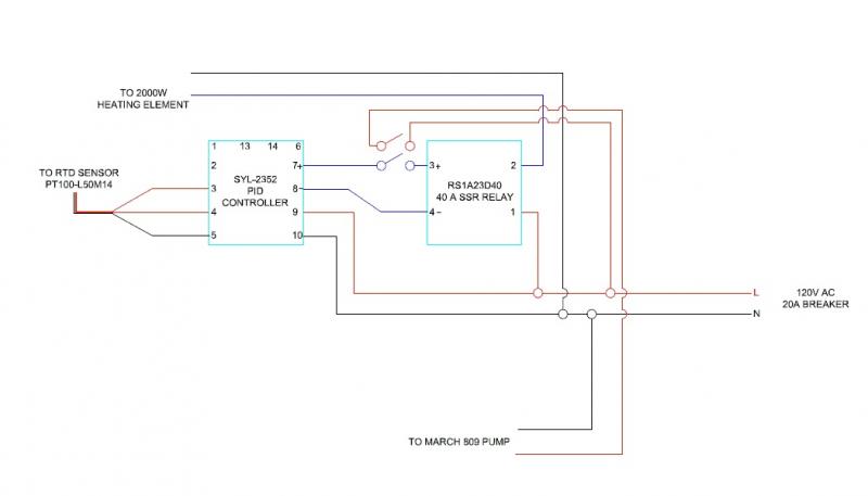
I'm guessing you meant to install the switch between them. If so, here is the updated electrical diagram. What do you think?

RIMS Electrical Diagram-First Revised.jpg
 
Also, if I'm going to include room for larger future capacity, how many amps should I prepare for? 25A allows me to use 10 gauge wire, while 40 amps will require 8 gauge wire. This will also affect the size (and consequently the price) of the dpst switch.
 
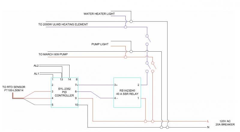
Ok, so I thought about it more last night, and I thought that the dpst switch would probably have to be between the relay and element, not the relay and the PID. I also cleaned up the layout to be closer to how it will be installed.

RIMS Electrical Diagram-Second Revised.jpg
 
I'm guessing you meant to install the switch between them. If so, here is the updated electrical diagram. What do you think?


You almost have it. The switch you put in will make sure the pump is running when the PID is calling for heat. That's good. But what if you only want to run your pump, such as when you are pumping through a chiller or pumping into your primaries? You could control the element through the PID by reducing the set value to be low enough that it doesn't fire, or you could install a second switch that controls just the element. Place this one after the Pump/SSR switch and you'll be able to independently control the element without having to adjust the PID.

You want independent control of the pump and element anyway - this prevents the element from firing if the pump isn't on.

Does this make sense?

In the picture below, the switch on the left controls the pump and the switch on the right control the element. What you don't see is the interconnect wiring between the two. I wanted to have the PID operate independent of the Pump and Element. That way I could use it as a temperature monitor.
DSC07368.jpg


This is my schematic. The pump switch has the capacity to handle both the pump and element power. It has to be on in order for power to flow to the element switch. Then the element switch has to be on in order for the power to flow to the element. I suggested and you implemented the SSR control line instead of the element power line. I think that solution is better since the SSR cannot fire if it cannot get a signal - and you have the switch to the element in case the SSR fails closed - which is usually the case when they fail.
MyControllerSchematic12-16-10-2.jpg


You are headed in the right direction. Keep up the good work and keep us informed of how it's going. Keep asking questions too.

Paul
 
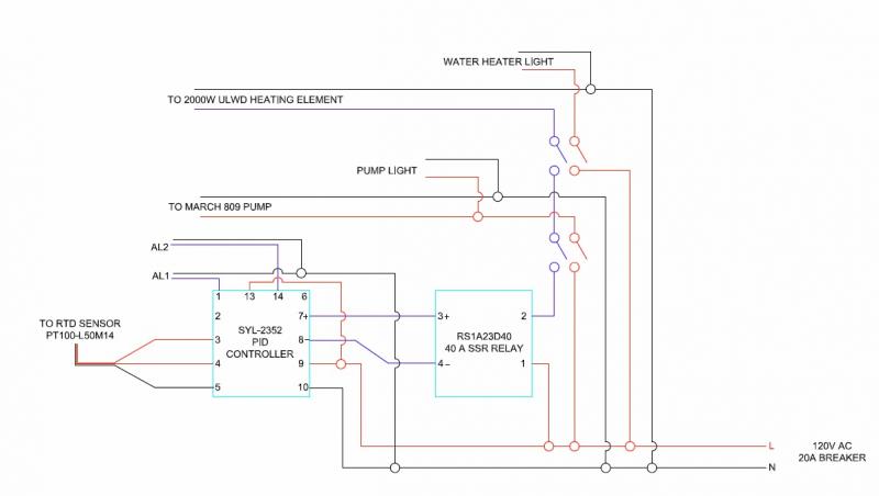
I'm with you now. Where did you purchase your switches and lights? I like how you set them up so you can easily see when they are on and off. I'm also a pretty big fan of the ammo box to contain everything. I've already bought one on ebay. Another question, do you know much about the alarm outputs on the PID? Going by the alarm outputs below, is there a way to set the alarm so that AL1 will power if the temperature is not met, and AL2 will power when the temperature is met? Do these alarms need relays as well? I think it would be pretty sweet if I could get that to work.

RIMS Electrical Diagram-Third Revised.jpg
 
I'm with you now. Where did you purchase your switches and lights? I like how you set them up so you can easily see when they are on and off. I'm also a pretty big fan of the ammo box to contain everything. I've already bought one on ebay. Another question, do you know much about the alarm outputs on the PID? Going by the alarm outputs below, is there a way to set the alarm so that AL1 will power if the temperature is not met, and AL2 will power when the temperature is met? Do these alarms need relays as well? I think it would be pretty sweet if I could get that to work.

The lights are 120v and I got them from the local electronics surplus store.

I'm confused by what you are asking about for the alarms. What are you trying to accomplish here? Do you want an alarm to sound every time the element kicks in? I only use the alarms in conjunction with a timer. Go to the Auber web site and look up the SYL-2352 PID. Down the PDF of their manual. It shows how the alarm works. If you're simply looking for a way to light up a pilot light when the element fires, that's easy enough to do and does not require alarms.

The way mine are configured is when the pump switch is turned on, the yellow pump pilot light is lit and the power flows to the element switch. When the element switch is turned on then the red element pilot light will light when the PID calls for heat. I.e. - it runs off the SSR.
 
Ok, heres what I had in mind. When I turn on the switch to the pump, pump light goes on. This should work with the current setup. When I turn the element on (whether the PID is calling for heat or not) the element light comes on to show it's available. This is slightly off since it's not going to turn on until the PID also calls for heat. The next two lights would be controlled by the alarm functions. One if the mash requires heating (AL1) and another if the mash is of sufficient temperature (AL2). These just basically show where the mash is in terms of being above or below the setpoint.
 
Agreed your current light setup will work for your pump and your element light will light when the element switch is on AND the SSR is closed (i.e. calling for heat). But the SSR is only going to be calling for heat if it's required. i.e. the temperature has fallen out of the hysteresis band. In this case the PID will close the relay, the element will heat up and the light will come on. The element pilot light will turn off and on per the element coming on. I think that serves the purpose of what you are asking AL1 and AL2 to do.

I personally do not use either AL1 or AL2 and I've not bothered to learn how to wire them up. However, if you have read the manual for the PID, that should give you the information you need. If not, then there are others here who have wired the control panels with alarms.

P-J, Kladue, Earthbound, Kosmokramer, etc? feel free to jump in here.
 
Ok, slight modification. Now, when the element is AVAILABLE, not just on, the light will turn on. Kind of like all systems ready. I think I'm going to see what Aubers has to say about setting up their alarms to do what I want to do (again, set light/alarm 1 to go off when heating is required, light/alarm 2 to go off when heating has been met)

RIMS Electrical Diagram-Fourth Revised.jpg
 
Ok, I think I got it now. According to the instruction manual, I think this is how the alarm needs to be wired. If you set the controller value C=1, then AL1 is activated when Deviation high alarm occurs. Set D=0, and then AL2 is activated when Deviation low alarm occurs. Deviation from the temperature setpoint is controlled by the functions SV+(Hy-1)-Hy for deviation high and SV-(Hy-2) +Hy for deviation low. Therefore, set Hy-1 and Hy-2 =0 and the alarm will go off whenever the temperature is outside of the hysteresis band (Hy). The initial setting for Hy is 0.3. What this all ends up meaning is that if I am trying to control the mash by setting the set value (SV) to 155, and the temperature is above 155.3, the deviation high alarm goes off, and vice versa, if the temperature is below 154.7 the deviation low alarm goes off. With the following wire diagram and the setpoints I've just explained, I will have a light go on when I turn the pump on and when the water heater becomes available (I flip the switch, but the controller doesn't necessarily have to be calling for heating). Now when it does require heating, the deviation low light goes on and the heater is turned on. When it reaches temperature, the deviation low light turns off and the deviation high now turns on. That's exactly what I was looking for, so unless I've made any mistakes, the following diagram should be my final one that I'm going to go with.

EDIT: These values are part of a formula for the AL-P parameter. The formula is: AL-P=Ax1 + Bx2 + Cx4 + Dx8 + Ex16 (For my system, I ended up going with 0x1 + 0x2 + 0x4 + 1x8 + 1x16 = 24)

RIMS Electrical Diagram-Fifth Revised.jpg
 
I don't know if you factored this in or not, a 2000 watt element at 120v is 1200/120=16.7 amps and adding your pumps onto that bumps it up at least another amp of two. A 20amp circuit breaker is only meant to take a continuous load of 80% or 16 amps. You probably won't trip the breaker if nothing else is on that circuit. Being as that you are in the design stages it may not be a bad time to address this before you have a problem later. If you do plan to go this route with the 120volt system consider changing the outlet out where you plan on plugging your panel in to a 20amp rated one. Most outlets in a residence are only 15amp rated even though they may be on a 20a circuity. The code allows this as basically no residential loads are that high on a single plug. You'll likely met the outlet if you put that much load on it for sustained amount of time.
grandequeso
 
Well, I decided I was going to go with all copper plumbing, and the closest to a 2000W heater I could find with a low watt density was a 1700W LWD heater. So using that, 1700/120=14.2A. Add in the pump, and I'm right at 16A. I think I should be safe where I'm at, but if I decide to upgrade in the future, this will be something I'll address then. I will make sure that outlet is rated for 20 A. Great point about the outlet though! It's a cased outdoor porch outlet, so I feel like it's one that they wouldn't be able to cheap out on as easily, but you do never know.
 
Sounds good in that case. consider using a 20a rated male cord cap as well. looking foward to how your build goes.
Grandequeso
 
Also make sure the breaker and wiring servicing the outlet you plan to use is rated for 20 amps.

You have a good plan!
Paul
 
Yea, I'm excited to get started. I'll try to document a lot of the build in case it works out well and others wish to follow. Thanks for all the feedback Paul, I really appreciate it!
 
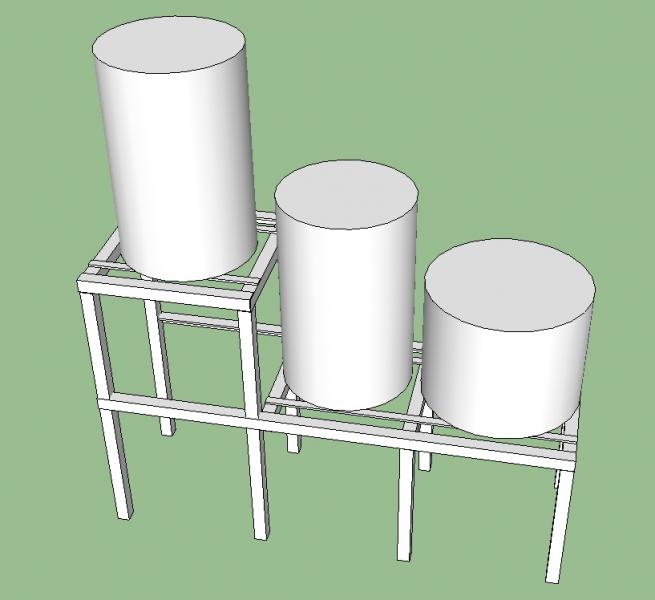
Ok, so I've ordered everything that I'm going to need for this build and I'm waiting on the last 25% of the pieces to come in the mail. I just finished laying out the structure and I'm going to find an aluminum supply store. I'm attaching the model I built with sketchup so I could resolve issues I may have in design. Let me know what you guys think. Heres the parts list for the structure:
(Q) Desc-W"xT"xL"

(2) flat aluminum bars -1"x1/4"x19.5"
(2) flat aluminum bars -1"x1/4"x36"

(9) square tubes - 1.5"x1/4"x18"
(4) square tubes - 1.5"x1/4"x36"

(2) angled aluminum - 1.5"x1/4"x19.5"
(2) angled aluminum - 1.5"x1/4"x55.5"

I did a calculation to figure out the total weight of the structure to see how manageable this is going to be unloaded and my calculation came up with just over 51 lbs (using a density of 0.10 lbs/in3). This seems pretty manageable to me.

RIMS Frame.jpg
 
Quick question, could one use a duplex receptacle and control each outlet separately or do you need to have two different outlets?
 
Quick question, could one use a duplex receptacle and control each outlet separately or do you need to have two different outlets?
What do you mean exactly? Are you looking to have the ability to switch on/off each receptacle in the outlet?
The way I plan to wire my system, I will have everything hooked up with a single plug to a single receptacle. If you are planning on having two plugs, you're total amperage on the whole outlet is limited by the both the outlet rating and the breaker serving that outlet.
 
I really dont know what I mean, I plan on plugging the control panel in the wall on a single socket to power the control panel (4352 auber and 25A SSR) to control a 1500w extra low density coil, and thought of also having a switch to power on my chugger pump. very similar to your setup. so i would have an on off switch for the element and an on off switch for the pump, does that make sense? Also what gauge wire do people use? Would 20 gauge work?
 
Back
Top