Electric newb - venturing into a 30a HERMS

Homebrew Talk - Beer, Wine, Mead, & Cider Brewing Discussion Forum

Help Support Homebrew Talk - Beer, Wine, Mead, & Cider Brewing Discussion Forum:

This site may earn a commission from merchant affiliate links, including eBay, Amazon, and others.

Dustin_J

Well-Known Member
Joined
Mar 16, 2006
Messages
273
Reaction score
103
Location
St. Louis, MO
So, the wife and I just moved into a new house (1904 construction, stone foundation), and I am interested in moving the brewing activities indoors into our basement. I currently have a single-tier converted-keg propane-fired stand, a single March 809 pump (I'm a batch sparger), and whirlpool immersion chiller as the basics of the system.

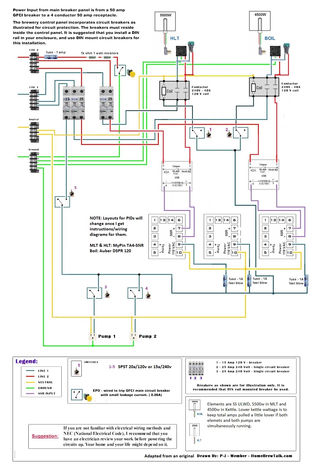
I'd like to go electric, and I'm strongly considering a simple 30a (EDIT: will be doing 50a) HERMS System. The idea would be that I would just convert the existing stand/system by adding elements, a simple control panel, a herms coil in the MLT (I already have plenty of 1/2 copper from a previous chiller bulid), and 1 additional pump.

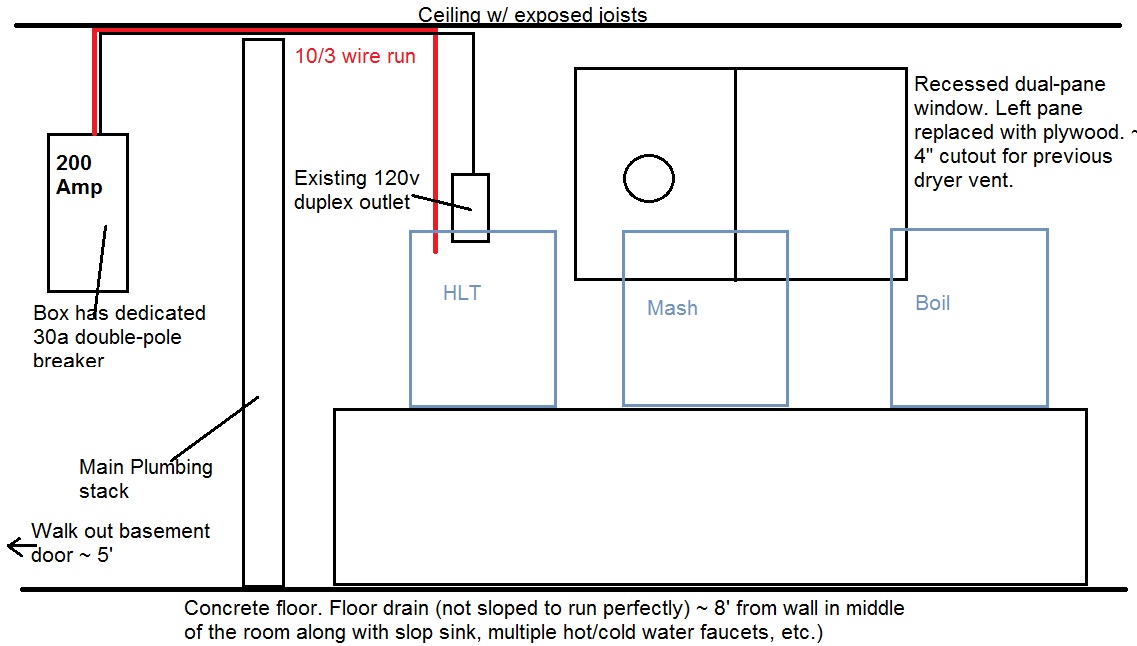
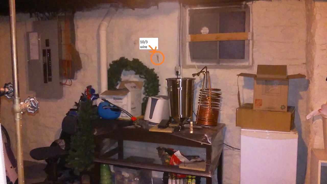
I've attached a diagram of the space (I'll post some pictures later) I'm considering, and a few initial thoughts. Any input/help folks could provide as I move forward with this would be greatly appreciated.

For background, even though I'm using kegs, I'm almost exclusively interested in 5 gal batches and batch sparging.

Rough Illustration
SsCLnlA.jpg


Stand Area
rqQmytK.jpg


Cleanup/water/drain area
LR2JSqO.jpg


The basics:
- Electrical: The main electrical box (200 amp service) for the house is nearby. There is an existing, dedicated 30a double-pole breaker in the box with a 10/3 wire run (see diagram), but no plug is installed. Also, no GFCI right now, but I think I'd probably just have a 30a GFCI breaker installed in the box. Also, a 120v outlet on a separate circuit is already wired (but could easily be moved a bit) in the space. (EDIT: will be running 6/4 from the panel with a 50a GFCI breaker.)

- Ventilation: A dryer was apparently installed here at one time. There is an existing 2-pane window (recessed ~ 6 inches), which 1 pane has been changed to plywood with a ~4" hole in place for the dryer vent. This could easily be changed to provide a larger outlet directly outside. Also, the walk-out door for the basement is ~ 5 feet away, which would be easy to crack open to provide replacement air as needed.

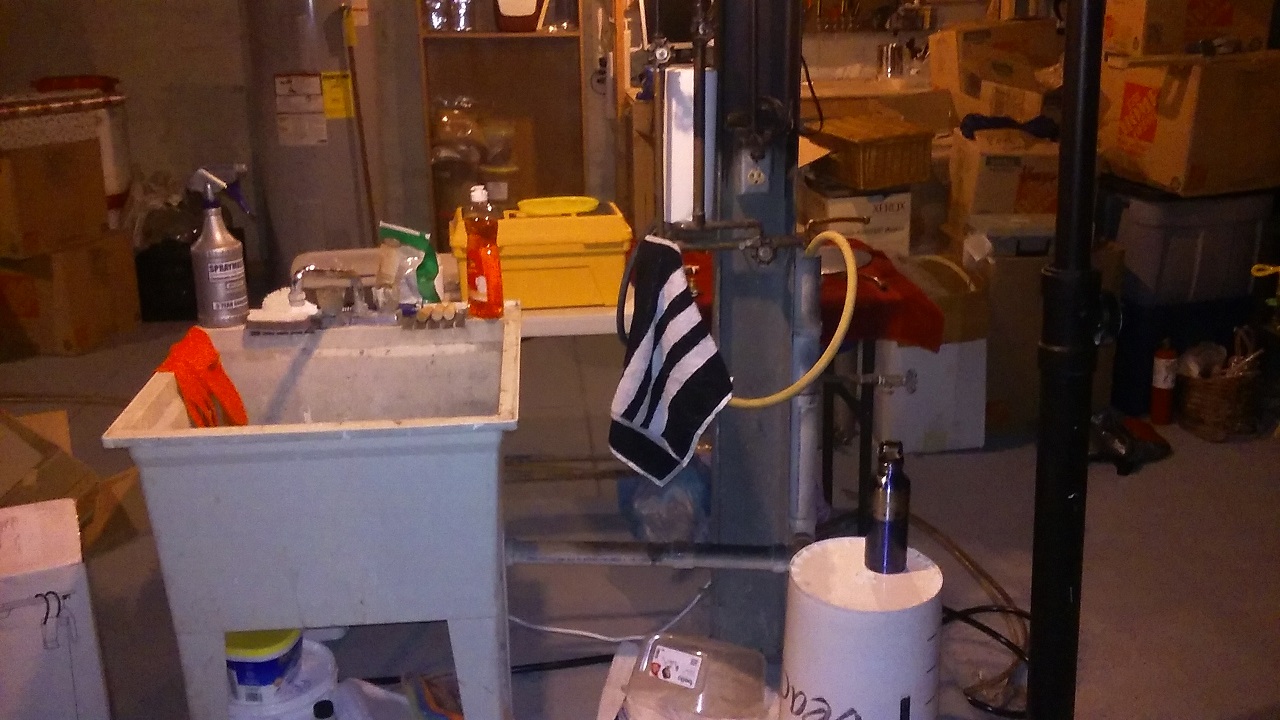
- Water/drainage: If you put your back against the wall in the diagram, about 8 feet away (in the middle of the room) is where the washer(s) was previously installed. There is currently a slop sink, multiple operating (and free) hot & cold water faucets, and a floor drain. The slope of the concrete floor doesn't allow for easy drainage (i.e. I can't just slop water everyone and expect it to find the drain), but it is close enough that hoses could easily be ran to it for drainage if I'm careful.

After doing a little research, this seems like a pretty ideal setup other than the lack of really clean drainage. Does anybody see anything glaring that I'm missing here?
 
Last edited:
Don't think about that gfci, do. You must be safe brother. Otherwise I think your plans sound solid. I'd do 240v service with 5500w elements for a faster brew day and to allow for expansion if you move up to 10g.
 
Don't think about that gfci, do. You must be safe brother. Otherwise I think your plans sound solid. I'd do 240v service with 5500w elements for a faster brew day and to allow for expansion if you move up to 10g.

Of course! The "thinking" part was basically 30a breaker vs Spa panel - there will definitely be GFCI. I can't imagine it'd be good to die from electric shock. :mug:
 
If you're in the basement, close to the panel, I'd consider upgrading the feed to 4-wire. Unless you plan to use a separate 120V circuit for pumps. It's much neater IMO too have all the controls in one box on one circuit...
 
If you're in the basement, close to the panel, I'd consider upgrading the feed to 4-wire. Unless you plan to use a separate 120V circuit for pumps. It's much neater IMO too have all the controls in one box on one circuit...

Good idea! It's probably only 12-15' of wire and would definitely make things tidier.
 
When I started my basement brewery it was a cinder block room. I ran 10/3 to my control panel and then to both of my elements. It’s nice to have water supply/drain for sure. Check out the photos in my signature.
 
Since your are not too far from your panel, why not go with 50 amp service?

The cost between the two is really only the wire (6ga vs. 10ga). That will be very little for you. A 50 amp GFCI breaker can be had pretty cheap by buying a spa panel kit and just installing the breaker that comes with it in your main panel (they do have to be the same type of breaker -Homeline, QO, etc). You will also save a little by not needing switching contactors since you can run two elements at once - electrical design will be simpler.

I currently have 30 amp but will upgrade to 50 once my new brew room is done. 30 amp becomes limiting as your system grows...

Hmm, given that I was planning on switching to 4 wire anyway, that'd mean running new wire regardless. Also, 50 amp would allow for heating strike water and HLT water simultaneously, which I didn't really consider until searching a bit more. You've convinced me - 50a it is.
 
Since your are not too far from your panel, why not go with 50 amp service?

The cost between the two is really only the wire (6ga vs. 10ga). That will be very little for you. A 50 amp GFCI breaker can be had pretty cheap by buying a spa panel kit and just installing the breaker that comes with it in your main panel (they do have to be the same type of breaker -Homeline, QO, etc). You will also save a little by not needing switching contactors since you can run two elements at once - electrical design will be simpler.

I currently have 30 amp but will upgrade to 50 once my new brew room is done. 30 amp becomes limiting as your system grows...

The panel designs for simultaneous element use vs. one element at a time, will both have two element power enable contactors. The difference is that for the simultaneous use panel, each contactor will have it's own controlling switch, whereas the one element at a time panel will use a single three position switch to select between the contactors. The 50A panel will also need two 30A 2-pole breakers (or four 30A fuses) if you want to run 10AWG wire for the element power cords instead of 6AWG. So, the 50A panel is a little more complex than the 30A panel. But, you should base your decision on how you want to use your system. If you are going to the trouble and expense, make sure you'll be happy with the result.

Brew on :mug:

Either way I decide to handle the GFCI (spa panel or breaker itself), I think I'll just run the 6/4 wire since it's only about 15' of wire needed and it can be run directly through the floor joists - very straightforward. It needs to be rewired anyway, so I might as well go big as everyone suggests. Regarding GFCI, I have a GE panel, and it looks like I can get a GE 50 amp GFCI breaker for < $100. I definitely need to think through this all more, but running 6/4 wire from the GFCI breaker directly in the panel would be really easy and would eliminate the need for the spa panel, without much additional expense.
 
Either way I decide to handle the GFCI (spa panel or breaker itself), I think I'll just run the 6/4 wire since it's only about 15' of wire needed and it can be run directly through the floor joists - very straightforward. It needs to be rewired anyway, so I might as well go big as everyone suggests. Regarding GFCI, I have a GE panel, and it looks like I can get a GE 50 amp GFCI breaker for < $100. I definitely need to think through this all more, but running 6/4 wire from the GFCI breaker directly in the panel would be really easy and would eliminate the need for the spa panel, without much additional expense.

I agree that you might as well run a 50A service as long as you are rewiring. But, I think you're going to want to put an outlet between your breaker panel and control panel. I believe if you hardwire the control panel to the breaker panel, then the control panel becomes part of the structure wiring, so has to be code compliant, and maybe require an inspection.

My previous comments were more about what's inside the control panel than the power to the control panel.

Brew on :mug:

Thanks Doug - I should have been more clear. Yup, the 6/4 would run to an outlet, then the control panel would plug into the that. 2 separate entities, so to speak.

With that being said, I appreciate the clarification regarding the control panel. I had a few basic 30a panel builds to work off, but of course things are going to change now, and it sure would be a drag to wire things incorrectly so that only 1 element could be fired at a time.
 
The panel designs for simultaneous element use vs. one element at a time, will both have two element power enable contactors. The difference is that for the simultaneous use panel, each contactor will have it's own controlling switch, whereas the one element at a time panel will use a single three position switch to select between the contactors. The 50A panel will also need two 30A 2-pole breakers (or four 30A fuses) if you want to run 10AWG wire for the element power cords instead of 6AWG. So, the 50A panel is a little more complex than the 30A panel. But, you should base your decision on how you want to use your system. If you are going to the trouble and expense, make sure you'll be happy with the result.

Brew on :mug:

That depends on how you set things up; I think you'd still be ok with one large contactor tied to a single switch to kill power to all heaters at once. Something like this is fairly inexpensive: https://www.amazon.com/Baomain-Contactor-Universal-Circuit-Control/dp/B01J1RFZSY/ref=sr_1_1?ie=UTF8&qid=1508270598&sr=8-1&keywords=baomain+contactor I'm not sure why you would have to have a contactor for each heater if you have a master one for everything.

I do agree that 2 2-pole breakers are needed, depending on wire sizes and plugs used for each heater, but those are usually only around $10-15: https://ebrewsupply.com/collections/din-rail-hardware/products/32a-double-pole-breaker-new-version
 
Last edited by a moderator:
That depends on how you set things up; I think you'd still be ok with one large contactor tied to a single switch to kill power to all heaters at once. Something like this is fairly inexpensive: https://www.amazon.com/Baomain-Contactor-Universal-Circuit-Control/dp/B01J1RFZSY/ref=sr_1_1?ie=UTF8&qid=1508270598&sr=8-1&keywords=baomain+contactor I'm not sure why you would have to have a contactor for each heater if you have a master one for everything.

...

I suppose you could use a single contactor to do power enable for both elements, but I would never design a panel that way. If one of your SSR's fails (they tend to fail in the "on" state) then you have no way to kill power to only the affected element.

Brew on :mug:
 
Last edited by a moderator:
Either way I decide to handle the GFCI (spa panel or breaker itself), I think I'll just run the 6/4 wire since it's only about 15' of wire needed and it can be run directly through the floor joists - very straightforward. It needs to be rewired anyway, so I might as well go big as everyone suggests. Regarding GFCI, I have a GE panel, and it looks like I can get a GE 50 amp GFCI breaker for < $100. I definitely need to think through this all more, but running 6/4 wire from the GFCI breaker directly in the panel would be really easy and would eliminate the need for the spa panel, without much additional expense.

A lot of times, it's actually cheaper to buy a spa panel with a breaker that matches your main panel (don't ask me why, no idea on that!). Just take that breaker and install into your main panel and throw away the rest of the spa panel. Something like this should work for you: http://www.homedepot.com/p/Midwest-Electric-Products-50-Amp-240-Volt-240-Watt-Non-Fuse-Metallic-Spa-Panel-Disconnect-with-GFI-UG412RMW250P/100686230

30 amp GFCI breakers are harder to find (not impossible, usually special order) whereas 50 amp spa panels are usually in stock at most big box stores. I don't think installing a spa panel makes sense most of the time; only if you need something portable or can't make permanent changes due to renting does it make any sense IMHO.
 
I suppose you could use a single contactor to do power enable for both elements, but I would never design a panel that way. If one of your SSR's fails (they tend to fail in the "on" state) then you have no way to kill power to only the affected element.

Brew on :mug:

I think that's overkill (nothing wrong with overkill :mug:). If the purpose of the kill switch is to give you the ability to disconnect power due to a failed SSR, then there really isn't much difference between one or both heaters going out in that situation. In either case, your brew day is messed up. Recovery will require troubleshooting inside your panel either way, and if you have to rewire a heater to the other SSR, then you can remove the bad SSR and still finish your brew day with only one heater.

In any event, you are safe, since you have a way to remove power to your heaters. Two contactors vs. one is more about recovery in the event of a failure, which should be low assuming you sourced quality components. It depends on your tolerance for spending money on the devices and wiring compared to the actual risk of a component failure.

Some things are no-brainers (like a GFCI breaker); others are debatable depending on how you want to run your system. Debate is good; gives the OP options to consider and they can decide what's most important to them.
 
Hi everyone,

I've been putting some thought/research into things. I'd sincerely appreciate some thoughts on components and, potentially, some help with components and wiring.

Functionally, the plan is 50 amp service, 2 SS ULWD ripple elements (1 5500w in HLT, 1 4500w in Boil kettle). 2 pumps (1 March 809, 1 Keg King mkii), MyPin TA4-SNRs for the HLT (controlled) and mash (temp monitoring only), an Auber DSPR120 for the boil, and 3x RTD PT100s (with XLR connections) for temp sensors.

I just picked up a used Hoffman 12"x14"x8" enclosure (with backplate) for a nice price on Ebay, so there should be plenty of room. I'd like to be able to run both elements and pumps simultaneously if necessary for doing back to back batches or, potentially, heating (and recirculating) my strike water in the boil kettle at the same time that I'm heating (and recirculating) the water in the HLT. The 4500w in the boil is so that I can keep the total amperage used a little lower in this case. I can't image that being much of an issue with 5-10 gal batches, which is as large as I'll be able to handle with keggles and as large as I'll ever want to go.

Regarding the panel, I just want to be able to turn the elements & pumps on/off independently, have indicator lights that show when the elements are actually firing, have an un-keyed master power switch, and have an emergency stop. I'm not too concerned with timers, alarms, etc. directly on the panel as I'll just use my phone or computer that are close by and easier to deal with. As you can see, I haven't settled on switches for the master on/off and the element on/offs. Of course, the components/values may change moving forward

Please see below for a crack at the panel layout.

Thank you!

Control panel layout v1.jpg
 
Do you want any interlocking to prevent you from turning on the main power if a pump switch or element enable switch is on? If so, the pump and element switches need to have two sets of contacts, 1-NO and 1-NC. It also requires the addition of a main power contactor if you aren't already planning on one.

Brew on :mug:

To be honest, I hadn't really thought about it. If it doesn't add a ton of complexity/cost, it sounds like a good idea from a safety standpoint.

I still have plenty of work (and probably a lot of questions) regarding how to actually wire things. Not my forte, but I have some diagrams to go off of for now. Thanks Doug, you've already been a big help both here and in all of the other threads I've been browsing through.
 
Here's the first crack at a wiring diagram - I strongly welcome any input or assistance any of you might have. As you can see, this was adapted and cobbled together from a few different P-J diagrams.

A few quick things. The PIDs are not correct, but I'll update them once I purchase them and get wiring diagrams/ instructions for them. Also, this isn't intended to have the safe start/interlocking. After thinking about it, I don't really think it's necessary.

I have some questions about switch #5 ("main power") in particular. I couldn't find a specific diagram that had a switch in the position that it is in. The intent is that it influences everything in the 15amp/120v portion by directly turning on the the PIDs and allowing me to turn the pumps and elements (via the contactors) on or off independently once it's on. Also, it was intended that this wouldn't allow the elements to be "armed" unless both the main power switch (#5) and the specific switch for the element are both on. Does this wiring appear to achieve that?

DiagramV1
u0dVg36.jpg
 
...

I have some questions about switch #5 ("main power") in particular. I couldn't find a specific diagram that had a switch in the position that it is in. The intent is that it influences everything in the 15amp/120v portion by directly turning on the the PIDs and allowing me to turn the pumps and elements (via the contactors) on or off independently once it's on. Also, it was intended that this wouldn't allow the elements to be "armed" unless both the main power switch (#5) and the specific switch for the element are both on. Does this wiring appear to achieve that?

...

Yes. I've done designs that basically work the same way.

Brew on :mug:
 
Since your are not too far from your panel, why not go with 50 amp service?

The cost between the two is really only the wire (6ga vs. 10ga). That will be very little for you. A 50 amp GFCI breaker can be had pretty cheap by buying a spa panel kit and just installing the breaker that comes with it in your main panel (they do have to be the same type of breaker -Homeline, QO, etc). You will also save a little by not needing switching contactors since you can run two elements at once - electrical design will be simpler.

I currently have 30 amp but will upgrade to 50 once my new brew room is done. 30 amp becomes limiting as your system grows...
While I agree with this also make sure your house can handle it.. mines only a few years older (late 1800s) and I only have a 100a main service... as it stands now my 30A panel works but I can tell 50a would likely be too much at times by the dimming of all my ceiling lights in the house. (I also have other large electric appliances)
 
While I agree with this also make sure your house can handle it.. mines only a few years older (late 1800s) and I only have a 100a main service... as it stands now my 30A panel works but I can tell 50a would likely be too much at times by the dimming of all my ceiling lights in the house. (I also have other large electric appliances)

You should really have your electrical service looked at it you have dimming lights when you run your brewery. I would suspect some loose connections on your entrance conductors. Your brewery is on a separate circuit from your lighting. The only thing they should have in common is from the breaker panel back to the point of service entrance. A bad connection there would cause dimming lights.

At times, my brewery elements can draw over 60A on my 100A service. I have never had any dim lights while running it.
No its not a bad connection been through it a few times already. All the lights in my house do it slightly as the element pulses... Its the fact that I only have a 100a main service and a 50a hot tub 150gallon reef tank as well as 1500ft of house on the service with multiple ac units and fridges/kegerators. I have had an electrician friend brew with me a couple times and he concurred its normal when something draws off the line..(im aware they are only connected at the main panel). When I say dim I mean slightly not enough where anything else is effected. I see the same thing at many customers at work when the heating elements in the machines I work on kick on in some office enviroments

My panel is unusual with a 60a "light main" breaker and the 240v breakers bypassing the main in its design. The aluminum clad wiring isnt helping either. the wire coming in appears to be 4 or 2 gauge so I may be assuming thats 100amps? Its also what the electrician that inspected my hot tub wiring told me I have.. Its a church/schoolhouse -duplex conversion so I have two services like this actually.

Glad to hear you've checked into it. You must be drawing enough at times that you are getting some voltage drop on your service conductors.

Have you had your utility company look it over? They may have bad connections or undersized conductors from the transformer. If you have a smart meter, you should be able to get a load survey and see what your actual peaks are.
 
While I agree with this also make sure your house can handle it.. mines only a few years older (late 1800s) and I only have a 100a main service... as it stands now my 30A panel works but I can tell 50a would likely be too much at times by the dimming of all my ceiling lights in the house. (I also have other large electric appliances)

Good point. We have 200 amp main service, recently gone through just before we purchased the house. Should be good to go.
 
Glad to hear you've checked into it. You must be drawing enough at times that you are getting some voltage drop on your service conductors.

Have you had your utility company look it over? They may have bad connections or undersized conductors from the transformer. If you have a smart meter, you should be able to get a load survey and see what your actual peaks are.
I havent had any utility company look at it.. again I see it all the time in the office building I work in when some of the smaller machines I work on kick on if they are on the same circuit. my brewery may not be on the same circuit its still a sizable draw when other things are already using power. I do have an infra red heat gun and have used it to check breaker temps as I was concerned about having the hot tub kick on at the same time as im brewing when I installed the brewery.. there was nothing usual.
So im the only one that ever noticed a slight momentray change of the intensity of the lights when a large appliance kicks on?

I do know all my first floor wiring and some of my second floor wiring is done with 12awg and 20 amp breakers and one second floor circuit has all the ceiling lights and a couple wall plugs on it which is the one where I notice it the most likely due to being on the same old circuit.
 
So im the only one that ever noticed a slight momentray change of the intensity of the lights when a large appliance kicks on?

the only time i really notice it is when i am in my electric sauna. it is a detached structure about 150' or so from my house. there is a 40w incandescent lamp in the hot room on a dimmer and with that turned all the way down, i can see it pulsating if the washing machine happens to be running at the same time (annoying). can't say i notice other lights in the house flicker if the air conditioner turns on, etc. but i also have a 200 amp service.

with only a 100 amp service, you are bound to have at least some voltage sag issues, however minor...
 
Quick Update - Things are progressing. In Order:
- Made a few small edits to the wiring diagram
- Got the stand and kettles in place and did a little preliminary plumbing, including getting the element installed with HotPods (not pictured).
- Installed a 50a 240v outlet with a 50a GFCI breaker in the main panel
- Got some of the internals together in anticipation of wiring
- Got some bling
- Last but not least, got the control panel laid out and painted. You can't see it in the crappy picture, but the silver is sparkly/metal flake and the blue is basically a candy, so the sparkle pops through it a bit. My old man is an auto body guy/painter, so I had to go for something. He'd probably be amused, if not exactly impressed.

The next big steps are getting the panel components installed, wired, and tested; and finishing the plumbing for the HERMS coil. I have about 25-30' of 1/2" copper from a previous chiller build that will become the HERMS coil. It'll be connected via weldless compression bulkheads from bargainfittings. As for wiring, my future involves lots of cutting, stripping, crimping, wrangling, and cussing - which sounds a lot like a cowboy party come to think of it :mug:

DiagramV2 - with notes.jpg


stand.jpg


outlet.jpg


backplate.jpg


bling.jpg


panel.jpg
 
Hi everyone,

Initial tuning/testing went fairly well, but there were a few challenges. 1 has to do with the MyPin TA4 autotune being wonky, but that should be sorted out thanks to some other posts here which suggest manually setting the P & I values and turning off D.

The slightly more annoying problem is that the GFCI tripped at one point. Just to summarize, the controller is set up for 50amps, with a 50amp GFCI breaker in the main panel, and 5500 and 4500 watt elements in the HTL and boil kettle, respectively. In terms of the process, the HLT element and 1 pump were on for about 30 minutes during some initial testing, temp probe calibration etc, and everything was fine. I then decided to fire up the boil kettle element while also running an autotune cycle on the HLT PID. After about 25 minutes of this (with both elements firing at full power multiple times from what I could tell), the GFCI tripped. There were noticeable signs of shorts anywhere. The breaker itself felt warm, but certainly not hot, to the touch. I reset the breaker and tried to see if things would cause any problems If only the boil element and the 1 pump were running. Doing this for 45 minutes didn't cause any issues. I then shut off the boil element and ran another autotune cycle with only the HLT element active - no problems there.

All of the connections in the controller itself were secure with no signs of scorching. I'm planning on double-checking everything in the elements/enclosures (Hot Pods), the stove cord/plug, the wall receptacle the controller plugs into, and the GFCI breaker in the panel. Any other thoughts on where to look and what to look for? It seems odd that something would short and trip the GFCI only when both the HLT and Boil Kettle elements are firing simultaneously but not when they are operating separately.
 
Last edited:
I think it's more likely that the overcurrent breaker tripped rather than the ground fault protection. A return current fault should not be load dependent, but it sounds like your trip was load dependent. Sounds like something is drawing more current than it should, or your breaker wants to trip at less than 50 amps.

I would suggest measuring the resistance of your heating elements. The 5500W element should have a resistance of about 10.5 ohms, and the 4500 should be about 12.8 ohms. If either is significantly less than that, then it is drawing more current than it should. Also, did you turn your pump on while both elements were powered up? A motor can draw much more than it's stated current consumption on start up.

Brew on :mug:

Thanks Doug! The pump was continuously running during all of this, so no sudden starts. I tested resistance as suggested with my (cheap) meter that reads ~.9 ohms when I touch the test leads together. The boil element (4500w) reads 13.7 ohms, and the HLT element (5500w) reads 11.4 ohms. So, with subtracting .9 from each reading, it looks like they're dead on. FWIW, all of the wiring for the breaker, the wall plug, and box looks to be in order. I guess it's the GFCI breaker, which isn't a huge surprise given that a lot of the reviews I saw for the GE 50A gfci breakers (or the spa panels they are included with) discussed low/nuisance tripping. But, my panel doesn't list alternatives, so I'll try another GE breaker.
 
For what it might be worth, Harbor Freight sells a mini sized meter that includes a clip on ammeter. Small enough to reach into a small panel and check current on individual legs. I think I paid less than $15 US.

Caution. You have to put your hand in a box with live 240 power. At your own risk. I did not say this. I was never here.
 
I'm an electrician for twenty some years now. Breakers can do weird things. When I get a call for a tripping breaker, I usually have the customer cycle the breaker on and off a few times. New breakers come in the tripped state. I never just turn them on from that state... Usually off/on/off/on a few times to make sure the internal mechanism is working and properly set. This takes a FIRM snap back and forth (no limp wristing here). I have saved a few customers a service call with this advice.

Like Doug said, I don't think you were tripping on GFCI. The breaker is weak or just not properly reset...
 
From what i'm calculating you have a potential of 10kw @ 240v which could suck in 41,6Amps. So I guess that your pumps don't use the rest of the unused load (in addition to the control system load) so i could be tripping from some temporary overload. But I can't be sure of it. Also can you show us how you wired the GFCI breaker ? Because it could trip from ground fault if the neutral is not connected properly.

As for myself, I helped my brother to assemble a similar system. Except that we decided that we did not needed both Boil / HLT elements to be running at the same time. So we used a 30A breaker in the home panel and a 50 amp GFCI breaker (Spa panel - used only for the GFCI purpose).
 
Thanks for the suggestions guys. I flipped the breaker (firmly) back and forth a half dozen times, even though it has been switched on/off a handful of times already. Figured it was worth a shot.

Regarding the wiring for the GFCI breaker, I can't get a picture right now b/c the wife and BIL are marathoning movies and wouldn't take kindly to a power outage. It's wired so that the white (neutral) pigtail from the breaker goes to the neutral bus bar. Red, black, and white/neutral all go straight into the breaker (in their respective positions) from the 6/2-8/2 50A range cord that is connected to the brewing control panel. Ground from the cord goes to the ground bus bar on the other side of the panel I've triple-checked this and things seem to be in order. FWIW, both the test button on the breaker and the "e-stop" on the panel, which is wired to send current from one of the hot lines to ground, tripped the GFCI breaker during testing.

I did a "water" brew today and everything went great, but it was more of a process test for what I'll normally do for single, 5-10 gal batches, so I didn't actually need both elements on for a long period of time. Everything worked beautifully. I'll keep poking at it, but I think it's just a finicky breaker.
 
Back
Top